
Abstract
Soft robots leverage deformable bodies to achieve different types of locomotion, improve transportability, and safely navigate cluttered environments. In this context, variable-stiffness structures provide soft robots with additional properties, such as the ability to increase forces transmitted to the environment, to lock into different body configurations, and to reduce the number of actuators required for morphological change. Tensegrity structures have been recently proposed as a biologically inspired design principle for soft robots. However, the few examples of tensegrity structures with variable stiffness displayed relatively small stiffness change (i.e., by a factor of 3) or resorted to multiple and bulky actuators. In this article, we describe a novel design approach to variable-stiffness tensegrity structures (VSTSs) that relies on the use of variable-stiffness cables (VSCs). As an example, we describe the design and implementation of a three-strut tensegrity structure with VSCs made of low melting point alloys. The resulting VSTS displays unprecedented stiffness changes by a factor of 28 in compression and 13 in bending. We show the capabilities of the proposed VSTS in three validation scenarios with different tensegrity architectures: (1) a beam with tunable load-bearing capability, (2) a structure that can self-deploy and lock its shape in both deployed and undeployed states, and (3) a joint with underactuated shape deformations.
Introduction
Soft robotics is shifting the mechanical design of intelligent machines from the solely use of rigid materials toward the use of compliant materials.1–5 Soft robots rely on deformable bodies to safely navigate cluttered and human environments. A deformable morphology can enable shape adaptation to different types of locomotion, improved transportability, and storage space. 6 However, soft bodies cannot exert strong forces onto the environment and properly sustain weight after folding or deploying because of their lack of rigidity. 6 Moreover, because of their ability to freely deform in any direction, the control of soft-bodied robots can be challenging and require multiple actuators that increase the weight and size of the system. 3 These limitations could be addressed by providing soft-bodied structures with variable stiffness elements that can reversibly transition between soft and rigid states.7,8 For example, variable stiffness could increase the forces transmitted to the environment by increasing load-bearing capabilities. 8 Moreover, variable stiffness could act globally to lock the deformable robot into different body shape configurations or locally to enable deformations only along selected directions without additional actuators.8,9
Recently, tensegrity structures 10 have been proposed as an approach to design soft robots with mechanical properties similar to those of biological systems at different scales, ranging from individual cells 11 to muscular-skeletal systems. 12 Examples of such tensegrity systems include robots with embodied intelligence,13–17 bio-inspired manipulators,18,19 soft modular robots,20,21 and soft deployable robots. 22 However, in most of these case studies, tensegrity structures are characterized by a predefined and fixed stiffness. In only a few investigations, variable stiffness is addressed by enabling the change of cable pretensioning.23–25 However, this approach generates relatively small stiffness change26,27 (by a factor of 3) or requires multiple actuators that increase weight and bulkiness of the system. 28
In this study, we propose a new approach that consists of integrating variable-stiffness material within the cables of tensegrity structures. These new cables, which we call variable-stiffness cables (VSCs), can be realized by using several types of stiffness changeable materials, such as low melting point alloys (LMPAs), shape memory polymers, shape memory alloys, wax, and others. 29 These materials offer the possibility of achieving larger stiffness change without the use of additional actuators, 8 thus resulting in lighter and less bulky systems. Moreover, the differential distribution or activation of VSCs within a tensegrity structure could enable stiffness change both at the global and local structure level.
As an example of the proposed concept, we describe the design and characterization in simulation and hardware of LMPA-based VSCs within a three-strut tensegrity structure (Fig. 1a). We then validate the novel capabilities of the proposed concept in three demonstration scenarios: (1) a beam with tunable load-bearing capability (Fig. 1b), (2) a structure that can self-deploy and lock its shape in both deployed and undeployed states (Fig. 1c), and (3) a joint with underactuated shape deformations (Fig. 1d).

The VSTS design strategy implementing VSCs and the three demonstration scenarios to validate the novel capabilities.
Methods
Variable-stiffness tensegrity structure design and model
The design strategy consists of replacing cables of a tensegrity structure with VSCs. We make use of the NASA Tensegrity Robotics Toolkit (NTRT) 27 to predict how one or more VSCs affect the tensegrity structure stiffness. NTRT is an open source software package with modules for modeling and simulating tensegrity structures and robots. The NTRT can predict the large geometric nonlinear deformations exhibited by tensegrity structures subjected to external loads by using the BulletPhysics Engine (version 2.82) mixed with linear complimentary problem solvers for rigid-body dynamics. This software has been proven to estimate the rigid-body and internal cable dynamics within 1.3% error on position. 27 The internal dynamics of the spring cable is an implementation of the Hooke's law representing a first-order linear approximation of the real response of springs and other elastic bodies. All our simulation experiments are performed in quasi-static load condition and no damping is applied in the model of the cables' dynamics.
To assess the effectiveness of the proposed strategy, we use VSCs in a three-strut tensegrity structure, which is one of the simplest three-dimensional (3D) tensegrity structures often used in literature 28 : it consists of three struts and nine cables. We modeled the structure with predefined and fixed stiffness cables as given in Figure 2a and investigated replacement of which cables with VSCs could allow controlling the structure stiffness along selected deformations. In this study, we selected compression and bending as two of the fundamental structures deformation in mechanical design.

Cable strain analyses in compression and bending load conditions.
Results
Three-strut tensegrity structure with fixed stiffness in compression and bending
In the simulated 3-strut tensegrity structure, struts were modeled as cylinders with 3 mm diameter, 80 mm length, and infinite rigidity, whereas cables were modeled as springs of 50 mm length with stiffness of 35,000 N/m, which is comparable with the stiffness of a rigid plastic cable, such as nylon. The cable stiffness was calculated as EA/L, where E is the Young's modulus of the material, A the cross-sectional area, and L is the length of the cable. The structure is attached to the ground by ball joint constrains connected to the bottom vertices and compressive and bending forces are applied to its top vertices to reveal how structural deformations affect cables strain. Because of the ball joint constrains, the three cables on the bottom face are constrained and only six cables strain are recorded (Fig. 2a, c). Compression is simulated by applying three equal loads at top vertices (Fig. 2a). Bending is simulated by pulling each vertex individually in the direction opposite to intersecting the geometric center of the structure (Fig. 2b). The loads are applied incrementally until the structure compresses up to 50% of its height (i.e., 27.5 mm) and bends up to 50% of its width (i.e., 43.3 mm). The strain of the six passive cables and the overall deformations in compression and bending of the structure are recorded (Fig. 2c).
These experiments reveal that the rigid cables on the top face experience the highest strain along the selected deformations (Fig. 2c). These results suggest that to provide the tensegrity structure with variable stiffness along the selected deformations, it could be sufficient to replace only the rigid cables on the top face with active VSCs, simplifying the realization of the hardware prototype. The resulting structure is a three-strut tensegrity structure with three active VSCs cables on the top face (Fig. 3a).

Simulation and experimental results demonstrating stiffness change of a three-strut VSTS in compression and bending.
Three-strut variable-stiffness tensegrity structure in compression and bending
We added to the three-strut tensegrity model three VSCs on the top face. The VSC stiffness is defined as SVSC = x × Sr, where Sr is the stiffness of the rigid passive cables and x is the “stiffness change ratio.” When x = 1, VSCs and rigid passive cables have same stiffness SVSC = Sr = 35,000 N/m, and when x = 0.01, SVSC = 350 N/m. We then repeated the compression and bending simulation experiment (Fig. 3a, c) for the two VSC stiffness levels and observed the resulting stiffness of the tensegrity structure, measured as the slope of the load-displacement curves in both compression and bending. To evaluate the stiffness in a linear range, we analyzed the curve in the initial 5% range of the deformation (Fig. 3b, d).
The results indicate that VSC stiffness change affects the stiffness of the entire tensegrity structure in both compression and bending. When VSCs have the same stiffness of the rigid passive cables (i.e., x = 1), the variable-stiffness tensegrity structure (VSTS) displays an overall stiffness in compression of 27,000 N/m; instead, when the VSCs stiffness is reduced 100 times (x = 0.01), the VSTS overall stiffness decreases to 490 N/m, displaying a total stiffness change of ∼55 times (Fig. 3b). Similarly, in the case of bending, the stiffness is reduced by a factor of 28 times (Fig. 3d).
Based on the simulation results, we developed a hardware implementation of the three-strut VSTS replacing top-triangle three cables with VSCs (Fig. 3a, c). We fabricated VSCs using LMPA encapsulated in a silicon tube. Stiffness change was activated by Joule effect when applying electrical current. The VSCs are equipped with dedicated connectors for mechanical assembly in VSTS and for applying electric current through them. The fabrication process is described in the Supplementary Data. The fabricated VSCs have 50 mm length and 2.5 mm diameter. Their stiffness calculated in their first 5% deformation can change from 347 to 35,700 N/m when current is applied, which corresponds to a stiffness change of ∼102 times. The VSTS struts are made of carbon rods and the rigid cables are made of 3D printed nylon with length of 50 mm and cross-section area of 1 × 0.6 mm. The dimensions of the rigid nylon cables are selected to have same length as the VSCs. Moreover, cross-section area of nylon cables was selected such that the rigid cables have approximately the same stiffness as the VSCs in the rigid state: 36,000 N/m in rigid nylon cable, and 35,700 N/m in the VSCs. Therefore, according to equation SVSC = x × Sr, when VSCs are soft (x is ∼0.01) their stiffness is reduced 102 times.
The fabricated VSTS was tested in both compression and bending (Fig. 3a, c) with a universal Instron testing machine. The prototype displayed a stiffness change of 28 times in compression and 13 times in bending (Fig. 3b, d). Measured stiffness values in the soft state were in good agreement with the simulation results (error <5%), whereas measured stiffness values in the rigid state were ∼50% lower than those estimated in simulation (Fig. 3b, d). The main reason was the limited kinematic model used in the simulation to estimate the positions of the vertices and strain of the cables. The implementation of a Hooke's law linear spring neglects the nonlinearity of the VSC stress–strain behavior and its lower stiffness at the beginning of the deformation as given in Supplementary Figure S1 in Supplementary Data. Additional reason may be the presence of defects in the VSCs manufacturing process and 3D printing of the nylon passive cables, such as nonuniformity of the cross-section area along the cable length, which reduces VSTS stiffness.
VSTS beam with tunable load-bearing capability
We designed and manufactured a proof-of-concept VSTS beam with tunable load-bearing capability. The beam design was based on a tensegrity beam with fixed stiffness previously investigated in literature: the dual-stage three-strut tensegrity structure10,28 (Fig. 4a). The cables shared by the two three-strut stages at their junction were replaced by three VSCs. The VSTS beam was characterized with a universal testing machine in both compression and bending, and the results were compared with the simulations. The change of stiffness was ∼26 times in compression and 7 times in bending. The experimental data showed a good agreement (error <5%) with the simulated one in the soft state, whereas in the case of the rigid state, the experimental values were ∼50% lower than the simulated ones (Fig. 4b, d), similar to the results discussed in the previous section.

Simulation and experimental results demonstrating stiffness change of a VSTS beam made of a dual-stage three-strut tensegrity structure with VSCs at its stages junction.
In soft state, the 20 g VSTS beam bent >100% of its width under external force (weight of a 1700 g bottle corresponding to 85 times its own weight), whereas in rigid state it was able to hold the same external load with a bending of <10% its own width (Fig. 1b).
VSTS with self-deployment and shape-locking capabilities
The VSCs can be used to lock a tensegrity structure in different shapes. As an example, when a three-strut VSTS (Fig. 5a) becomes soft by joule heating, it can be compressed to a flat configuration (Fig. 5b) and hold its shape after cooling to room temperature (Fig. 5c). Because the extended VSC cable stores strain energy in the stretched silicon tube, when heated again the tensegrity structure can recover to its original shape (Fig. 5d) and lock in the originally deployed shape after cooling (Fig. 5a).
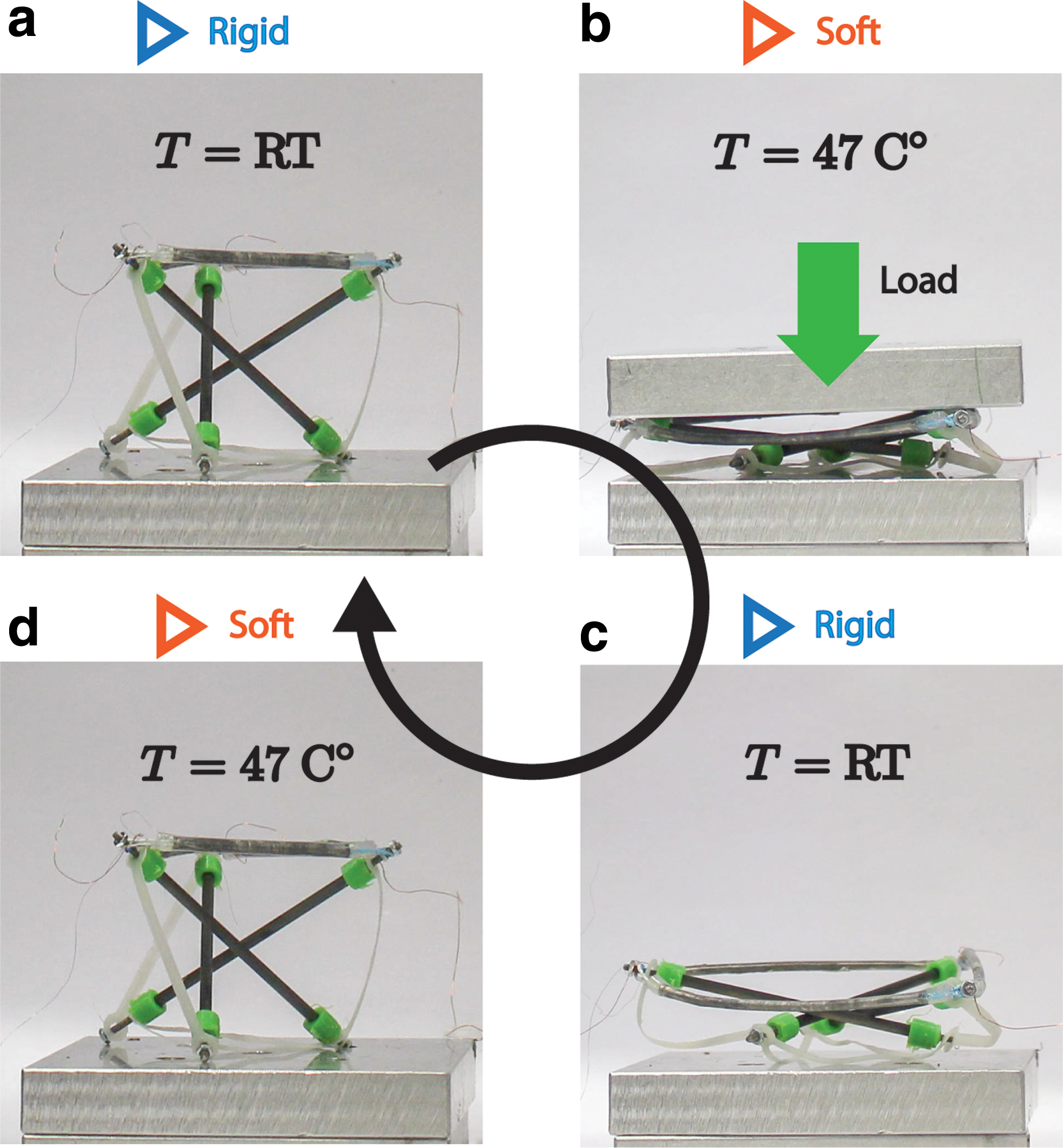
A three-strut VSTS with ability to self-deploy and lock its shape in both deployed and undeployed states.
The VSTS shown in Figure 5 weighed 12 g and in the soft state required 10 N of external load to achieve a compression of 70% of its height (Fig. 5b), which corresponded to a volume reduction of ∼90%. In deployed state, it could withstand up to 80 N with only 5% compression. The transition time from rigid to soft was ∼2.5 min by applying 1.5 A at 12 V to heat the VSC at 47°C. Transition time from soft to rigid was ∼4 min at room temperature. In a first approximation, considering a constant spring coefficient, the strain energy stored in the stretched silicon tubes during compression can be estimated using the elastic potential energy equation of a spring
VSTS joint with underactuated shape deformations
The integration of individually controlled VSCs in a tensegrity structure could enable diverse shape deformations. A differential distribution of the same actuation force throughout the tensegrity structure can be obtained by selectively controlling the stiffness of a subset of VSCs. The advantage of this approach to differential deformation of the structure is that it does not require the use of actuators for each deformation direction, which could increase the size and weight of the tensegrity structure.
As a proof of concept, we developed an underactuated VSTS joint capable of deforming in four different directions using only one actuator. The dual-stage VSTS joint was composed of two connected three-strut tensegrity structures with three shared VSCs at the junction (Fig. 6a). The two rigid surfaces of the structure, one at the top and the other at the bottom, could be connected to other components, such as robot bodies or end effectors. The VSTS joint was actuated by means of a tendon-driven mechanism placed at the base that uniformly pulled all the top surface vertices toward the base (Fig. 6a). The four different modes of actuation were achieved by simultaneously changing stiffness of the three VSCs (Fig. 6a) or by selectively changing the stiffness of only one VSC at a time (Fig. 6d).

Underactuated VSTS joint and its shape deformations.
Experiments were performed by actuating the motor at low speed (5°/s) until it reached maximum torque (7.25 N·cm) while the position of the geometrical center of the top surface was tracked by means of a motion capture system. When the three VSCs were simultaneously softened, the structure could compress up to 40% its height at the maximum torque (Fig. 6b). Instead, when only one of the three VSCs was softened, the structure could bend of ∼40° in three different directions (Fig. 6b–e, top view).
Conclusion
The VSTS described in this article offer tunable load-bearing properties, shape locking, and controllable deformations in underactuated structures without significantly affecting the size and weight of the structure. Although the cables described in this article were based on LMPAs encapsulated in stretchable tubes, other variable-stiffness technologies could be used according to the force, speed, and the magnitude or transition time. Moreover, given the scalability of tensegrity structures, 10 the proposed VSTS strategy could be applied at different scales. For example, large VSTSs could serve as a scaffold for lightweight and self-deployable bridges, infrastructures, manipulators, antennas, and buildings with the ability to lock into their deployed and undeployed configurations. 29 Human-scale VSTSs are promising for load-bearing tunable robotic frames and joints or underactuated appendices of robotic bodies 6 (wings, arms, tales, fingers, etc.), whereas smaller scale VSTSs could be useful to develop underactuated and minimally invasive surgery devices where reduced bulkiness and mechanical compliance to soft tissues is important. 30
The overall mechanical performance of the structures considered in this article, including the stiffness change capability, is essentially influenced also by the applied geometric boundary conditions and the mechanical parameters (e.g., length and initial stiffness) of the nonactuated passive members. It is therefore fundamental to develop appropriate modeling tool to predict mechanical performances in different application scenarios involving different morphologies, scales, and boundary conditions. An improved modeling of tensegrity VSCs within the state-of-the-art physics engines, or the use of finite element methods, could also pave the way to the development of more accurate simulations to predict stiffness change and which cables should be selectively stiffened to achieve the desired deformations and load-bearing configurations. In turn, such models could be leveraged by machine learning to explore the morphological and behavioral space of future soft robots.
Footnotes
Acknowledgments
The authors thank in particular William Stewart and all members of the Laboratory of Intelligent Systems for their insightful suggestions.
Author Disclosure Statement
No competing financial interests exist.
Funding Information
This study was supported by the European Union and the Swiss National Science Foundation through the FLAG ERA RoboCom++ project, and the SNSF Bridge project 20B2-1_180861, the Japanese Ministry of Education, Culture, Sports, Science and Technology through the Leading Initiative for Excellent Young Researchers (LEADER), and partially by the Japan Society for the Promotion of Science through the Grants-in-Aid for Scientific Research (Grant No. 19H02118).
References
Supplementary Material
Please find the following supplemental material available below.
For Open Access articles published under a Creative Commons License, all supplemental material carries the same license as the article it is associated with.
For non-Open Access articles published, all supplemental material carries a non-exclusive license, and permission requests for re-use of supplemental material or any part of supplemental material shall be sent directly to the copyright owner as specified in the copyright notice associated with the article.