
Abstract
Mechanoreception, the ability of robots to detect mechanical stimuli from the internal and external environments, contributes significantly to improving safety and task performance during the operation of robots in unstructured environments. Various approaches have been proposed to endow robot systems with mechanoreception. In the case of soft robots, the state-of-the-art mechanosensory solutions typically embedded dedicated deformable sensors into the soft body, giving rise to fabrication complexity and signal sophistication. In this study, we propose a novel mechanoreception scheme to enable pneumatic-driven soft robots to perceive proprioceptive movements as well as external contacts. Both internal and external mechanical parameters can be decoded from intuitive cues of body deformation and pneumatic pressure signals. In contrast to most existing solutions employing dedicated deformable sensors, the proposed approach only utilizes pressure feedback, which is typically available from the pneumatic pressure sensors incorporated in the control loop of most pneumatic soft robots. The concept was implemented and validated on a proprietary robotic gripper with a linear soft pneumatic actuator, demonstrating the capability in simultaneous detection of actuator position and external contact forceAfter the proposed approach, the gripper can achieve both active and passive mechanosensation, with demonstrated experiments in grasping force estimation, contact loss detection, object stiffness identification, and contour measurements. This approach offers an alternative route to achieving excellent internal/environmental awareness without requiring dedicated sensing modalities.
Introduction
Mechanoreception is a common endowment of humans, which enables the central nervous system with the awareness of any mechanical distortion of the body and the environment in contact. 1 Various types of mechanoreceptors located within the human body can detect different mechanical stimuli: (1) touch-sensitive cutaneous mechanoreceptors are primarily responsible for reconstructing the size, surface texture, and other tactile features of an object; (2) force-sensitive mechanoreceptors located beneath the skin and inside the body can detect heavy contacts, forces, and the movements of the body segments. 2 The sensory feedback from mechanoreceptors is critical for humans in achieving proper balance and motor control, dexterous manipulation, and other physical interactions. Without mechanosensory feedback, our physical capabilities would be severely hindered.3,4 Similarly for robots, the performances of robot systems will be substantially restrained without sufficient mechanoreceptive information, especially when the robots are operating in an unstructured environment, handling complex tasks, or interacting with humans. 5
For the past decades, a myriad of approaches have been explored for rigid-bodied robots, achieving both exteroception and proprioception capabilities.6–9 However, it remains critically challenging to construct soft robots with mechanoreception since the schemes for rigid robots are untenable due to the distinctive morphology and substantial compliance of soft robots.10–16 Recent efforts have been made to integrate various sensing modalities into soft actuators, with examples, including using conductive liquids to achieve proprioceptive soft actuators, 17 integrating optical fiber sensors into continuum robots for curvature and force sensing, 18 using customized magnetic curvature sensors on bidirectional bending actuators, 19 and molding customized strain gauge onto a bending body. 20 Most recently, soft robots with both proprioception and exteroceptive contact sensing have been reported: a fiber-reinforced soft prosthetic hand employing stretchable optical waveguides was proposed, with the capabilities in detecting shape and texture, probing stiffness, and recognizing objects 21 ; a soft somatosensory actuator filled with conductive ionogel and fugitive inks could achieve synergistic curvature, inflation, and contact sensing. 22 There are also several other sensory solutions proposed to enable soft robots with mechanoreceptive feedback.23–27
To detect and distinguish different mechanical cues (e.g., body space movements and external contact force), multiple types of embedded sensors are typically required in the state-of-the-art solutions, leading to structural complexity and fabrication challenges. This study explores a new perspective on mechanoreception. A novel scheme is proposed to simultaneously detect and distinguish the mechanical cues within the soft body or from the external environment by utilizing intuitive body cues and the sensory feedback readily available. For the widely adopted pneumatic elastomeric-bodied soft robots, deformation and interactive force can be obtained simultaneously by the proposed scheme, using the pressure sensors only in the pneumatic control loop.
The conceptual, analytical, and experimental study on mechanoreception will be presented in the following order: the overall concept of mechanoreception will be discussed first, followed by the analysis, design, and modeling of a one degree of freedom (1-DoF) linear soft pneumatic actuator constructed with antagonistic pair of bellows chambers. Built on the 1-DoF actuator model, a proprietary soft-robotic gripper will be then proposed, with proprioceptive position sensing and dynamic exteroceptive contact force estimation being formulated. With a fabricated gripper prototype, complete experimental results will be presented, including the calibration tests, gripper evaluation experiments, and the mechanoreception experiments, followed by conclusions and future study.
Concept of the Proposed Mechanoreception Scheme
A novel scheme on mechanoreception was proposed for a large family of pneumatic soft robots with elastomeric chambers and built-in pneumatic control. The proposed concept was conceived from two aspects:
Gas pressure sensors already embedded in the pneumatic control loop can be used to detect the body deformation, which can then be used to reveal the actuated movement and external mechanical stimuli. Prior models of the static and dynamic behavior of body deformation can be used to decode the proprioceptive and exteroceptive parameters from the measured pressure feedback.
The concept of the proposed mechanoreception scheme for soft-bodied systems is summarized in Figure 1. The patterned deformable chambers delicately constructing the soft body were designed to serve as actuators as well as mechanoreceptors. Both actuated movements and external mechanical stimuli can be signaled by the inner pressure change of the deformable chambers. The proprioceptive states such as actuator position and velocity can be obtained by modeling the relationship between the body movements and the changes in chamber pressure. With the status of body movements being learned, a momentum observer could be further introduced to decode external forces.
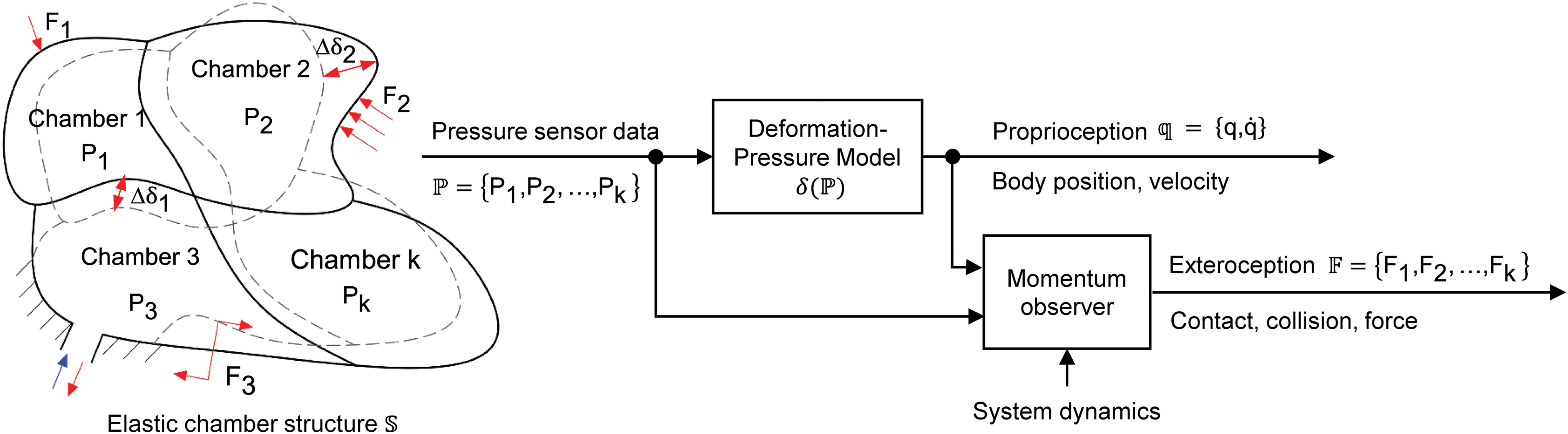
Mechanoreception concept for soft bodied system. Color images are available online.
Notably, compared with the state-of-the-art solutions with dedicated sensors, the proposed method only uses readily available pressure sensors. The practicality of external mechanical sensing based on pressure sensors has been already explored, including the commercialized biomimetic tactile sensor BioTac® (SynTouch LLC) that adopted the pressure sensors to detect slip-related microvibrations,28,29 tactile array sensor customized by inexpensive barometric pressure sensors, 30 and soft sensors composed of a sensing body and a pressure sensor for contact force and object curvature measurements. 31 However, these ideas did not tackle the problem of proprioception or the situation that body movements coexist with external mechanical stimuli, which is the aim of the mechanoreception scheme proposed in this study.
Design and Characterization of a 1-DoF Soft Pneumatic Bellows Actuator
To endow pneumatic soft robots with mechanoreception, the prominent challenge is that the actuated pneumatic pressure and the resultant pressure from environmental interaction are coupled. In this section, a 1-DoF soft actuator is proposed with antagonistically configured dual pneumatic chambers, each embedded with a pressure sensor. The two simultaneous but independent pressure feedback can provide sufficient information to distinguish between the internal status and external stimuli.
Antagonistic design of a soft actuator with bellows structure
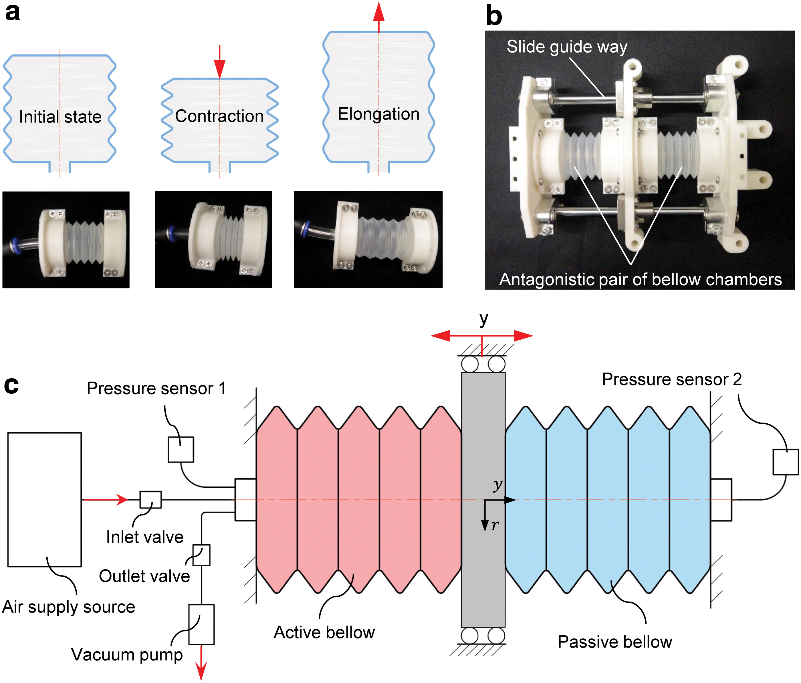
In terms of the structure, we constructed the soft actuator with two antagonistic V-shape circle-round-type bellows chambers.32–37 Among inflated soft robotic actuators, bellows chambers have been widely employed for their simplicity and sensitivity to single-DoF deformation.38–43 The bellows chambers used in this study concentrate elongation/contraction motion in the axial direction. Figure 2a shows the overall deformation of a bellows chamber.
Design of the proposed antagonistic bellow actuator:
For simplicity of derivation without losing generality, a 1-DoF linear soft pneumatic actuator with dual bellows chambers was proposed to verify the proposed concept. The bellows chambers were constrained antagonistically along the axial direction as shown in Figure 2b and the operating principle is illustrated in Figure 2c. In the proposed dual chambers design, an active bellows chamber was connected to a pressure sensor and the air supply line, whereas a passive bellows chamber was connected to a second pressure sensor only. By regulating the supplied pressure to the active bellows chamber, the position of a slider connected to the two chambers can be controlled. The inner pressure of the passive bellows chamber accounted for the length and movement velocity of the bellows chamber and, therefore, played a vital role in proprioception. External mechanical stimuli along the axial direction can be obtained by using the inner pressures of the active and passive bellows chamber synergistically.
Analytical modeling of bellows chambers
The mechanical property of the bellows chamber is of critical significance as it indicates how mechanical cues are encoded by the proposed structure into pressure signals. The deformable bellows chamber could both be actuated or react to external mechanical stimuli; thus, the inherent stiffness of the bellows structure is a fundamental quantity in decoupling them. Therefore, the axial stiffness of the bellows chamber was modeled to reveal the ingenuity of the antagonistic structure for addressing the nonlinearity problem.
The deformable bellows chamber used in this study was fabricated with low-density polyethylene (LDPE) by blow molding. The structural and material parameters of the LDPE bellows are presented in Table 1.
Structure and Material Parameters of the Bellow Chamber
Considering that all V-shape convolutions of the bellows are identical, as shown in Figure 3a, we first consider the relationship between the axial load and the deflection of one V-shape convolution. In this case, the inner circular edge of one end is clamped and a dummy axial load F is introduced, distributing uniformly around the circumference of the other end, as illustrated in Figure 3b. Consider a sector
From the static analysis shown in Figure 3c,
Hence
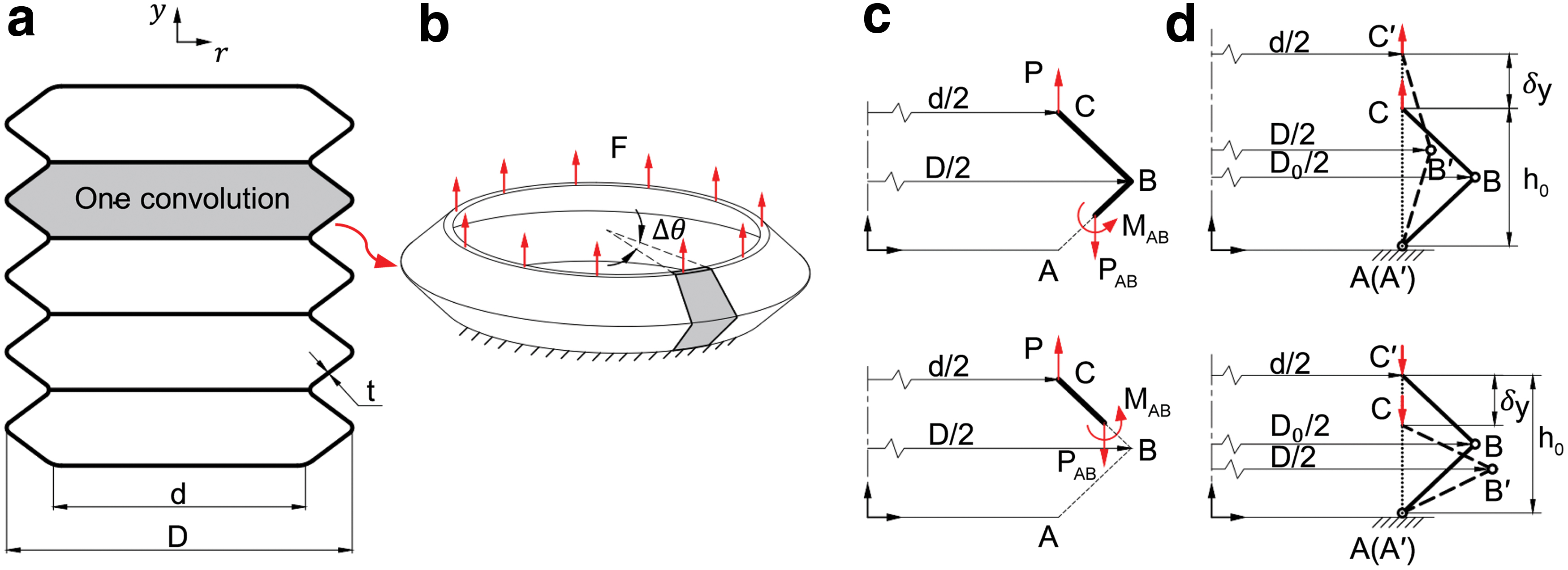
Axial stiffness analysis of the bellow structure.
Solving the integral equation in Equation (2), the axial deflection
where
Multiplying by N gives the total axial displacement y for a bellows with N convolution under axial load F,
Note that the displacement of the bellows is defined as positive when elongated and negative when compressed.
From Equation (4), the axial stiffness ky could be written as
The axial stiffness of the bellows is a function of four structural parameters, N, d, t,
From the simplified geometry model, we have
Solving Equation (6), the relationship between the ratio
Consider the following two boundary conditions:
The V-shape bellows chamber is elongated to a cylindrical shell with diameter d. In this case, the bellows chamber is mainly under tensile deformation rather than bending deformation. The axial stiffness becomes steeply large.
The V-shape bellows chamber is compressed to the situation that the adjacent convolution adheres to each other. The axial stiffness exhibits a sudden surge as it switches from bending deformation to compression deformation.
The bellows chamber can be deformed between these two boundaries. By calculating the displacement y of the two boundary conditions, the workable displacement range can be obtained as
Thus, within the workable displacement range, the outer diameter and inner diameter ratio
Equation (7) shows that in the workable displacement range, the outer diameter and inner diameter ratio
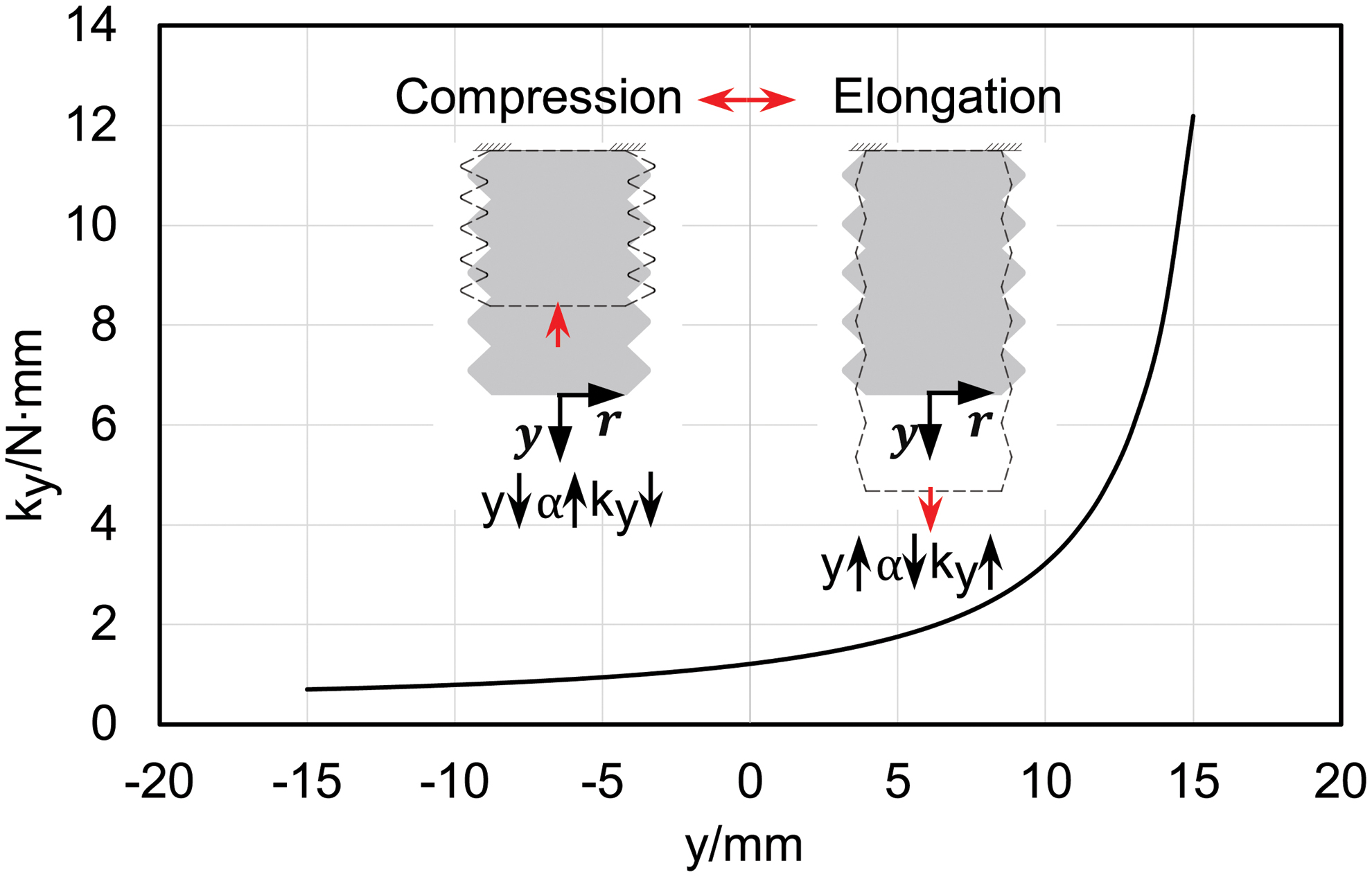
Nonlinear trend of the axial stiffness for bellow structure with parameters d = 25 mm, t = 0.5 mm, N = 5, D0 = 32 mm, and h0 = 6 mm. Color images are available online.
The nonlinear characteristics of the axial stiffness of the bellows structure will cause difficulties in further modeling. However, the introduction of dual antagonistic bellows contributes to the linearization. By exploiting the structural symmetry, the axial stiffness of the antagonistic actuator denoted as ka can be obtained as

The workable displacement of the antagonistic bellows actuator becomes
For the antagonistic structure, when one bellows is being elongated with increasing stiffness, the other one is being compressed for the same axial displacement with decreasing stiffness. Hence, the overall effect of deformation on actuator stiffness is reduced by the proposed antagonistic design. As shown in Figure 5, the work stroke of the antagonistic bellows actuator corresponds to the middle interval of the workable displacement range, thereby achieving approximated linear stiffness. The analytic model of the antagonistic structure is substantially simplified because of the reduced nonlinearity. The desired working stiffness could be obtained by optimizing the structural parameters N, t, d, D0, and h0.

Approximately linear trend of the axial stiffness for antagonistic bellow structure in work stoke (solid curve) compared with the nonlinear trend of the axial stiffness for single bellow structure (dotted curve) with parameters d = 25 mm, t = 0.5 mm, N = 5, D0 = 32 mm, and h0 = 6 mm. Color images are available online.
By denoting the axial load of the bellows as
Let g be the nonintegrable function defined by
In practical design, the difference between the outer and inner diameters is small, hence the term
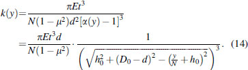
Substituting Equation (14) into Equation (12), the relation between the axial load
Similarly, we could obtain the relation between the axial load
Figure 6 illustrates the general trend between the axial load and displacement characteristics of a single bellows structure and the antagonistic bellows structure with parameters d = 25 mm, t = 0.5 mm, N = 5, D0 = 32 mm, and h0 = 6 mm.

The axial load and displacement characteristics of single bellow structure (dashed curve) and antagonistic bellow structure (solid curve) with parameters d = 25 mm, t = 0.5 mm, N = 5, D0 = 32 mm, and h0 = 6 mm.
Mechanoreception Scheme
The antagonistic bellows actuator consisted of one active bellows chamber connecting to the air supply source for active pneumatic regulations, and a passive one that was sealed for pressure monitoring only. By inflating or deflating the active bellows chamber, the pressure differential between the active bellows chamber and passive bellows chamber could drive the slider connecting the two bellows chambers along the guide. Accordingly, the pressure changes in the sealed passive bellows chamber could provide feedback on the actuator deformation. External mechanical stimuli acting on the slider would also induce axial compression or elongation of the two bellows chambers. Pressure changes in the two bellows chambers can be observed and varied under both internal and external mechanical stimuli. To distinguish the internal and external stimuli, the proprioceptive sense of actuator displacement can be achieved first from the pressure measurements of the sealed passive bellows chamber. With the status of actuator deformations being obtained, the external force can then be decoded by incorporating system dynamics.
Proprioception in actuator displacement
For a sealed chamber with an ideal gas, pressure and temperature within the chamber are assumed to be uniformly distributed, and the kinetic and potential energy of the air is negligible. Based on Boyle's law, we can obtain
where P is the pressure of the gas, V is the volume of the gas, and k is a constant.
From Boyle's law, the volume is inversely proportional to internal pressure for a fixed amount of gas kept at a fixed temperature. Thus, it can be used to predict the changes in volume by measuring the changes in pressure. For a sealed bellows chamber with one end fixed and the other end deforms along the axial direction, the volume of the bellows chamber can be obtained based on the simplified geometry model proposed in the last section:
where
Given the initial volume V0 and pressure
Therefore, the axial displacement of a seal bellows chamber can be indicated by its pressure through the following equation:
When it is under the actuating movement only or coexisting with external mechanical stimuli along the axial direction, the actuator displacement can be mapped by the pressure of the passive bellows chamber,
Dynamic exteroceptive contact force estimation
To better demonstrate the implementation of mechanical stimuli detection, a two-fingered gripper actuated by the antagonistic bellows actuator is presented in this section. As the end-effector of the robot manipulator, grippers are of fundamental importance in performing physical interactions with the environment. Integrated with the proposed antagonistic bellows actuator, the gripper was endowed with inherent adaptability and compliance. It would be an ideal exemplar to showcase how actuator-level detection of external mechanical stimuli was achieved when the gripper performed unstructured grasping tasks.
The mechanism of the proposed soft-rigid hybrid gripper is illustrated in Figure 7. The gripper was constructed with two symmetric 6-bar linkage with link 2 and link

Schematic diagram of gripper system integrated with the antagonistic bellow actuator. Color images are available online.
Nomenclature of the Gripper System
A momentum-based disturbance observer was introduced and extended to the gripper system for external force estimation.9,47,48 The observer assumed the presence of force/torque disturbances in the joints, which was considered to be produced by the 1-DoF grasping force at the gripper fingertips. Including the disturbance force, the dynamic model of the gripper system expressed by the generalized coordinate
where
where ka is the stiffness of the antagonistic bellows structure, y is the displacement of the antagonistic bellows actuator. Here
where Fa is the actuation force applied on the slider, which can be estimated by the measured pressure P1 and P2 of the active and passive bellows chambers as
According to the dynamic model, the external contact force Fe could have been estimated using position
Taking the first-order derivative over time,
Substituting Equations (23) and (26) into Equation (28) yields
Based on the expression of dynamics of p and denoting
where the residual
The residual dynamics can be obtained as
With
It is observable that the residual r would approach the external force by choosing a very large observer gain KO. Using Equations (29) and (30), the residual r can be obtained as

with

Schematic overview of the momentum observer.
Finally, the external grasping force acted on the gripper finger along x-axis can be estimated by
Evaluation Experiment and Calibration
Force and displacement characteristics of the bellows structure
A test apparatus was dedicatedly built to characterize the mechanical property of the bellows structure as shown in Figure 9. According to the boundary constraints in the analytical model, the inner circular edge of the bellows was clamped by a rigid fixture. In the single bellows test, one end of the bellows was fixed, whereas the other end was free by connecting to a slider as illustrated in Figure 9a. In the antagonistic bellows test, the free ends of the two bellows were antagonistically connected to the slider as shown in Figure 9b. A linear motion platform driven by a stepper motor (57BYGH301AA, 200 steps per revolution) was employed to exert tensile or compressive force to the bellows by connecting the guide bearing of the linear motion platform to the slider. A load cell (±100 N max.) was mounted between the slider and the guide bearing of the linear motion platform to measure the axial force applied on the bellows structure. The free rod of a linear position sensor (KPM16, 75 mm max.; MIRAN Ltd.) was connected to the guide bearing of the linear motion platform; thus, the axial displacement of the bellows structure was recorded. The structural parameters of the bellows specimens were d = 25 mm, t = 0.5 mm, N = 5, D0 = 32 mm, and h0 = 6 mm.

Experimental setup for test of axial force and displacement characteristics of
To validate the analytical models, quasi-static tensile/compressive tests of the single bellows structure and the antagonistic bellows structure were conducted, respectively. Each test was repeated three times on the same bellows structure for repeatability validation. The resulting data of the repeated tests were compared with the analytical model in Figure 10, with the force predicted by the analytical model smaller than experimental measurements. This was probably due to the use of smaller stiffness values based on Taylor approximation. Nevertheless, both models proposed for single bellows structure and antagonistic bellows structure could capture the overall trend of the experiment results and effectively predict the axial force and displacement characteristics of the bellows structure. Particularly, the experimental data of a single bellows structure exhibited repeatable nonlinear pattern, whereas the antagonistic bellows structure showed improved linearity between the axial force and displacement. Least square curve fitting was conducted on the test data of antagonistic bellows structure in the working stroke interval with
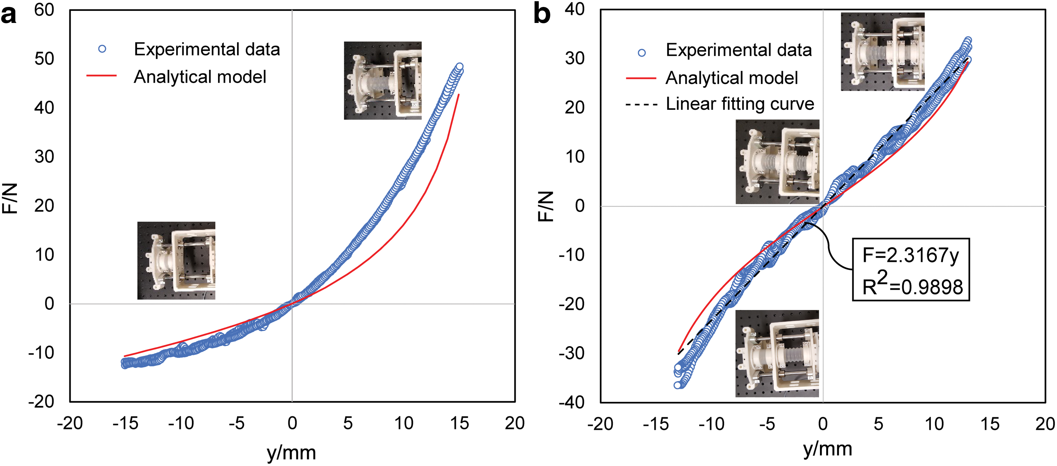
Axial force and displacement characteristics of
Calibration for actuator displacement sensing
A key step of the proposed mechanoreception scheme was to estimate actuator displacement using the measured air pressure in the actuator chambers. However, this required the initial volume and initial pressure of the bellows chamber. Although the latter could be measured by the pressure sensor, the former had to be determined through calibration. A calibration experiment was conducted to identify the parameter of the displacement estimation model. As shown in Figure 11a, the same test apparatus was employed to apply the tensile or compressive deformation on the sealed bellows chamber connected with a pressure sensor (XGZP6847300KPGPN, range: −100 to 300 kPa; CFSENSOR Ltd.). The actual displacement data was captured by the linear position sensor (KPM16, 75 mm max.; MIRAN Ltd.) and the corresponding pressure was recorded by the pressure sensor. The experiment was repeated three times for reliability.

Calibration experiment of actuator displacement sensing.
According to the proposed estimation model for displacement from pressure,
To calibrate the parameter S, the pressure data P can be transformed to the ratio of the pressure change with respect to the initial pressure and the current pressure
where P0 is the initial pressure of the bellows chamber.
The results of the calibration experiment are presented in Figure 11b, with the actual displacement against the ratio
To validate the calibration results, further experiments were carried out for actuator movement prediction, with results presented in Figure 12. In this experiment, movements of the antagonistic actuator were generated arbitrarily across the entire working range by inflating and deflating the active bellows chamber. The pressures of the two bellows chambers (P1 and P2) were tracked by the pressure sensors. Displacement of the actuator (ym) was measured by a linear position sensor and compared with the estimated value of the actuator movement (y) from the calibrated model. From the result shown in Figure 12b, the maximum absolute error between the measured and estimated displacement was 0.95 mm, with a mean of 0.238 mm and a standard deviation of 0.236 mm. The accuracy was sufficient in grasping tasks of general daily objects and contributed critically to the estimation of external contact forces.
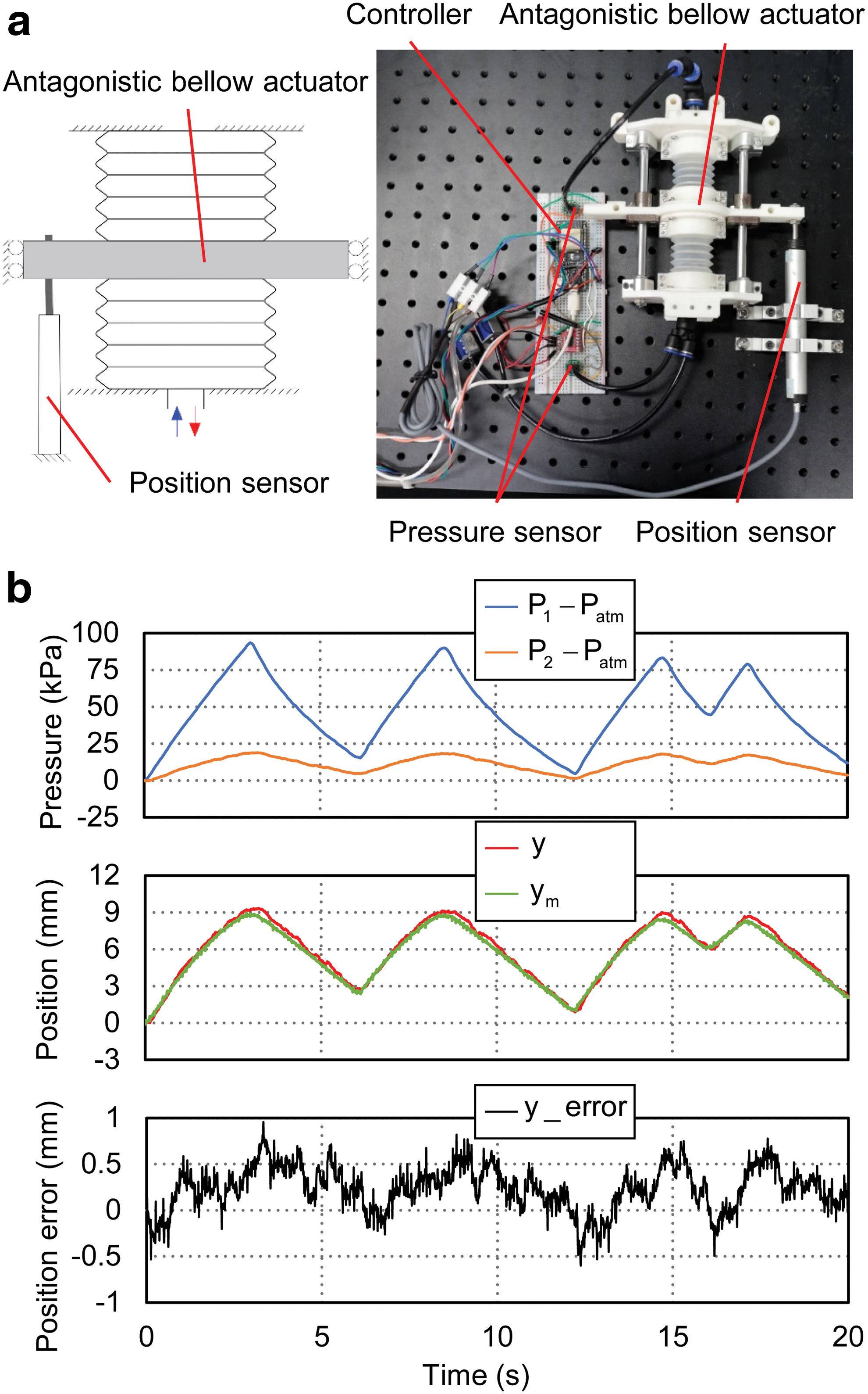
Validation experiment of actuator movement prediction.
Experimental evaluation of external force estimation model
The proposed model for external contact force estimation was validated in an experiment when actuated movements and external mechanical stimuli were applied simultaneously. In the experiment, as illustrated in Figure 13a, the soft gripper was actuated to pinch a standard elastic object (a spring) by applying arbitrary gripping forces. A load cell was mounted onto one finger to record the contact force with the spring attached to the opposite finger.

Validation experiment of external force estimation model.
The experimental results are presented in Figure 13b, showing the inner pressure of the active (P1) and passive (P2) bellows chambers, the estimated position of the actuator y and measured position ym, the actual contact force Fm measured by the load cell and the estimated contact force Fe from the derived models. The maximum error between the momentum observer estimation and the measured external force was 2.181 N, with a mean of 0.189 N and a standard deviation of 1.233 N. Some working-range correlated trends could be observed in the estimation error, which was possibly due to the model reduction and actuator hysteresis. In general, the estimation model performed well for the targeted purpose of obtaining the interactive force without requiring a dedicated force sensor. With the validated estimation accuracy, in future experiments, a reference force sensor was not used, as it would significantly interfere with the object grasping operations.
Mechanoreception Experiments
In the final stage of validation, the prototyped soft-rigid hybrid gripper integrated with the antagonistic bellows actuator was tested by a series of object grasping experiments. A pneumatic control system was set up to drive the gripper with an air supply and two solenoid valves, one for inflation and the other for deflation. Two pressure sensors were connected to the bellows chambers to provide pressure feedback to the controller to determine the corresponding on/off states of the two solenoid valves, thus controlling the two fingers of the gripper. To fully demonstrate the mechanoreception capability of the gripper system in a practical setting, the gripper was mounted to a 6-DoF robotic manipulator arm (E6; SANTIFICO Ltd.) as shown in Figure 14.

Prototype of the soft-rigid hybrid gripper with simple control system. Color images are available online.
In this section, to showcase the different features of the proposed mechanoreceptive gripper under different forms of mechanical stimuli, two kinds of interactive contacts are covered: active exploratory interaction and passive contact.
Active exploratory interaction
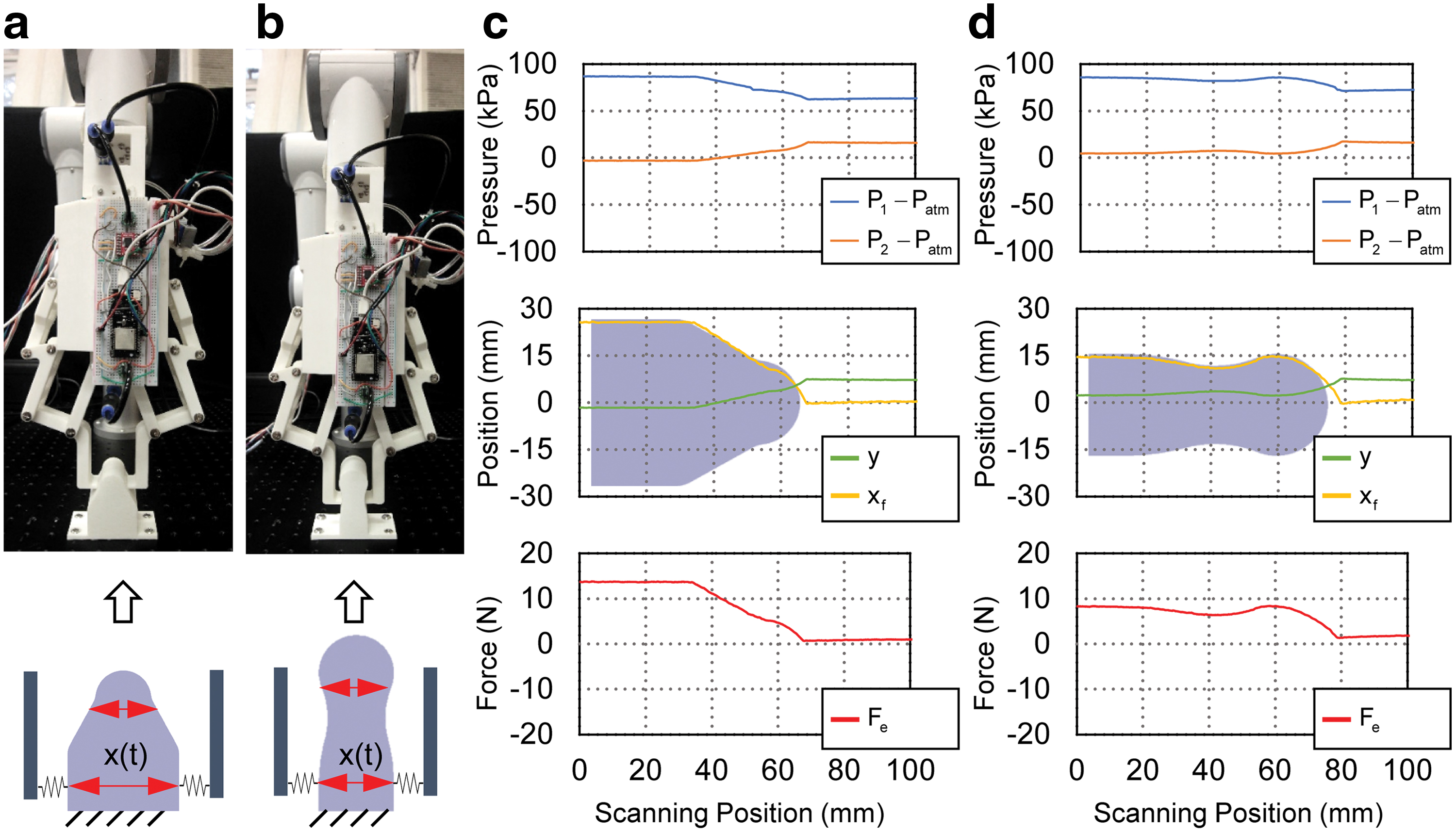
With mechanoreception, the proposed gripper was capable of both contact detection and external contact force estimation. To highlight this capability, we demonstrated the gripper with a highly challenging task of object stiffness identification through a single grasping action. To illustrate the principle and implementation of object stiffness identification, the experimental results of grasping a low-density sponge (phase

Stiffness identification of low-/medium-density sponges by single grasping. Top plots: pressure of the active P1 and passive P2 bellow chambers; middle plots: estimated actuator displacement y and right fingertip position xf; bottom plots: the estimated external contact force Fe. Color images are available online.
A group of six different objects, each with distinctive deformation properties, were used to further showcase the haptic sensing capability of the proposed gripper based on the same principle discussed earlier: (1) a rigid three-dimensional-printed cube (PLA material), (2) a spring (304# steel), (3) a bellows chamber (LDPE), (4) a low-density sponge, (5) a medium-density sponge, and (6) a high-density sponge. As shown in Figure 16a, the force-deformation scatter plot of the six objects were generated by recording the relative change of fingertip position and estimated contact force relative to the contact point. In general, the gripper system effectively painted the stiffness characteristics of the objects by a single grasping action without either a dedicated position sensor or force sensor.

Force and deformation characteristics of six different objects explored by the gripper system by single grasping.
Passive mechanical stimuli detection
The scenario that the gripper was under the equilibrium state without active movements had also been considered. In this case, both the two bellows chambers of the actuator were sealed and the gripper system passively received the mechanical stimuli from the environment. In the first experiment, as shown in Figure 17, the two fingers were squeezed or force-opened by hand, while the changes of pressures in the two bellows chamber, the estimated position, and external contact force were recorded. During squeezing the active bellows chamber was elongated, whereas the passive bellows chamber was compressed. Hence, pressure in the active bellows chamber decreased, whereas the passive chamber pressure increased, that is,

Experimental behavior of the gripper system when the two fingers being passively squeezed and opened.
A straightforward application was contact loss detection in object grasping. This provided the robot control system binary feedback that whether the object was successfully grasped or dropped from the fingers due to slippage, disturbances from robot arm movements, or other causes. We conducted two preliminary object grasping experiments during which contact losses were induced by tugging out manually the object held by the gripper fingers. As shown in Figure 18, the gripper was inflated at a pressure of 230 KPa to ensure successful grasping of the object in phase

Experimental behavior of contact loss detection in object grasping.
Another interesting application was object contour scanning. In this application, the gripper was equipped with two new fingers designed with rounded tips. The robot arm was used to guide the gripper to scan a symmetrical tapered surface and a symmetrical waved pattern along Z-axis as shown in Figure 19a and c. Starting by clamping one end of the surface with enough gripper force, the two rounded fingertips were passively opened or closed with guided movement along Z-axis, conforming to the scanned surface. By recording the fingertip position xf, the contour of the surface can be traced. The experimental data of the two tested surfaces are shown in Figure 19b and d, respectively, exhibiting good matching with the real contour of the measured objects.
Object contour scanning experiments.
It is worth mentioning that the aforementioned experiments demonstrating passive mechanical stimuli detection showcased the advantages and potential of the inherent compliance and adaptability of soft robots. In particular, in object contour scanning, the passive compliance of the proposed elastic actuator was cunningly leveraged. In addition, an inherently compliant and adaptive actuator endowed with mechanoreception is highly promising in haptic exploration and dexterous manipulation tasks.
Conclusions and Future Study
In this study, we provided a new scheme to endow soft pneumatic robots with proprioceptive sense in signaling body movement and the capability of exteroceptive contact detection. The concept was implemented and validated on a soft-rigid hybrid gripper system driven by a 1-DoF pneumatic bellows actuator. We demonstrated theoretically and experimentally that both actuator displacement and external contact force can be decoded simultaneously based on static and dynamic models and the pressure measurements of the bellows chambers. Notably, it was demonstrated that the proposed soft-rigid hybrid gripper endowed with mechanoreception could obtain quantitative understandings of the external environment (e.g., object stiffness and contour) without requiring dedicated sensors.
It is worth noting that the sealed chamber, in addition to the active chamber, was the key to providing a reference that enabled higher-level position and force estimations. The gas pressure sensors, on which the proposed mechanoreception scheme was based, were typically available in most soft pneumatic robots with deformable chambers for basic control. In light of this, the proposed mechanosensory scheme can be generalized to those soft extending and contracting actuators and can be of reference significance for the future development of smart soft robots.
There are two aspects of limitations regarding the proposed approach that can be addressed in future research. The working range was limited to the linearized stroke interval of the proposed antagonistic actuator, which restrained the overall performance of the gripper system. In future study, remedies to release this constraint will be sought to increase the working stroke in spite of the nonlinearity. Owing to the performance limitations of the soft actuator, this study was focused on 1-DoF linear motion. We will make efforts on the improvement of soft actuator design and extending the mechanosensory exploration to multi-DoF systems in future study. Both directions can substantially contribute to the generalizability of the proposed mechanoreception scheme for a wider range of soft robotic designs and systems.
Footnotes
Author Disclosure Statement
No competing financial interests exist.
Funding Information
This work was partially supported by Hong Kong ITF Grant ITS/140/18 & ITS/457/17FP, HKU Seed Funding 201711160023 & 201711159158, and NSFC Grant 51975268.