
Abstract
In recent years, soft components, such as pneumatic artificial muscles (PAMs), have been increasingly employed to design safer wearable devices. Despite the inherent compliance of the materials used to fabricate PAMs, the actuators are able to produce relatively large forces and work when compared to their weight. However, effective operation of these systems has traditionally required bulky external force and position sensors, which limit the maneuverability of users. To overcome these issues, inspiration was taken from organic muscles, which incorporate embedded sensors, such as Golgi tendon organs and muscle spindles, to provide real-time position and force feedback for muscles. As such, a sensorized, flat, pneumatic artificial muscle (sFPAM) with embedded force and position sensors was designed and fabricated. In addition, a hyperelastic model was developed and verified through comparison with the experimentally characterized mechanical and electrical performance of the sFPAM. Furthermore, a sliding mode controller was implemented to demonstrate the feasibility of embedded sensors to provide feedback during operation. Ultimately, a lightweight, compact actuation system was designed with the ability to be seamlessly incorporated into future wearable devices.
Introduction
Technological advances in robotic systems have led to development of cheaper more robust designs that are increasingly becoming everyday aspects of modern society. These systems encompass a plethora of applications, including autonomous vehicles, teleoperated medical devices, toys for children, personal robots, and wearable devices. An important consideration for researchers in this field centers on human–robot interactions, which seek to foster safe and efficient working relationships and environments.1–8 This is particularly important in the design of wearable robotic devices due to the higher risks involved with linking the mechanics of the human body to an external system. Thus, researchers have sought to produce safe and efficient systems through implementation of complex control algorithms and innovative system designs.3–7,9
One such innovation, which is particularly important to this study, can be found in the use of pneumatic artificial muscles (PAMs) in the design of wearable devices.10–14 PAMs, which traditionally comprise soft elastomeric bladders constrained by flexible, but inextensible, mechanisms, have increasingly been used in the field of robotics due to their favorable characteristics.15–17 PAMs comprise soft materials, which typically have elastic modulus and stiffness values in the range of organic tissue, making them safe when interacting with humans.18–20 These materials allow PAMs to remain lightweight and compliant, while being able to generate large forces when compared with that of their own masses. In addition, when pressurized, PAMs generate linear displacements and forces that can be utilized to produce desired movements. Despite the aforementioned properties of PAMs, operation of these actuators is complicated due to their nonlinear response to input pressure.
To overcome this caveat, designers have employed various external and internal sensors to detect the current state of actuators during operation. However, current designs fall short of ensuring effective real-time control of compliant and compact designs. External sensors, including linear force gauges and encoders, increase bulkiness and add undesirable rigidity to the overall system. Meanwhile, internal sensors, such as embedded conductive elements in the elastomeric air chamber for resistive sensing for detecting shapes21–23 and contacts,24,25 or integrated braided conductive wires to the outer mesh structure for inductive sensing26,27 have not allowed for multimodal proprioceptive sensing, such as detection of contraction displacement and force simultaneously, due to difficulties arising from complex fabrication processes. A solution to this issue, however, can be found in biological muscle systems, which operate similarly to PAMs.
Biological muscle, an organic soft tissue, is lightweight, compact, and capable of generating linear forces and displacements when stimulated by electricity. Muscles, which are typically found in antagonistic pairs throughout the human body, comprise millions of contractile microunits known as sarcomeres that are connected in series and in parallel to provide human-scale contractile forces and displacements. Although muscle contractions may be voluntary (consciously controlled) or involuntary (subconsciously controlled), both neurological control schemes employ embedded organic sensors to detect the current state of the muscle. These sensors, known as mechanoreceptors, detect the stretch, length, and tension of muscle fibers, without increasing the muscle's overall form factor. The primary muscular sensory receptors are the muscle spindles and Golgi tendon organs.28,29 The muscle spindles are located along muscle fibers (contractile region of muscles) and serve to detect the overall length of the muscle, while the Golgi tendon organs are located in muscle tendons (terminals of muscle) and detect the muscles' generated stress (Fig. 1). These sensors work in unison to provide the human body with a continuous stream of sensory data that are used to provide effective motor control of the muscle systems.

Schematic comparison of sFPAM with biological muscle. sFPAM, sensorized, flat, pneumatic artificial muscle.
In seeking to replicate the properties of biological muscles and their sensors, this study focuses on the design, control, and experimental characterization of a biologically inspired integrated sensing and actuation system comprising a PAM with embedded sensors (Fig. 1). The proposed design utilized a modified version of the flat, pneumatic, artificial muscle (FPAM) design10,30 due to the simple, layered fabrication method employed as well as the ease with which multimodal sensing could be incorporated. The main research contributions of this study are (1) the design and characterization of a bioinspired PAM with multimodal sensing (force and position), (2) proposition of a new manufacturing method that significantly improves repeatability and automation of the fabrication process, and (3) introduction of hyperelastic deformation models to the analysis of FPAMs for improved prediction of both actuator force and displacement.
The remainder of this study is organized as follows: we first describe the design features and fabrication process of the sensorized, flat, pneumatic artificial muscle (sFPAM), followed by analytical modeling. Then, we present experimental results of characterization of both the actuator and sensors and the feedback control. Finally, we conclude with implications and future work.
Design
In this study, the sFPAM, a novel pneumatic actuator with embedded sensors, was designed and fabricated. A modification to previous fabrication techniques for the manufacture of FPAMs was made through substitution of a patterned, laser-cut plastic sheet, which served an integral role in the design of the overall sFPAM system, as shown in Figure 2. The previous FPAM design was a thin rectangular actuator comprising a liquid core silicone rubber substrate that contained embedded Kevlar fibers.10,30 The effects of the elastic substrate being constrained by the flexible, but inextensible, fibers during pressurization of the PAM's zero-volume air chamber (ZAC) resulted in generation of linear forces and contractions.10,30 This study further improved on the effectiveness of the previous design through modifications to incorporate embedded multimodal sensing and to improve the repeatability of the fabrication process. This was accomplished through substitution of Kevlar fibers with a laser-cut, flexible plastic sheet (PEI Ultem; McMaster Carr), addition of a noninflatable terminal to the actuator design, and incorporation of microchannel negatives into the layer molds for both force and contractile sensing.
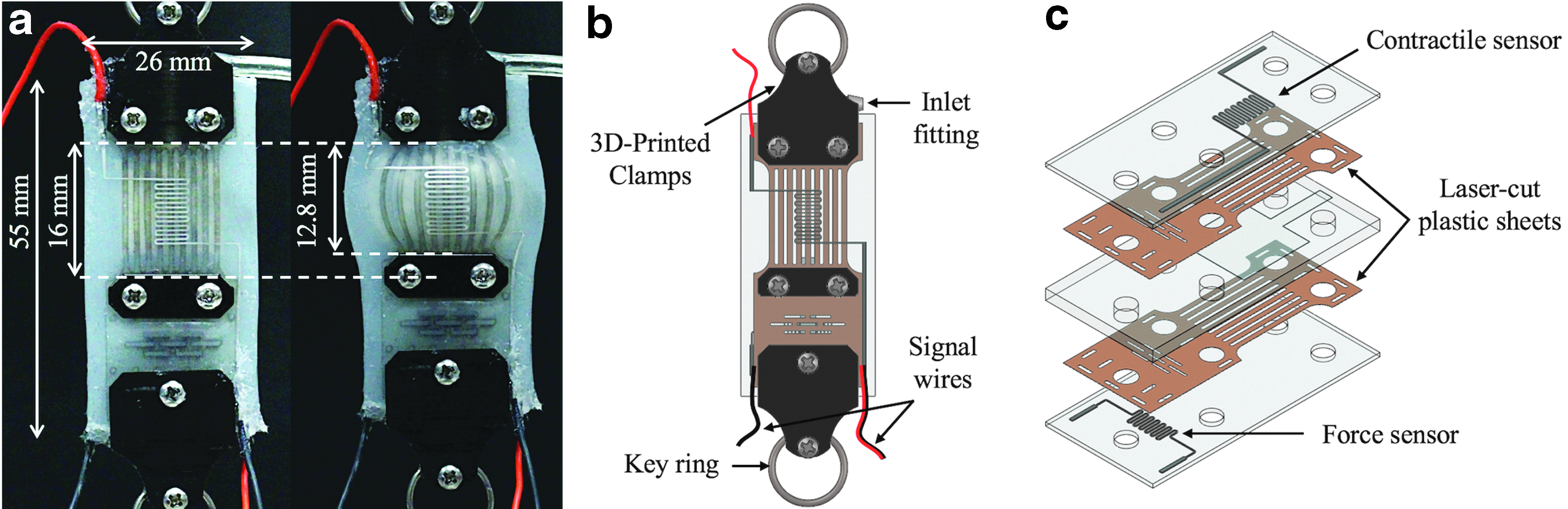
These alterations allowed for design of the sFPAM with a constant stiffness tendon and deformable muscle, which contained a bioinspired Golgi tendon organ and muscle spindle fabricated using eutectic gallium–indium (eGaIn), an extensively studied, conductive liquid metal31,32 that has been embedded as a resistive sensor in various soft robotic systems.33–36 In particular, the laser-cut flexible sheet was integral to the current actuator design. Substitution of the sheet for Kevlar fibers minimized misalignment issues that led to slack and allowed for more rapid manufacturing of the desired sheet design. Additionally, a Kirigami design37,38 with the woven dashed-line pattern perpendicular to the contraction direction (Fig. 2b) made at the terminal tendon section of the sheet provided minor stretchability, which allowed the force sensor to change values during operation.
The proposed sFPAM was fabricated using a simple, layered manufacturing process. The fabrication process, Figure 3, makes use of liquid silicone rubber and photopolymer (VeroBlack; Stratasys) molds, which were made using a three-dimensional (3D) printer (Objet30; Stratasys) to create two layers (thin silicone sheets) and a core (central substrate containing the ZAC) with an embedded water-soluble mask (Water Soluble Stabilizer, Paper Solvy). The mask is removed using water to create the ZAC. The layers were fabricated with embedded microchannels that were filled with eGaIn purchased from Alfa Aesar to act as resistive, liquid metal contractile and force sensors. Afterward, the layers and core were stacked and bonded together to form the base actuator in the following order: silicone layer (force sensor), laser-cut plastic sheet (PEI Ultem; McMaster Carr), core, laser-cut plastic sheet (PEI Ultem; McMaster Carr), and silicone layer (contractile sensor). Finally, an inlet fitting (5463K41; McMaster), flexible wiring (9564T3; McMaster), and 3D printed clamps were then added to complete the actuator. A prototype of the PAM can be found in Figure 2a. The base single-cell actuator was made using Dragon Skin 10 silicone rubber (Smooth-On, Inc.) and had dimensions of 55 × 26 × 5.5 mm thickness, with ZAC dimensions of 16 × 16 × 0.1 mm thickness, and weighed about 17 g. The microchannels (sensors) had cross-sectional dimensions of 0.2 × 0.2 mm thickness.

Fabrication process of sFPAM using a water-soluble mask:
Modeling
A theoretical model was previously developed using a modified von Karman formulation for large deformation of membranes and the energy method39–41 to approximate the mechanical performance of the FPAM. 30 In this study, the model was further built upon through introduction of hyperelastic, strain energy density formulations and geometric constraints. Initially, the sFPAM was modeled as two flat, elastic, rectangular composite sheets simply supported along their edges (Fig. 4). The z-axis deflection

Diagram of the top half of sFPAM depicted as a flat sheet under external force F and pressure P.
theorized by Timoshenko39,40 for elastic deformation of a simply supported membrane under uniform pressure, was utilized. Here, x and y are the positions from the center of the composite sheet parallel and perpendicular to the fiber direction, respectively, w0 is the maximum z-axis deflection, and 2a and 2b are dimensions of the sheet in the x-axis and y-axis directions, respectively. In a previous study analyzing deformation of the FPAM,
30
the final x-axis and y-axis displacement formulations
30
were solved as
where u0 is the maximum displacement in the x-axis direction and v0 is the maximum displacement in the y-axis direction. With the formulation of solutions for u(x,y) and v(x,y), in addition to w(x,y), displacement of any point in the composite sheet during elastic deformation was determined. Given that hyperelastic solutions should reduce to the elastic formulations, in their linear regime, it can be assumed that hyperelastic solutions take on a similar form as elastic solutions. As such, hyperelastic displacement formulations were assumed to take on the following forms:
where u0, u1, u2, v0, v1, v2, and w0 are unknown constants to be solved for through minimization of the system's potential energy, Π. To solve for these unknowns, a nonlinear, hyperelastic, strain energy density term, W, was incorporated. The composite sheets were assumed to be incompressible neo-Hookean solids with deformation tensor, B, and right Cauchy–Green deformation tensor, C, defined as
The strain energy density of a neo-Hookean solid is defined as the shear modulus multiplied by the first invariant, or trace, of the right Cauchy–Green deformation tensor, which resulted in the strain energy density formulation
with the resulting volumetric stretch ratio defined as
The normal stretches, λx in the x-axis direction, λy in the y-axis direction, and shear strain ɛxy, were defined as
while λz, the stretch in the z-axis direction, was found from the incompressibility constraint
Second, the deformed volume of the composite sheet had to be equivalent to the initial volume due to the incompressibility constraint. This was accomplished by defining the x, y, and z positions of the composite sheet as
Utilizing the relationships found from the applied constraints, the potential energy of the system could then be defined as
where
Experiments
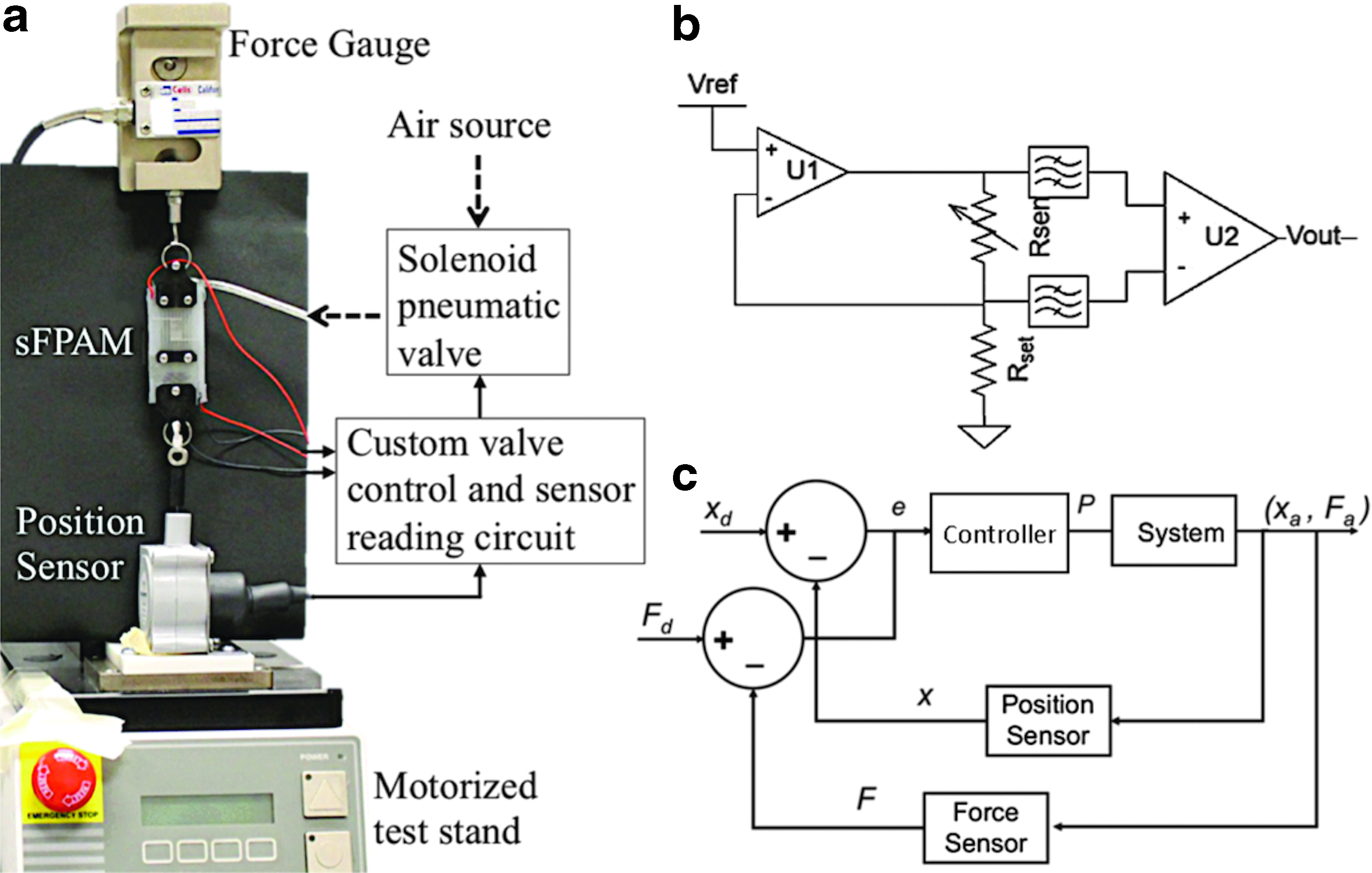
Three different sFPAM prototypes were subjected to experimentation to characterize overall actuation and sensing performance of the design, as well as demonstrate the feasibility for the sFPAM to be controlled. Experimental characterization was conducted using a single-axis, motorized test stand (ESM301; Mark-10) equipped with a single-axis load cell (STL-50; AMCells), a data acquisition unit (DAQ, USM-600; National Instruments), a pressure regulator with a pressure gauge measurable up to 200 kPa (McMaster Carr), a custom amplifier circuit, and a custom LabVIEW program designed to collect experimental data, as shown in Figure 5a. Using this experimental apparatus, the sFPAM was subjected to a set of experimental procedures to characterize the mechanical performance of the actuator and determine corresponding sensor data during operation. The actuators were pretensioned to 0.5 N before experimentation to minimize errors in actuator performance due to slack and/or differing initial conditions. After application of the aforementioned pretension, the actuators were subjected to tests to characterize the force versus contraction response, determine the maximum force generation and contraction with corresponding sensor data, and identify real-time effectiveness of sensors at pressures ranging from 0 to 82.8 kPa (above which failure occurs).
Characterization
The force versus contraction response characterization was conducted by installing a single sFPAM at rest in the experimental apparatus and holding it fixed (contraction = 0 mm). After the actuator was pretensioned, the LabVIEW program was tared. Subsequently, a constant pressure in the aforementioned pressure range was applied, inducing an increase in the force reading of the program. After the force reached a steady-state value, the sFPAM was then manually contracted at a speed of 10 mm/min until the LabVIEW program's force reading returned to zero. This procedure was repeated to produce the force versus contraction characterization of the sFPAM.
In the procedure to identify the maximum force output of sFPAMs due solely to pressurization of the air volume, the actuators were placed in the experimental apparatus and held fixed at their rest length (contraction = 0 mm) throughout the experiment. Following the application of pretension, the program was tared and actuators were pressurized from 0 to 89.7 kPa in increments of 6.9 kPa. At each increment, the force was allowed to settle to a steady-state value, at which point data were recorded for the maximum generated force and resistance change of both the force and contractile sensors.
The maximum contraction of sFPAMs was identified through experimentation in no-load conditions (applied force = 0). The actuators were placed on the experimental apparatus with one end free to move, but initially maintained physical contact with the base of the Mark-10 test stand. The Mark-10's distance measure was then tared. Subsequently, the actuators were pressurized from 0 to 89.7 kPa in increments of 6.9 kPa. At each increment, the actuators freely deformed due to the input pressure, contracting along the axial direction. The actuators were then lowered until their free ends once again contacted the base of the test stand. At this point, maximum contraction and resistance change of both force and contractile sensors were recorded.
The x-axis tensile modulus was also found experimentally. The actuators were pretensioned to 0.5 N before testing. Subsequently, the actuators were stretched to failure. Using the rule of mixtures, the effective fiber modulus was calculated.42,43 Results of these experimental procedures were then used to develop a controller for force and position control of the sFPAM.
Feedback control
A custom amplifier circuit was used to measure small changes in resistance of the sFPAM. This circuit drives the sensor with a precise reference current and measures the voltage across the sensor leads. Sensor resistance can then be calculated using Ohm's law:
This circuit allows for precise independent control of drive current and amplifier gain. Drive current is set based on the geometry of the sensor to avoid thermal effects. Next, the maximum amplifier gain is selected to maintain the output voltage within supply rails for the full range of the sensor.
This amplification circuit, alongside a microcontroller and two solenoid valves, was then used to implement a sliding mode controller. As seen in Figure 5c, the controller used both force and position as inputs. The sliding mode controller implemented a proportional control scheme that alternated between a large (KFL, KPL) and small proportional gain (KFS, KPS) for both force and position depending on the size of the error between the current state and desired state. This control scheme was chosen for simplicity to demonstrate that the feasibility of sFPAM could be controlled using its embedded sensors. During experimentation, the actuators were subjected to either a force or a position control test to determine the viability of the overall system to be controlled. During position control, the actuators were fixed to a stationary mount on one side and a linear position sensor on the other. The embedded sensor signals were amplified and sent to the microcontroller, after being calibrated, and used to implement the desired position control tests. During force control experimentation, sFPAMs were fixed at the force gauge on one end and a stationary mount on the other. After being pretensioned, the actuators were then subjected to the designed control algorithm. During both position and force control experiments, the force gauge and position sensor were used to provide base values for comparison of how effectively the embedded sensors performed during real-time operation.
Results
The experimental data collected for the sFPAM were utilized to characterize the mechanical performance of the actuator. In addition, the resulting resistance changes of contractile and force sensors were mapped to the mechanical performance to provide a relationship to be used for design and implementation of the controller. Figure 6 provides an example of the sFPAM force–contractile relationship at pressures ranging from 0 to 89.7 kPa. At pressures above 89.7 kPa, the actuators failed due to the laser-cut plastic sheet shearing during bending.

sFPAM force–contraction relationship at pressures ranging from 0 to 90 kPa.
Maximum contractions and generated forces of the sFPAM over the operational pressure range are found in Figure 7a and c. In addition, experimental values were compared with the theoretical model developed and showed close agreement.
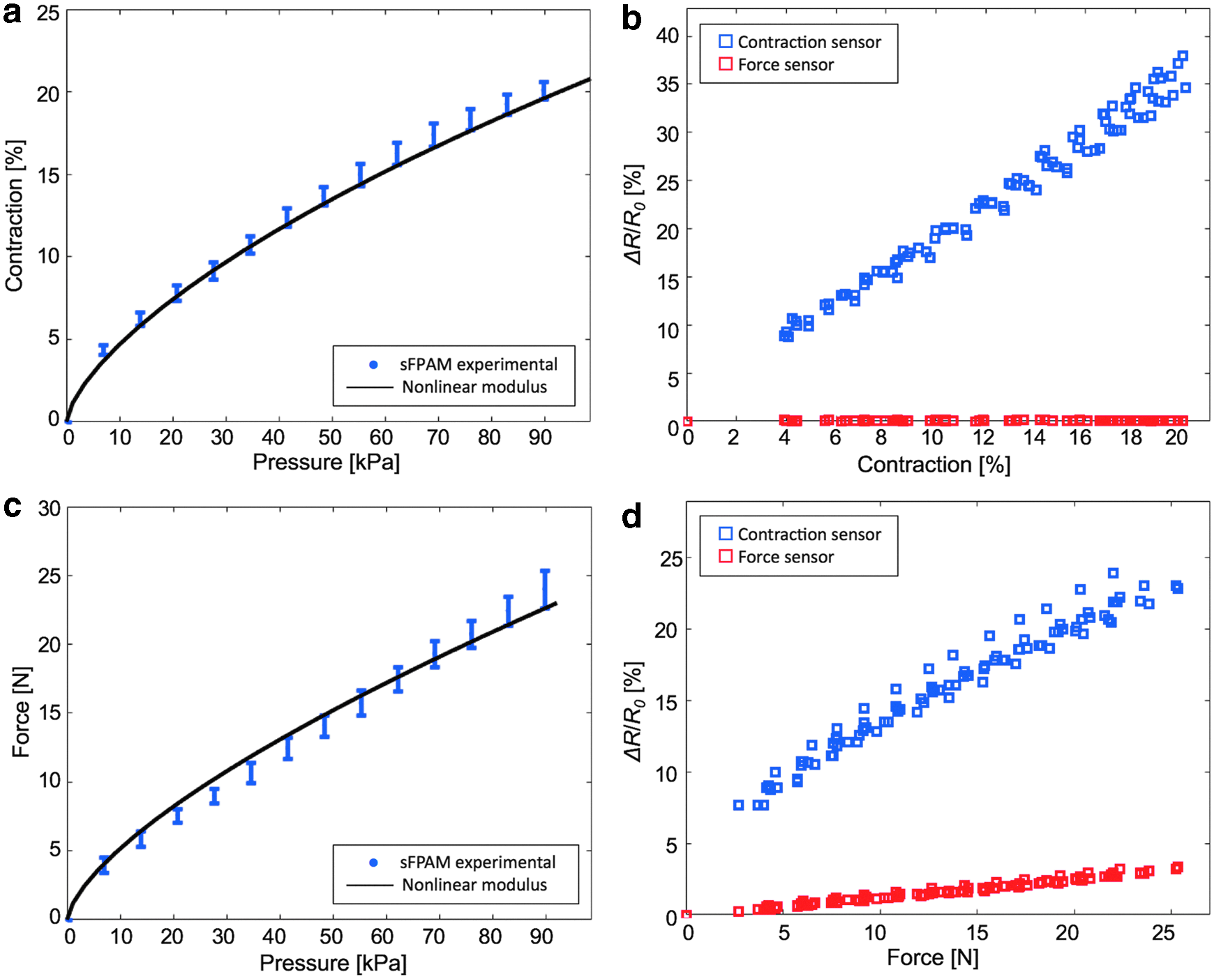
Overall, the sFPAM produced a maximum contraction of 19.8% ± 0.2% and maximum force of 24 ± 1.37 N. Theoretical model approximations predicted the contraction of the sFPAM to an average root mean squared error (RMSE) of 0.47% contraction (max RMSE 0.83%) and 0.68 N force (max RMSE 1.45 N). Additionally, the model accurately captured the trajectory of both contractile and force responses to input pressures. The corresponding sensor values can be found in Figure 7b and d. The effects of contraction on sensors specifically can be found in Figure 7b. As shown, the contractile sensor exhibited a linear response to input pressure when the sFPAM was allowed to freely deform to its maximum contraction. Overall, the contractile sensor changed 36.4% ± 1.2% in resistance, resulting in a resolution of 0.54% contraction to percent change in resistance. In addition, the force sensor remained nearly constant, maxing at a 0.15% change in resistance, which is less than 5% of the respective change due to the sFPAM's generated force. This result demonstrated that the force sensor was minimally affected by contraction and thus could be considered completely decoupled from the effects of contraction, which would be key to implementing effective control of the sFPAM in real-world applications.
The effect of force on sensors is found in Figure 7d. The force sensor changed 3.1% ± 0.2% in resistance and resulted in a resolution of 8 N of force to percent change in resistance. However, there was a more significant coupling between the contractile sensor and force generated by the actuator. Despite the sFPAM being held fixed during maximum force experiments, the air volume still deforms slightly in the z-axis direction, inducing a change in the resistive sensor that maxed out at 23.2% ± 0.4% resistance change. The change in the contractile sensor due to force is about two-thirds the respective change due to contraction for the actuator. However, because of the advantageous decoupling of the force sensor from contraction, as previously mentioned, the contractile sensor coupling could be readily alleviated during development of the control algorithm.
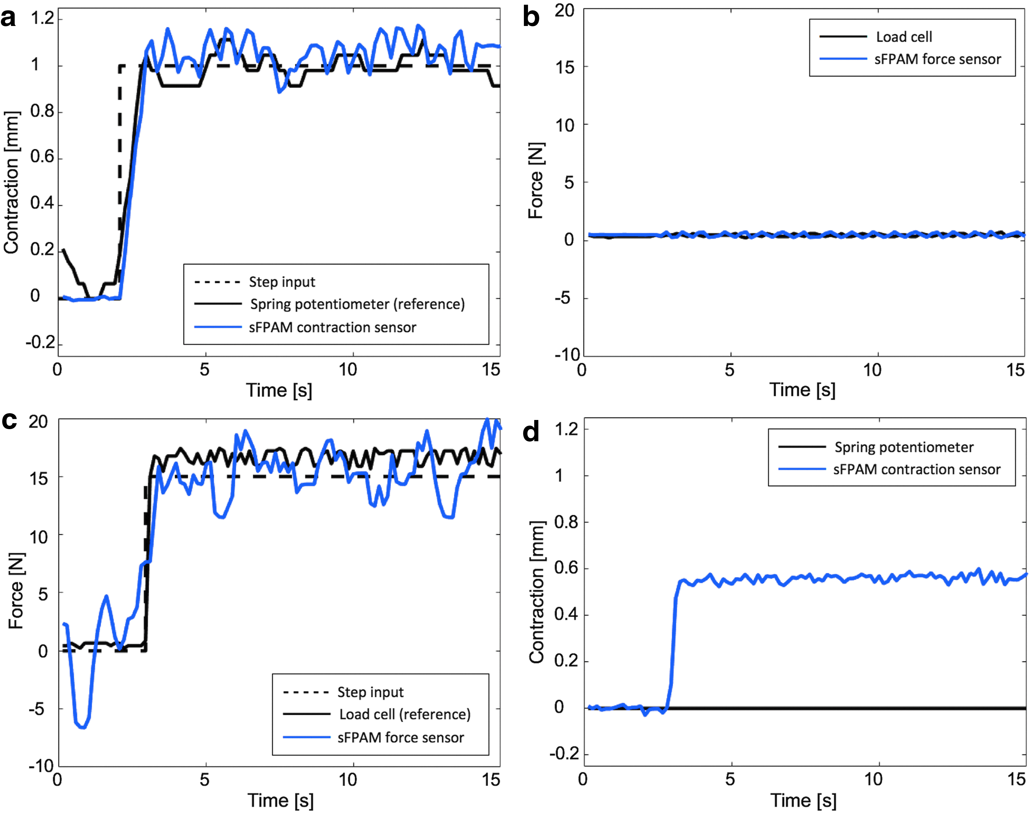
Force and position control experiments were conducted to demonstrate the feasibility of the sFPAM to reach desired set points. For position control experiments, an example of which is provided in Figure 8a and b, the actuator was able to reach desired step inputs with a rise time of 0.82 s. Meanwhile, during force control experiments, an example of which is provided in Figure 8c and d, the actuator was able to reach desired step inputs with a rise time of 0.28 s and an average error of 1.5 N. The control scheme implemented in both cases relied solely on proportional gains, which resulted in continuous oscillatory behavior around the set point.
Conclusions
Ultimately, an sFPAM capable of acting as a compact, readily deployable standalone system that can easily be incorporated into a wearable device was developed. The sFPAM, which contained embedded force and contractile sensors that mimic the behavior of organic sensors found in human muscles (namely Golgi tendon organs and muscle spindles), was experimentally characterized and demonstrated favorable agreement with the developed hyperelastic model. Additionally, the feasibility of the system to be controlled to desired force and position set points was displayed.
The usefulness and advantages of the proposed sFPAM as an integrated sensing and actuation system were further bolstered by development of an accurate, hyperelastic, analytical theoretical model. This model provides researchers and designers with a means to effectively select dimensions and materials for the sFPAM to produce forces and contractions within specific pressure ranges to successfully complete their desired tasks. In addition, due to the use of the plastic sheet, researchers can quickly iterate through sheet patterns to optimize the mechanical and electrical performance of the sFPAM. Deformation of the noninflatable terminal made of plastic sheets was not currently considered in modeling since displacement of the actuator was dominated by deformation of the elastomer layers due to the large difference in Young's moduli between the elastomer and plastic materials. However, improvement of our theoretical approximation by including deformation of plastic sheets will be one of the immediate areas of our future work.
Additional considerations should be made to further improve the performance of the overall system. Although controlled operation was successfully demonstrated, sensors should be modified to improve two key defects. First, microchannel location and layout should be optimized to minimize coupling effects of the contractile sensor. Ultimately, the contractile sensor should have minimal change in its signals during purely force-based experimentation or operation. Minimization of the coupling effect should reduce the complexity of control algorithms required for effective real-time operation of the sFPAM. Second, sensitivity of the force sensor should be improved. This can be achieved by switching to capacitive sensing, utilizing a soft polymer instead of liquid resistive sensing, optimizing the Kirigami pattern used on the laser-cut plastic sheet, or utilizing a higher resolution fabrication process for molds to create microchannels for improved resistive sensing. Furthermore, future work should focus on system identification and frequency response experiments to design and implement optimal control schemes for the sFPAM. These improvements should ensure higher fidelity in the design of position and force controllers for set point and trajectory tracking inputs with varying loads, similar to what the sFPAM would experience during real-world applications.
The next step of this research will be implementation of a set of the proposed actuators to a soft wearable robot. In such a system, the actuators with embedded proprioceptive sensing mechanisms are expected not only to provide the robotic system with the capability of individual control of each of the multiple actuators but also to facilitate their collaborations to achieve desired trajectories or to generate assistive forces. 44 Therefore, the proprioceptive information provided directly from individual actuators will help in increasing the stability and resistance to unexpected perturbations, 45 which are two critical requirements to ensure the safety of the user during control of wearable robots.
Footnotes
Acknowledgments
This work was sponsored, in part, by the GEM fellowship program; in part, by the Samsung Global Research Outreach Program (Award No.: A019487); and, in part, by the National Research Foundation of Korea (NRF) Grant funded by the Korean Government (MSIT) (Grant No.: NRF-2016R1A5A1938472).
Author Disclosure Statement
No competing or financial interests exist.