
Abstract
Abstract
This study presents the design of an underactuated, two-finger, motor-driven compliant gripper for grasping size-varied unknown objects. The gripper module consists of one main frame structure and two identical compliant fingers. The compliant finger is a monolithic compliant mechanism synthesized using a topology optimization method, and then prototyped by 3D printing using flexible filament. The input port for each finger is mounted on a moving platform driven by a gear motor, whereas the fixed port of the finger is mounted on a fixed platform. Each compliant finger can be actuated through the linear motion of the moving platform, and can deform elastically to generate the grasping motion. To demonstrate the effectiveness of the proposed design, the gripper module is mounted on a six-axis robotic arm to pick and place a variety of objects. The results show that objects with the sizes between 42 and 141 mm can be grasped by the developed soft robotic gripper. The maximum payload for the gripper is 2.1 kg. The proposed compliant gripper is a low-cost design that can be used in grasping of size-varied vulnerable objects.
Introduction
The development of a dexterous robotic gripper or hand to perform the pick-and-place task for handling of size-varied unknown objects has drawn considerable attention in developing end effectors. During task execution, the grasping fingers must be controlled via grasp synthesis algorithms to regulate the positions and forces of joints and fingertips. 1 Grasp synthesis refers to the problem of finding a grasp configuration that satisfies a set of criteria relevant to the grasping task. 2 The uncertainty of the object shape can be incorporated as a constraint into grasping planning stage, and a probabilistic model for estimation of the hand inverse kinematics can be used to investigate the corresponding hand configuration. 3
Bohg et al. 2 propose to group data-driven grasp synthesis approaches into three categories, known, familiar, and unknown objects, based on what to know a priori about the object. For the approaches dealing with unknown objects, the core part is the methodologies to extract specific features that are indicative of good grasps.
A dexterous robotic hand or gripper usually has several degrees of freedom requiring several actuators to execute the planning motion. As the control complexity, overall dimensions, and cost are increased for the design with increasing actuators, the design of underactuated mechanisms, which can minimize the usage of actuators, becomes essential. 4 A mechanism is underactuated when the number of actuators is less than the number of degree-of-freedom of the mechanism.
Dollar and Howe 5 present a compliant, single actuator hand for adaptive grasping in unstructured environments prototyped using polymer-based shape deposition manufacturing method. Odhner et al. 6 develop a compliant, underactuated hand driven by five actuators to address the need for robust manipulation. Petković et al. 7 propose an underactuated adaptive gripper made by silicone rubber to handle irregular objects with concave and convex shapes; the design of the each finger has embedded sensors, which can provide information for controlling input displacement of the gripper, and to recognize particular shapes of the objects.
The usage of soft materials to form soft robots8–11 has drawn considerable attention over the years. The materials with elastic moduli in the order of 104–109 are considered the soft materials. 11 Generally, the soft compliant hands and grippers are able to provide adaptability for handling size-varied objects.
For example, the soft anthropomorphic hand proposed by Deimel and Brock 12 uses soft silicone pneumatic actuator to provide high grasp adaptability. Manti et al. 13 present a soft three-finger gripper activated by a DC motor through a cable-driven actuation mechanism; the gripper consists of three identical silicone fingers manufactured through the molding process. Galloway et al. 14 develop soft robotic grippers that can gently conform around objects with the control input of a single hydraulic line for deep-sea collection of fragile biological specimens. Katzschmann et al. 15 develop an autonomous motion planning algorithm for a soft planar grasping manipulator 16 to perform delicate tasks with low payload.
Liu et al. 17 present an optimal design procedure (including topology and size optimization methods), which can maximize the output displacement of the synthesized compliant mechanism, to design an adaptive compliant gripper for fast grasping of unknown objects; the gripper is an underactuated two-finger design manufactured by silicone rubber. The usage of soft materials can also prevent possible damage of objects during the grasping process, which is a particularly important issue in handling of natural products for the food processing industry.18–24 Several control schemes such as constrained linear quadratic optimization algorithm25,26 and a feedforward controller based on both rigid-body and flexible modes 27 can be used in robust tracking and vibration suppression for flexible systems.
Topology optimization is a numerical method to optimize material layout within a given design domain, and is one major approach for synthesis of compliant mechanisms. The numerical algorithms of topology optimization methods are extensively investigated in the literature.28–32 Traditionally, the objective function in topology optimization is to minimize strain energy of the analysis domain; for synthesis of compliant mechanisms, the objective function in topology optimization is usually to maximize mutual potential energy, geometric advantage, or mechanical advantage.
Maximizing geometric advantage is equivalent to maximizing output displacement, whereas maximizing mechanical advantage is equivalent to maximizing output force. Mixed strain energy-based objective function has also been proposed, 33 which can consider both geometric and mechanical advantages of the analyzed compliant mechanism using adjustable control parameters.
The material distribution in the analysis domain is expected to evolve into an optimum under certain boundary conditions and constraints. Traditionally, the element update scheme in topology optimization can be classified as hard-kill and soft-kill approaches. The hard-kill method directly removes inefficient elements from the analysis domain iteratively, whereas the soft-kill method assigns a small density value for unnecessary elements to represent void element. In addition to the one-way element removal approaches, the bidirectional evolutionary structural optimization (BESO) method34–37 and sequential element rejection and admission (SERA) method38,39 allow not only to remove the inefficient elements but also to add efficient elements simultaneously.
To improve the computational efficiency for topology optimization of compliant mechanisms, the constant volume fraction method 40 and soft-add method 41 are proposed; as the target volume fraction, the ratio of target volume to total volume of the analysis domain, is usually below 30% for topology optimization of compliant mechanisms, traditional methods that remove unnecessary elements from 100% are inefficient.
Many previous studies use topology optimization methods to synthesize the optimal layout of monolithic two-finger compliant grippers.17,37–39,42–44 However, the dimensions of the gripping jaws or fingers for traditional compliant gripper designs37–39,42–44 usually ranged from 15% to 30% of the gripper length, and thus, the overall dimensions of traditional compliant grippers are usually relatively large comparing to the allowable gripping dimensions for objects.
In addition, the boundary conditions used in topology synthesis of compliant grippers usually consider only one target output port on each jaw or finger, which may not have adequate adaptability comparing with the two output port fingers. 45 Furthermore, the synthesized grippers are usually not prototyped. The one-node hinges (or de facto hinges) existed in many synthesized designs, which could result in strength problems during physical operation.
This study aims to develop an underactuated soft robotic gripper for handling of size-varied objects. A topology optimization method capable of synthesizing compliant mechanisms with multiple output ports is proposed to synthesize the compliant finger of the robotic gripper. The length of the finger is close to 50% of the gripper dimensions. The proposed topology-optimized finger design is prototyped using 3D printing, and experimental tests are performed to evaluate the gripper design. The prototype of the proposed soft robotic gripper, detailed design methodology, and experimental results are summarized in this study.
Soft Robotic Gripper
The developed underactuated soft robotic gripper in this study is given in Figure 1. Figure 1a shows the developed soft robotic gripper mounted on a six-axis industrial robot. Figure 1b and c shows the open mode and close mode, respectively, of the soft robotic gripper. The gripper module consists of one main frame structure and two identical compliant fingers. The compliant finger is a monolithic compliant mechanism that is synthesized using topology optimization method, and prototyped by 3D printing using flexible filament (thermoplastic elastomer made by BotFeeder). The input port for each compliant finger is mounted on a moving platform driven by a gear motor (Sumotor 37GARH, DC24V, 400 rpm), shown in Figures 1a and 2, whereas the fixed port of the finger is mounted on the bottom fixed platform.

Developed soft robotic gripper

Design scheme for the soft robotic gripper.
Each compliant finger can be actuated through the linear motion of the moving platform, and can deform elastically to generate the grasping motion. The initial opening between fingertips of the gripper is 175 mm at the open mode as shown in Figure 1b. The distance between fingertips at the close mode as shown in Figure 1c is 40 mm. The maximum allowable input displacement for the moving platform (from the open mode to the close mode) for the design is 50 mm. The average speed of the moving platform is measured as 6.8 mm/s, whereas the average drive speed of the gripper at fingertip is measured as 10.8 mm/s. The fingertip distance can vary with the speed up to 21.6 mm/s for the two-finger gripper.
Design Scheme
The design scheme for the proposed soft robotic gripper in Figure 1 is given in Figure 2. The gripper module consists of one main frame structure and two trapezoidal design domains of compliant fingers. The input port of the finger as defined in Figure 2 is mounted on a moving platform (with four linear bearings), which can move along four smooth rods of the main frame structure. A gear motor is used to drive the moving platform through bevel gears and threaded rod (with 1 mm pitch). The fixed port of each finger is fixed at the bottom fixed platform. When the moving platform moves downward, both fingers can deform elastically after the displacement input and generate the gripping motion.
Figure 3 shows the analysis domain and boundary conditions for topology optimization of the compliant finger. The analysis domain consists of three regions, design domain (the same as the design domain given in Fig. 2), void nondesign domain, and solid nondesign domain. The value for pseudodensity of each element in the void nondesign domain is predefined as a small positive value (0.001 in this study), whereas the value for pseudodensity of each element in the solid nondesign domain is predefined as 1. As shown in both Figures 2 and 3, the design domain for the compliant finger is a trapezoidal area. The solid nondesign domain is a rectangular area of 80 × 1 mm; the 80-mm length edge is the expected contact region of the finger.

Analysis domain and boundary conditions for topology optimization of the compliant finger.
The target design for the compliant finger includes one input port, one fixed port, and two output ports. According to findings from Petković et al., 45 the two output ports' design allows the finger to have better adaptability to accommodate irregular objects. The output port #1 is at the fingertip of the compliant finger, and the output port #2 is at the midpoint of the 80-mm length edge. An input force is applied at the input port; dummy force #1 and dummy force #2 are applied at output port #1 and output port #2, respectively. According to the dummy load method,38–42 each dummy force is a unit force applied at the desired output port in the direction of the desired displacement.
The load scheme with one input force and two dummy forces as given in Figure 3 can be decomposed into three individual load cases as provided in Figure 4; each load case can be solved individually by using the finite element method. Numerical springs are introduced at input and output ports in the optimization model to better identify the hinge-free layout in topology synthesis of compliant mechanisms.33,37–41,44,46
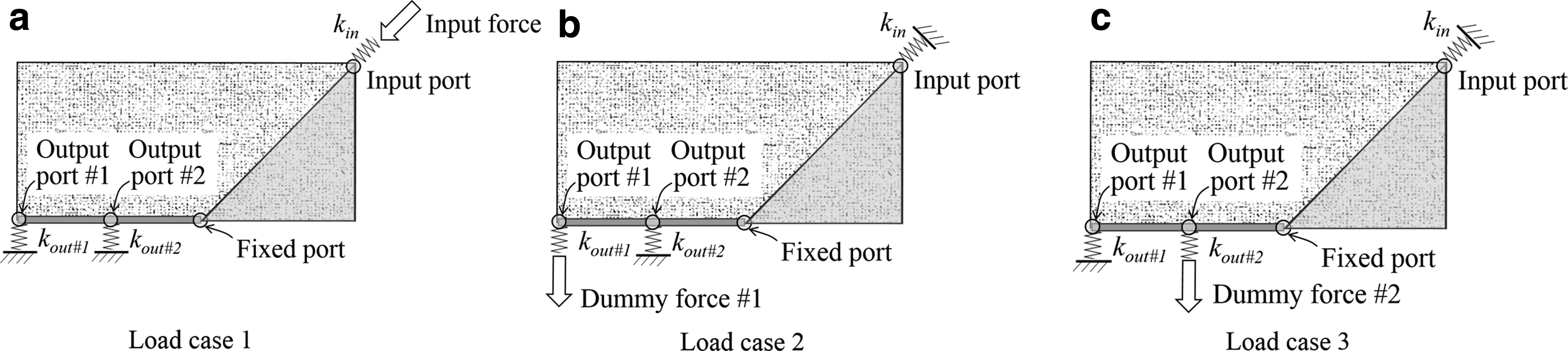
Load cases.
Formulations for Topology Optimization
One critical issue in developing the soft robotic gripper as shown in Figure 1 is the design of the compliant finger. The topology optimization method is used to synthesize the optimal layout of the compliant finger in this study (Fig. 3 shows its analysis domain). The flowchart of the topology optimization method is given in Figure 5. The procedure starts with finite element discretization of the analysis domain, and then, the finite element method is used to solve the force equilibrium problem.

Flowchart of the topology optimization procedure.
The design variable is the pseudodensity of each element, which can be varied from a small positive value to 1 by a small increment. The sensitivity number for each element can be obtained by calculating the gradient of objective function with respect to design variable. A filter scheme is utilized to minimize the possible mesh dependency and checkerboard pattern problems47–50 for the optimal topology. An averaging scheme is used to increase numerical stability. 36 An efficient soft-add update scheme 41 is applied to update sensitivity number and pseudodensity for each element. Finally, a convergence criterion is utilized to evaluate the variation of objective function values until convergence.
Based on the objective function proposed by Krishnakumar and Suresh,
33
a strain energy-based objective function for synthesis of compliant mechanisms with two output ports is proposed, which can be formulated as follows.
where c is the objective function to be maximized; η is the advantage control parameter; decreasing η increases the mechanical advantage and decreases the geometric advantage of the mechanism (and vice versa) 33 ; ζ is the output control parameter that controls the ratio of the two target output ports; Sin is input strain energy; Sout,1 and Sout,2 are output strain energy; Smut,1 and Smut,2 are mutual potential energy.
The advantage and output control parameters are weighting factors to adjust the contribution for input strain energy, output strain energy, and mutual potential energy;
The summation of the pseudodensities times the volume of each element should equal the target volume constraint. A smaller target volume leads to a mechanism with larger compliance.
The input and output strain energy are formulated as follows.
The formulations for mutual potential energy are as follows.
The global stiffness matrix
where
The elemental sensitivity number can be obtained by calculating the gradient value of the objective function c with respect to the design variable xi.
The BESO filter scheme
36
is used in this study. The first step for the filter scheme is to calculate the nodal sensitivity number αn, j by averaging the elemental sensitivity numbers of corresponding connecting elements for each node.
where i denotes element number; j denotes node number; ne is number of elements connected to the jth node.
The filtered elemental sensitivity number can be defined in terms of nodal sensitivity numbers and weight factors.
where wij is a weight factor; r is the filter radius about the center of the ith element; rij is the distance between the jth node and the center of the ith element; nr denotes number of nodes within the circle of the filter radius.
The averaging scheme
36
for the filtered elemental sensitivity numbers for every two successive iterations is used to stabilize the evolutionary results from the second iteration.
where iter is iteration number;
The soft-add update scheme given in Figure 6 is used to update the pseudodensities and sensitivity numbers. The pseudodensity for each element is initially assigned with the same value as xmin, which is a very small positive value. The calculated volume for each iteration, Viter, is defined as follows.
where vf is a predefined volume fraction constraint that represents the ratio of target volume to full volume; Ar is a predefined variation value; iter is iteration number; V0 is the full volume for the analysis domain. The calculated volume is linearly increased with the iterations until the volume fraction constraint is reached, then the calculated volume remains constant until the numerical computation is converged.

Soft-add update scheme.
A threshold value
If a filtered and averaged elemental sensitivity number obtained in Equation (8) is larger than the threshold value, the pseudodensity of the ith element (xi) is increased by one increment (Δx) in the local iteration; otherwise, the pseudodensity is decreased by one increment. In addition, a pseudodensity can be only varied from xmin to 1. The summation of the pseudodensities for all elements in the analysis domain times the volume of each element is calculated; if it is different from the previously determined volume (Viter) plus or minus a small tolerance value (tol), a new αth is calculated based on the update rules given in Figure 6 until Viter is converged.
Finally, the following convergence criterion, which evaluates the relative difference ratio for the sum of objective function values for each successive five iterations, is used to check for termination.
where c is the objective function value as given in Equation (1); n is number; err is an allowable tolerance.
Topology Optimization Design for the Compliant Finger
The topology optimization method discussed in the previous section is used to synthesize the optimal topology of the compliant finger. The algorithm is implemented in the MATLAB R2015 environment. The analysis domain in Figure 3 is meshed by 150 × 70 four-node square plane stress elements. The size of each element is 1 × 1 mm. The formulation for the stiffness matrix for each element is provided in Appendix 1. The numerical parameters include η = 0.01, ζ = 0.225, vf = 0.2, p = 3, r = 7, Ar = 0.01, x0 = 0.001, input force = 1 N, dummy force = 1 N, and numerical spring stiffness = 1010 N/mm. The material properties include elastic modulus = 11.6 MPa and Poisson's ratio = 0.45.
The pseudodensities for all elements in the design domain as in Figure 3 are initially defined as xmin. The pseudodensities for the elements at the solid nondesign domain are predefined as 1 to represent solid elements throughout the topology optimization process, whereas the elements in the void nondesign domain are predefined as xmin to represent void elements.
The topology optimization process is converged after 165 iterations. The plot for iteration number versus normalized objective function value is given in Figure 7. The y-axis of Figure 7 is the normalized objective function value calculated by Equation (1), which is nondimensional. The topology optimization results at some specific iterations (20th, 40th, 60th, 80th, 100th, 120th, 140th, and 165th) are also provided in Figure 7. It can be noticed that the topology optimization result does not change significantly after the 100th iteration. The white region denotes elements with pseudodensities equal to xmin, whereas the dark region denotes elements with pseudodensities equal to 1. The gray region denotes elements with pseudodensities between xmin and 1. The compliant finger design given in Figure 1 is based on the converged topology optimization result given in Figure 7.

Topology optimization results: normalized objective function value and optimal layouts obtained at some specific iterations (20th, 40th, 60th, 80th, 100th, 120th, 140th, and 165th). The 165th iteration layout is the converged result.
Input/Output Relationship
A 3D CAD model is built based on the topology optimized finger design obtained in Figure 7; the thickness of the finger is 20 mm. The monolithic compliant finger is then manufactured by 3D printing using thermoplastic elastomer. The infill percentage in 3D printing for the compliant finger is defined as 50%. The equivalent elastic modulus for the 50% infill 3D printing material is experimentally measured as 11.6 MPa (at the linear elastic region) through a tensile test; the experimentally obtained equivalent elastic modulus was used as the material property in the previous topology optimization process.
The experimental setup for measuring the input/output relationship of the compliant finger can be seen in Figure 8. The compliant finger is fixed at its fixed port on a fixed block on two smooth rods. The input port of the finger is fixed on a linear slide, which can move along the two rods. The compliant finger can be actuated by the displacement input specified at the input port. The output displacement is measured from the output port as denoted in Figure 8 in both x and y directions.

Experimental setup for measuring the input/output relationship of the compliant finger.
The plot for the input/output relationship of the complaint finger is given in Figure 9; the vector sum output displacement at the output port is roughly linear in 0–40 mm displacement input range. The geometric advantage (defined as the ratio of output displacement to input displacement) for the compliant finger is about 1.41 in average, which is a measure of displacement amplification. The deformed shape of the compliant finger at specific displacement input can be seen in Figure 10, which shows finger deformation at 10, 20, 30, and 40 mm displacement inputs.

Input/output displacement relationship of the compliant finger.
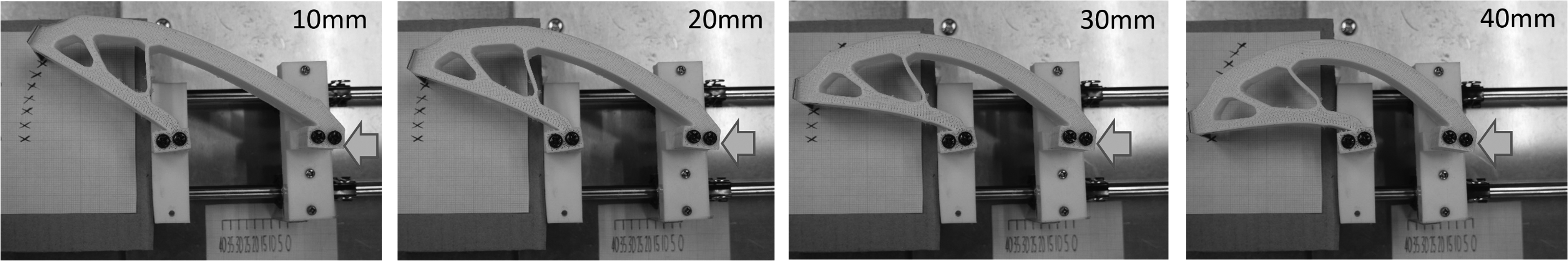
Deformation of the compliant finger at specific displacement input (10, 20, 30, and 40 mm).
The setup for measuring the input/output force relationship for the compliant finger is similar to the setup for the displacement measurement as shown in Figure 8, except that two additional force sensors are placed at the input port (Lutron FG-6100SD) and fingertip (Lutron FG-6005SD) to measure the input and output forces. The input force curve given in Figure 11 shows the test results for the relationship between input displacement and input force for a free moving finger. The required input force to actuate a single finger is roughly linearly increased with the input displacement. A force of 32 N can provide 40 mm displacement input (as shown in Fig. 11) and generate a vector sum output displacement of 56 mm (as shown in Fig. 9) for the finger.

Input force/input displacement relationship of the compliant finger, and resultant forces due to contact.
Figure 11 also shows the input and output force curves for the condition when the finger is in initial contact with a fixed object (force sensor) at an input displacement of 33 mm. The input force required and output force measured in 35–47 mm displacement input range are shown in Figure 11. The maximum input force required for the finger at this condition is 50 N, whereas the maximum output force is 13 N.
Figure 12 shows the input and output forces measured from an initial contact at some specific displacement input locations. The experiment is performed by placing the output force sensor right in contact with the fingertip, and then, the displacement inputs of 5 and 10 mm are further applied at the input port to obtain the input and output forces. The above process is performed iteratively for every 5 mm displacement input. The x-axis in Figure 12 is the input displacement required for the initial contact with the output force sensor, whereas y-axis is the force measured from either input or output force sensor. For example, when input displacement is 10 mm, the compliant finger is deformed, and then, the output force sensor is placed (and fixed) right in contact with the fingertip. Then, a displacement input of 5 mm is further applied at the input port, and the input and output forces are obtained as 30 and 14 N, respectively, at the +5 mm measurement condition as shown in Figure 12. For the +10 mm measurement condition when the initial contact is at the displacement input of 10 mm, the input and output forces are increased to 50 and 26 N, respectively. In this test, the maximum input force required is 54 N at the +10 mm measurement condition, when the initial contact is at the displacement input of 0 (the beginning of actuation).

Input and output contact forces at specific displacement input.
Finite Element Analysis
To analyze the dynamics and contact behavior of the compliant finger, a 3D finite element model as given in Figure 13 is developed to investigate the maximum stresses on finger and object, and the resultant force calculated at the fixed object due to the contact with the compliant finger. The general purpose finite element program, LS-DYNA, is used to analyze the dynamic problem. Both the finger and the semispherical object are meshed by hexagonal elements (with a total element number of 48,640 and 28,000, respectively). The fixed port of the finger is fixed in the simulation, whereas the input port of the finger is moved in −y direction with a speed of 100 mm/s. The semispherical object is fixed at its right surface.

Finite element analysis model and results. Color images available online at www.liebertpub.com/soro
Three analysis cases are performed to investigate the effect of object elastic modulus on the generated stresses and forces. The values for the elastic modulus of the object are defined as 1 MPa, 11.6 MPa (the same value as the compliant finger), and 100 MPa, respectively, for the three analysis cases. Figure 13 shows the deformed shapes and equivalent stress contours (for the object elastic modulus = 11.6 MPa case) when the displacement inputs are 33 mm (initial contact) and 50 mm (maximum allowable displacement input). The maximum equivalent stresses of the finger are 1.4 and 3.0 MPa, respectively, for the 33 and 50 mm input conditions. The failure stress of the finger material is 11.2 MPa.
Figure 14 shows the maximum equivalent stresses of the finger at different displacement inputs. It can be noticed that the finger stress curves for the three different object elastic modulus cases are almost the same. The material of object does not change the finger stress in these three analysis cases. Figure 15 shows the maximum equivalent stresses of the object at different displacement inputs. The results show that the softer object (with lower elastic modulus) has lower maximum stress. Figure 16 shows the simulated resultant forces on the fixed object. The results show the resultant forces are almost the same for these three cases. In addition, the simulated results agree with the experimental measured force curve as discussed in Figure 11 (output force with initial contact at 33 mm curve), which is also given as the experimental result in Figure 16.
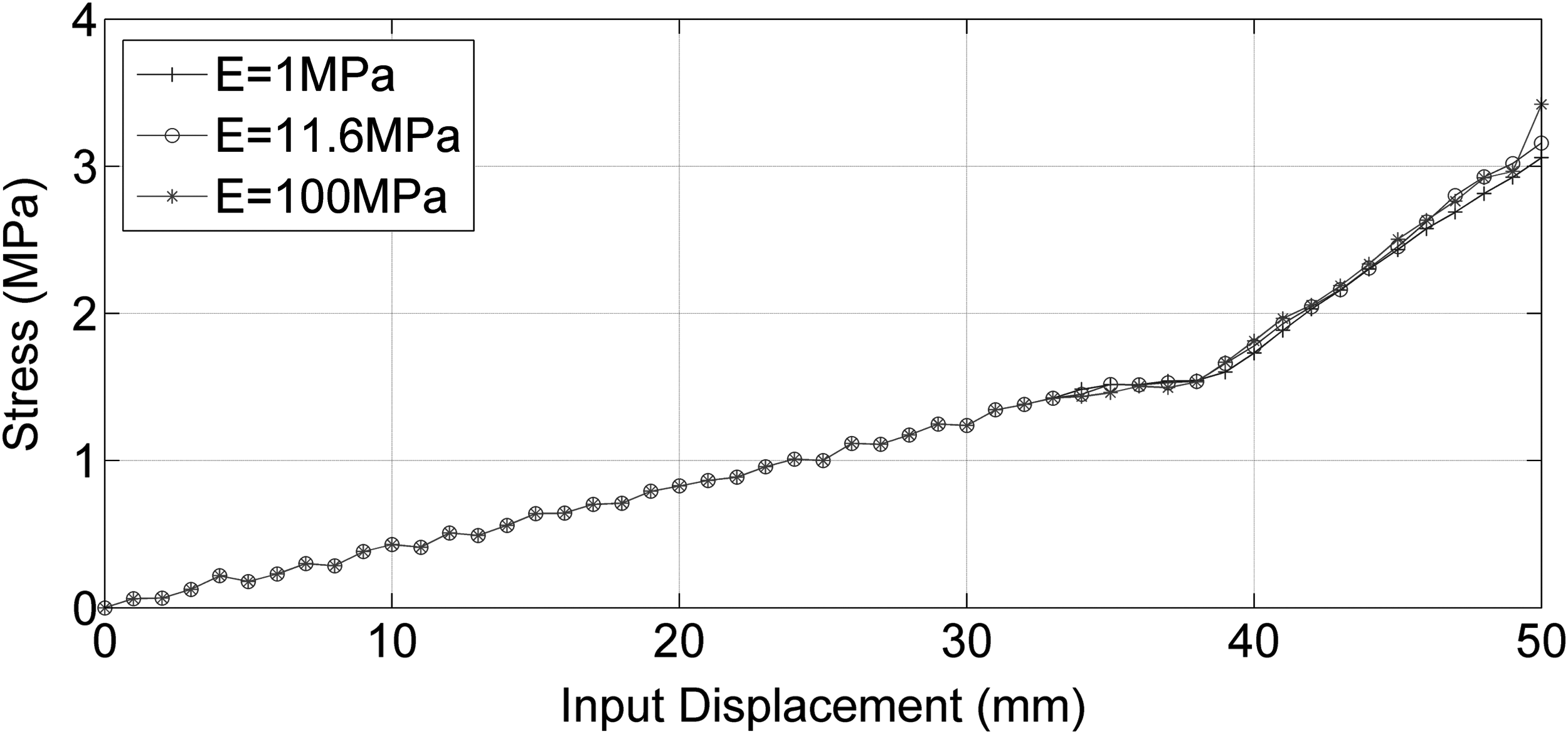
Maximum finger stress for objects with different elastic moduli.
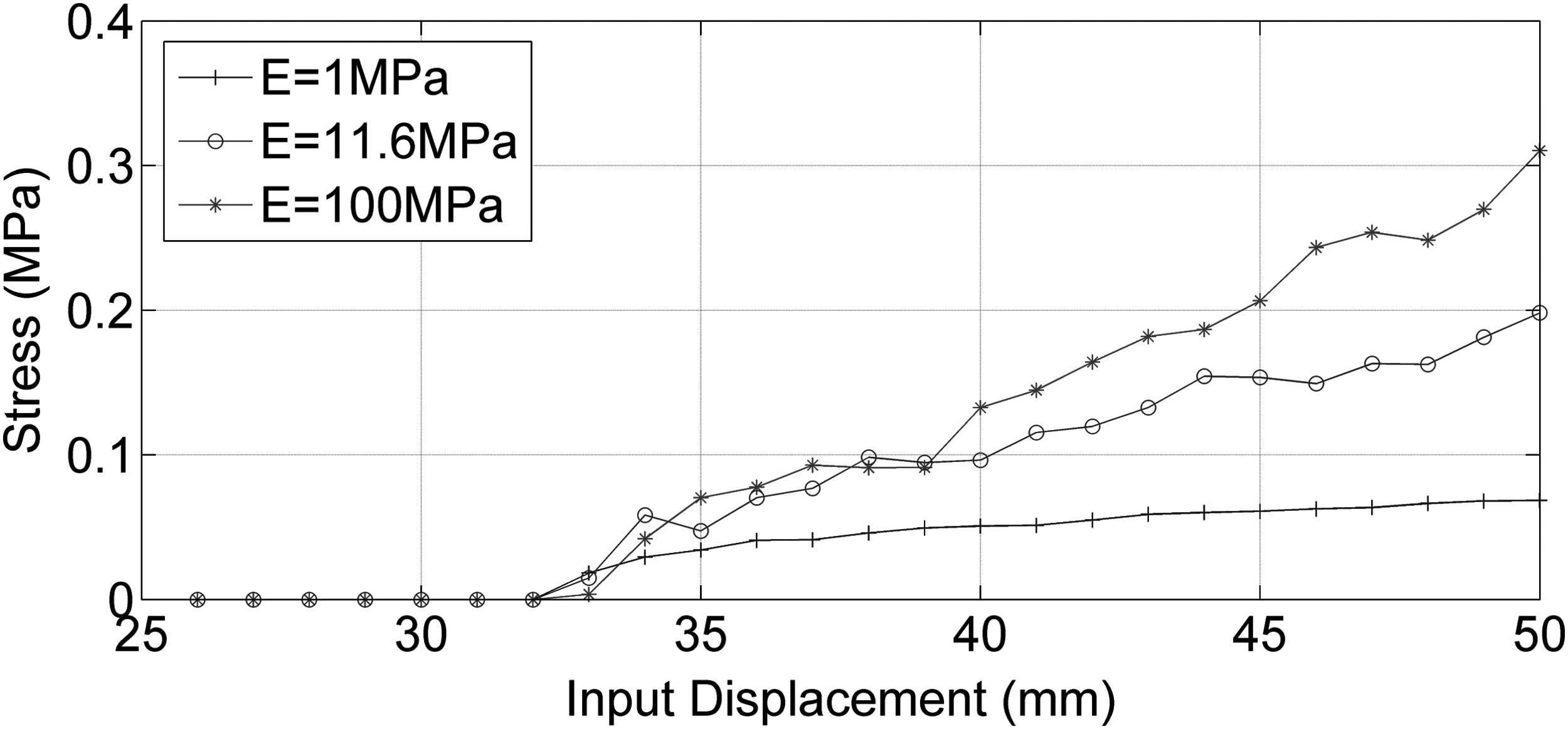
Maximum object stress for objects with different elastic moduli.
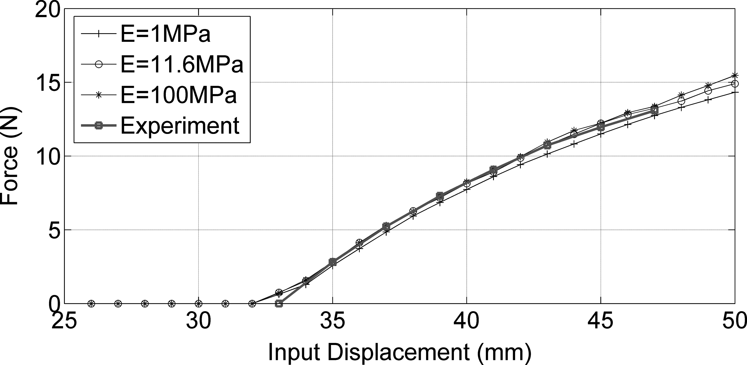
Resultant force for object with different elastic moduli and experimental results.
Grasping Test
The topology-optimized finger design in Figures 7 and 8 is used in design of the two-finger underactuated gripper given in Figure 1. A payload test as shown in Figure 17 is performed to evaluate the maximum allowable weight of object that can be carried by the soft robotic gripper. The experiment is performed iteratively by gradually increasing the number of mass blocks in the tray. Figure 18 shows the experimental results for the maximum allowable object weights at different displacement inputs. The 35–50 mm displacement input range is the general effective range for the gripper for a stable grasping. It can be noticed that a larger displacement input leads to larger payload. The maximum payload for the gripper is identified as 2.1 kg (as the condition shown in Fig. 17) when the displacement input is 50 mm (which is the maximum allowable input displacement for the design).

Payload test (the maximum payload is 2.1 kg with displacement input of 50 mm).

Input displacement and maximum payload relationship.
It should be noticed that the measured payload can be affected by the friction between the gripper and targeted object. The estimated maximum payload may vary according to the surface condition of the objects being handled.
A grasping test to evaluate the size range for an object that can be grasped by the proposed soft gripper is also carried out. Figure 19 shows the items used in the grasping test, which include box, tissue, bottle water, can, larger box, plush toy, apple, magic cube, tape, and hard disk drive. The object size at the gripped location, the weight of object, and the required input displacement at the input port are summarized in Table 1. The minimum and maximum allowable object sizes that can be grasped by the soft gripper are 42 and 141 mm, respectively.
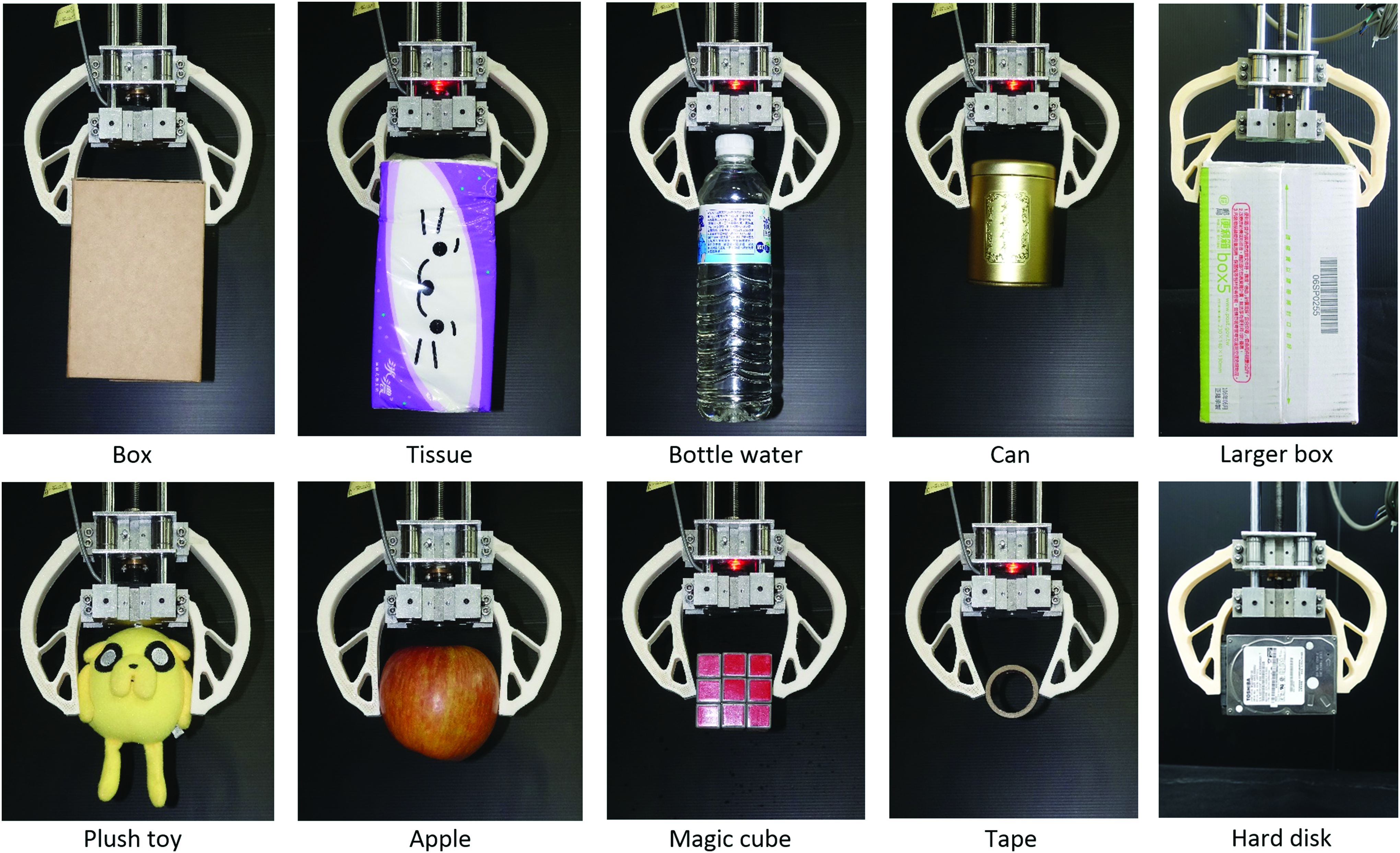
Sample items grasped by the developed soft robotic gripper. Color images available online at www.liebertpub.com/soro
Objects Grasped by the Soft Robotic Gripper
To demonstrate the capability of the gripper to handle vulnerable objects, balloon and water balloon are used as the targets to be grasped by the developed gripper. The results are given in Figure 20, which shows the grasping results at several different input displacement conditions. The experimental results given in Figures 19 and 20 show that the developed soft robotic gripper can be used to pick and place a variety of objects from soft and deformable balloon to relatively rigid hard disk drive without causing damages. The soft compliant fingers can deform to accommodate objects, which can increase contact region between gripper and object to generate a stable grip as well as to minimize the contact stress on object.

Grasping vulnerable and deformable objects (balloon and water balloon) by the developed soft robotic gripper. Color images available online at www.liebertpub.com/soro
Conclusion
In this study, an energy-based objective function incorporated with the soft-add scheme for topology synthesis of compliant mechanisms with two output ports is developed to design an innovative soft robotic gripper. The proposed gripper is a two-finger underactuated design; each finger is synthesized by using the proposed topology optimization method and prototyped by 3D printing using thermoplastic elastomer. The flexible finger is a compliant mechanism that can be operated via elastic deformation. In addition, the compliance of the finger can prevent possible damages for the objects being handled during the grasping process.
Unlike traditional monolithic two-finger compliant grippers, this study proposed a rigid/flexible integrated gripper module, which uses a motor-driven linear moving platform to drive two individual compliant fingers mounted on a fixed platform. The existence of the fixed platform also allows the design to account for objects with larger size without increasing finger dimensions. In addition, the length of the finger is close to 50% of the gripper dimensions, which is around 50% larger than traditional designs. The test results show that the proposed soft robotic gripper can be used to grasp unknown objects with sizes between 42 and 141 mm.
The average closing speed of the gripper measured at fingertip is 10.8 mm/s. The dimension of finger opening distance can vary with the speed up to 21.6 mm/s for the two-finger gripper. The current design can be used for applications where the requirements on the response speed are less than the closing speed. The maximum estimated payload for the gripper is 2.1 kg, which may vary according to the friction between gripper and objects. The proposed gripper is expected to be further improved by reducing the overall dimensions, and increasing the payload as well as drive speed of the compliant fingers. The effects of filament type and infill percentage of the 3D-printed material on the gripper performance can also be further investigated.
Footnotes
Acknowledgment
This work was supported by grants, MOST 105-2221-E-006-082 and MOST 106-2218-E-006-017, from the Ministry of Science and Technology of Taiwan.
Author Disclosure Statement
No competing financial interests exist.
Stiffness Matrix for Square Plane Stress Element
The stiffness matrix (
where E is elastic modulus;