
Abstract
Abstract
Soft robot arms possess unique capabilities when it comes to adaptability, flexibility, and dexterity. In addition, soft systems that are pneumatically actuated can claim high power-to-weight ratio. One of the main drawbacks of pneumatically actuated soft arms is that their stiffness cannot be varied independently from their end-effector position in space. The novel robot arm physical design presented in this article successfully decouples its end-effector positioning from its stiffness. An experimental characterization of this ability is coupled with a mathematical analysis. The arm combines the light weight, high payload to weight ratio and robustness of pneumatic actuation with the adaptability and versatility of variable stiffness. Light weight is a vital component of the inherent safety approach to physical human-robot interaction. To characterize the arm, a neural network analysis of the curvature of the arm for different input pressures is performed. The curvature-pressure relationship is also characterized experimentally.
Introduction
A
Soft robots owe these characteristics to the intrinsic compliance of their physical structure. In the context of soft robot arms, compliance allows passive adaptation to external objects' shape and a much higher degree of flexibility than rigid arms. Soft-bodied arms are also advantageous because they are usually made of low cost materials. Another characteristic that soft robot arms can possess and is vital for physical human-robot cooperation is light weight. This is one of the main requirements for the safety of the human user in case of collision, especially in constrained impacts, 2 where the user is sitting in a chair, for example.
A lightweight design ensures an element of inherent safety, 3 namely the safety is included in the physical structure of the device reducing the threat for the user. Because of these reasons, low weight is often a feature in the design of robot arms aimed at physical human-robot interaction, examples include the rigid-linked LWR III robot arm 4 and BioRob Arm. 5 Examples of reduced-weight soft robot arms are the OctArm 6 and Festo's Bionic Handling Assistant (BHA), 7 hyper-redundant continuum robots. Despite the light weight and versatility of these structures, they are limited by the inaccuracy in positioning and orienting their end-effectors. This can be helped by introducing variable stiffness.
Under a given load, a variable stiffness structure will deform proportionally to its stiffness. A variable stiffness robot can be stiff for precise positioning tasks with high loads and it can be compliant when the task requires it, for example for safe human-robot interactions. Variable stiffness is at the core of many successful robot arm designs. 8 In some cases, the variable stiffness is active, created mainly through a control scheme, as in the LWR III robot, 9 and in other cases, it is built in the rigid mechanical structure, 10 for example, utilizing variable stiffness actuators.11,12 These actuators allow the apparent output stiffness to be changed independent of the output position. They can provide energy efficiency and high velocities, but are hampered by their elevated size and weight.
An example of a technique that allows obtaining variable compliance in a soft robot structure is the material jamming working mechanism.13,14 Material jamming has indeed been utilized in continuum manipulators to achieve variable stiffness.15,16 Variable stiffness can also be achieved by exploiting the ability of water-filled pockets to increase their rigidity once under pressure. 17 Also, pneumatic muscle actuators (pMAs) have been filled with high bulk modulus fluids like water to increase their stiffness. Hydraulic pMAs are reported in Tiwari et al. 18 and Shan et al. 19 High bulk modulus fluids have the disadvantage of increasing the weight of the structure considerably, a considerable problem unless they are used in underwater robots. 20
The novel robot arm physical design presented in this work combines the light weight, high power-to-weight ratio, and robustness of pMAs, with the adaptability and versatility of variable stiffness. In the OctArm, BHA, and similar devices, the structure's stiffness is linked to its length. Differently from previous devices, the novel design presented in this article combines contractile and expanding muscles so that it is possible to change positioning and stiffness of the arm independently.
One of the main issues with pMAs is the complexity and nonlinearity of their behavior. The most used static model is the one by Chou and Hannaford 21 where the principle of virtual work is utilized to link force output and internal pressure. To further improve the accuracy of description of pMA behavior, other models are proposed in the literature. For example, by considering stress effects in Davis et al., 22 the precision of force prediction is increased, and by integrating the effect of the tip portions, a more accurate description of the pressurized shape of the pMA is given in Tondu. 23 Complex modeling of the static friction and its effect on hysteresis are the main foci of research in Schulte, 24 Davis and Caldwell, 25 and Vo-Minh et al. 26 The aforementioned issues in modeling the behavior of pMAs apply to all soft-bodied structures and transfer to difficulties in their control as reported in Trivedi et al. 27 To tackle this challenge, solutions involving neural networks (NN) are introduced in the literature. 28 These solutions inspired our modeling approach.
In Soft Arm Description of this work, the new physical structure of the arm is introduced. In Decoupling Length and Stiffness Testing, the case for novelty of the arm is made by showing the independence of arm length and stiffness and by comparing its stiffness with the stiffness of an arm link made of only one type of pMAs, similar to other arms in the literature. This section also provides the first part of the characterization effort on our link by focusing on analyzing the relationship between actuator pressures and stiffness. The novel link characterization is continued in Analysis and Testing of Curvature that focuses on the relationship between actuator pressures and curvature. This is important as the arm curvature or bending is its normal operational movement in space. First, both a mathematical and an NN analysis of curvature are proposed. Second, the variation in curvature of the arm for different payload magnitudes is tested experimentally. General discussion and conclusions relating to this study are formulated in General Discussion and Conclusions and Future Work.
Soft Arm Description
The novel device is a continuum pMA arm (Fig. 1). This arm comprises one link and hence allows bending in one direction at a time.

The novel robot arm. The contractile actuators are in black and the central extensor is in gray. pMA, pneumatic muscle actuator. Color images available online at www.liebertpub.com/soro
Design concept
A pMA is a two-layered system consisting of an inner elastomeric bladder surrounded by an external woven braided shell. In pMAs, θ is the wind angle, which is the angle of the pMA braid with respect to a line along the center of the actuator. The wind angle of the braided shell when the internal pressure is zero is of critical importance since in case θ >54°44′, the pMA is an expanding muscle, and if θ <54°44′, the pMA is a contractor muscle.6,29
The novel physical design presented in this article allows varying stiffness and end-effector position independently, by using both contractile and expanding muscles. This specific structure also permits an increase of the bending angle compared to an arm made purely of contractile muscles. The arm is made of a parallel array of six contractile pneumatic muscles and one central extensor muscle, as shown in Figure 2. As a result, the structure length along the neutral axis is an average of the length of the two muscles types. The length along the neutral axis varies with muscle pressure, but the neutral axis is always coincident with the center of the extensor muscle.

pMA actuations to vary stiffness. In solid color: inflated pMAs; in polka dot pattern: noninflated pMA. Configuration
The relationship between stiffness and internal pressure in pMAs can be approximated to a linear one 21 and the same holds true for a structure built entirely of pMAs like ours. Tailoring the amount of inflation of the two muscle groups, a series of configurations of different stiffness can be obtained for the same length. For example, the same arm length can be obtained (1) in a low stiffness configuration by inflating the expanding muscle and the internal parallel array of contractors and keeping the external array of contractors deflated and (2) in a high stiffness configuration by increasing the internal pressure of the expanding muscle and inflating all contractile muscles with the same pressure (Fig. 2). Furthermore, different stiffness configurations can be obtained for the range of curvatures obtainable with the arm. To achieve this, the pressure of both types of muscles needs to be adjusted.
The maximization of the produced force and payload is the main reason that influenced the number and placement of contractor actuators. Extensor actuators allow robot arms to reach higher curvatures, while contractile actuators grant a higher force. The force produced by each single muscle can be calculated with the virtual work method from Chou and Hannaford
21
as follows:
where P is the pressure in the actuator in Pascal (Pa) and Do is the theoretical maximum diameter. Typically, pneumatic muscles are used in an unbent configuration and the braid angle is therefore equal around the circumference of the muscle. However, when a muscle is bent, the braid angle on the inside of the bend will increase and the braid angle on the outside of the bend will decrease. The braid angle along the center of the muscle (neutral axis) will remain unchanged and this is the angle that will be considered in the following analysis.
Based on Equation (1), a muscle will generate different forces depending on whether it is an extensor or contractor muscle. For example, an extensor muscle with P of 100 kPa and Do of 0.07 will produce a maximum force of 247N; however, if the same material is used to form a contractor muscle, its maximum force would be 629N. In the actuators of our link, Do has been obtained experimentally and is 80 mm for the extensor and 35 mm for the contractile muscle. The resultant maximum extensor muscle force is 233N and the maximum contractor muscle force is 159N. The calculations behind these numbers are shown in the Supplementary Data (Supplementary Data are available online at www.liebertpub.com/soro).
Description of the physical structure
The arm comprises seven in-house developed pneumatic actuators inspired by the work described in Davis et al. 22 The arm is made up of a central extensor and a parallel array of six contractors (small cylinders in Fig. 3). The contractile muscles are divided into two groups, an internal (checkerboard pattern in Fig. 3) and an external one (wavy pattern in Fig. 3), each composed of three muscles. The internal group is close to the extensor muscle (large cylinder in Fig. 3), which sits at the center of the arm. The three internal muscles are equidistant from the center of the arm (35 mm away) and are placed at 120 degrees from each other. The external group is placed 65 mm away from the center of the arm and the three muscles are at 120 degrees from each other and in line with the three internal muscles. An internal contractile muscle and an external contractile muscle in line with each other create a pair. The inflation of a pair of contractile muscles shortens them, causing the arm to bend around the inflated pair. Simultaneously inflating two pairs with equal pressure will have the robot arm bend at equal distance from both pairs. By dosing the amount of input pressure to each muscle pair, it is possible to bend the link in all directions. All the actuators are secured to 150 mm diameter mounting plates at both ends of the arm.

Schematics of the arm. In checkerboard pattern: internal parallel array of contractile muscles, in wavy pattern: external parallel array of contractile muscles. Color images available online at www.liebertpub.com/soro
To ensure contractile actuators are always in contact with the extensor actuator, irrespective of the curvature of the element, ties (shown as small circular objects in Fig. 3) are utilized. These are made from flexible nylon cables that are fed through two adjacent openings in the braid material. These ties secure each actuator of the external group to the adjacent actuator of the internal group. In turn, the actuators of the internal group are secured by these ties to the central extensor actuator.
Similar ties are used to secure a nylon wire along the full length of the outer side of each external contractile actuator (Fig. 3). These wires are wound around pulleys mounted to three encoders on top of the link (Fig. 1) so that the amount of contraction of the external actuators can be measured. This measurement is an indication of the bending angle of the arm, which increases proportionally to the pressure input in the muscle. The pressurized air can be fed to each muscle separately, so that they can be controlled independently. The manipulator's length when all muscles are deflated is 380 mm. Its maximum length, achieved when the expanding actuator is pressurized with 500 kPa, is 447 mm. The manipulator's minimum length, 357 mm, is achieved when all 6 contractile muscles are at 500 kPa.
The weight of the arm is 1.12 kg, which is comparable to the BHA (1.8 kg) and less than the OctArm (∼6.9 kg). The maximum number of active degrees of freedom (DoF) of our arm is four compared to the OctArm (9 DoF) and BHA (11 DoF). The BHA is made of polyamide, a material with higher rigidity compared to the pMA materials the OctArm and our arm consists of silicone rubber and a nylon braid shell. The resultant light weight and compliance of these structures give them inherent safety. The compliance, however, also results in the loss of accurate positioning. Hence, the robot arm described in this article is comparable to other soft and pneumatically actuated arms, but its ability to vary stiffness and end-effector position independently sets it apart from them. This ability is analyzed in the following section.
Decoupling Length and Stiffness Testing
The decoupling of length and stiffness means that either the stiffness of the link can be changed while the link length remains constant or the link length can be changed while the stiffness remain constant. Both instances are tested experimentally in the following section. Beforehand, a mathematical analysis underlining these capabilities is given to characterize the arm.
Mathematical analysis
The diagram in Figure 4 shows a planar variable stiffness continuum manipulator link consisting of a central expansor muscle and two contractile muscles on either side. In our link, there are actually three groups of contractile muscles, but to simplify, we consider only two contractile actuators (identified as Mathematical Analysis and Constant Length, Varying Stiffness). The forces exerted by both contractile and extensor muscles are shown in both configurations (Fig. 4(α) and (β)); however, configuration (β) also shows an additional external load applied to the link arm, identified by the symbol F. Hence, the manipulator configuration shown in Figure 4(α) is defined as unloaded, and the configuration shown in Figure 4(β) is identified as loaded.
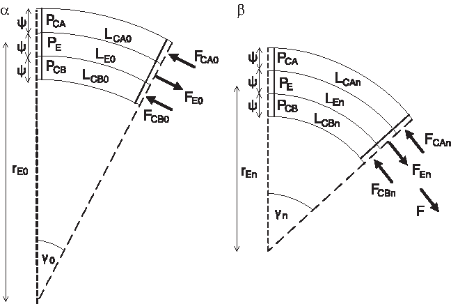
Unloaded configuration of the link (α) and loaded configuration of the link (β). The “0” suffix identifies the unloaded configuration, the “n” suffix identifies the loaded configuration. “F” is used to identify force, “P” is utilized for pressures, “L” for muscle length, “r” for the radius of the link arm, “γ” for the angle of the link arm bending, and “ψ” for diameter of the contractor muscle end cap.
Unloaded manipulator
In Figure 4(α), the manipulator is in a static, no load configuration and its length L can be described by Equations (2–4):
where r is radius of the structure (Fig. 4), γ0 is the angular displacement between the two ends of the structure, and ɛ is used in this analysis as a general expression for an increment. The subscript “0” is used to identify variables in their unloaded state. The length L of an actuator can also be expressed as follows:
where b is the length of one strand of material used to form the muscle braid, which spirals around the circumference of the muscle n times along its length. We assume each strand to be inextensible. In the unloaded position, all muscles are producing forces, the contractors are attempting to shorten the manipulator, and the extensor muscle is trying to elongate it. The force generated by the contractors (FCA and FCB) is equal and opposite to the force produced by the extensor (FE); hence the end of the manipulator remains stationary.
The force generated by a pneumatic actuator is given by Schulte's force Equation (1), where Do is the theoretical maximum muscle diameter at θ = 90°.
where n is the number of times each strand circles the muscle. The equations can be combined to give an equation for muscle force (F) with respect to muscle length:
where P is the pressure in the muscle.
Therefore, the forces being generated by the three muscles when at the target position defined by
where LCA0, LCB0, and LE0 are the lengths of the three muscles required to reach the target position defined by
There are potentially infinite combinations of pressures that will lead to the same target position. Higher values of PE will require PCA and PCB to be raised to generate more force and satisfy Equation (6). It is therefore possible to achieve the same end position with both a combination of low pressures and a combination of considerably higher pressures. It is proposed that this ability to vary the total amount of pneumatic pressure in the system, while still being able to achieve the same target position, will allow the stiffness of the system to be varied independently of position. The remainder of this analysis will seek to prove this mathematically.
Loaded manipulator
An external force F is applied to the manipulator (Fig. 4 (β)). This external force will result in a change in length of the three muscles and therefore a change in the curvature of the manipulator. The following analysis will assume the applied force does not create any torque on the free end of the manipulator. The subscript “n” is used to identify variables in their loaded state.
The lengths of the manipulator would change as follows:
The forces acting on the end of the manipulator will now be as follows:
If we assume the pressure in all the muscles remains unchanged from the unloaded configuration, when an external force is applied the end of the manipulator will move and each of the muscles will experience a change in length (either extension or contraction). As a muscle's force is a function of its length, the force each muscle is applying to the end plate will be different in the loaded configuration from the unloaded configuration. We can define this change in muscle force as follows:
This equation can be used to create an expression for the difference in force that each muscle generates when its length is changed from Lo to Ln due to the application of the load.
Similarly,
These are the amounts of external force to be applied to each muscle to achieve the deflection shown in the loaded case. It can be seen that the amount of force that needs to be applied to each muscle is proportional to the pressure in that muscle.
Consider, first, the manipulator in a low pressure operating mode where a low value of PE has been chosen. As muscle force is proportional to pressure, this means FEO will be low and so the equal and opposite forces FCA0 and FCB0 will need to be low; hence the pressures PCA and PCB will also be low. If the pressure in the muscles remains unchanged and a force is then applied to the manipulator, it will move from position
As
If we now consider the manipulator at the initial position
In both scenarios, the manipulator has been deflected by the same amount δ; however, it has been seen that in the higher pressure mode, the force needed to move the manipulator is greater than in the lower pressure operating mode. As stiffness is defined as force/displacement, it therefore follows that the stiffness of the system becomes higher when the total pressure in the system is increased.
Constant length and varying stiffness
This experiment tests whether changing the pressure of both the extensor and contractile muscles in the link allows achieving the same link length with different stiffness magnitudes. It is important to point out that the change of the link length would not change the position of the neutral axis and the muscles are filled with pressurized air at ambient temperature (∼20°C).
The experiment is divided into two phases. The first phase involves setting a series of different extensor muscle pressures, which, together with adequately selected values of contractile muscle pressures, would keep the link length constant. The link structural stiffness magnitude of each one of these configurations is tested in the second phase of the experiment. Both phases are repeated utilizing, in one case, only the internal parallel array of contractile muscles and, in the second case, both the internal and the external parallel array.
In the experiment, three expansor actuator pressures, 50 kPa, 150 kPa, and 250 kPa, are utilized. Each expanding actuator value translates into a different experiment, where the length of the link is brought to 360 mm by pressurizing the contractile muscles. In the first case considered, when only an internal contractile actuator is used, an expanding actuator pressure of 50 kPa requires the contractile muscles to be pressurized with 250 kPa to reach the target 360 mm length. When the expanding muscle pressure is raised to 150 kPa, the pressure in the contractile muscles is 400 kPa, and once the expanding pressure is increased to 250 kPa, the pressure in the three contractile muscles is raised to 500 kPa. In the case where both internal and external contractile actuators parallel arrays are used and pressure in the expanding actuator changes from 50 kPa to 150 kPa and 250 kPa, a 360 mm link length is obtained by pressurizing the contractors by, respectively, 200 kPa, 270 kPa, and 290 kPa. As can be observed, higher pressures in the contractile actuators are required in the three muscle case compared to the six actuators case to achieve the same arm length. This is because the same contractile force is spread among three actuators instead of six; hence each actuator needs to generate a greater force. The pressure values are set up manually relying on the precision gauges provided with the air compressors. These gauges possess an accuracy of 10 kPa. Thirty seconds are waited to allow the measured value to settle before a further pressure adjustment is made.
Experimental setup
The link is fixed to the testing table and the safety structure around the link, shown in Figure 5, is also fixed to the table to provide a reference frame. A set of weights of increasing magnitude are hung from a cable that is attached by a pulley to the end of the robot link to cause a displacement of the end effector. The set of weights spans from 0.5 to 5 kg, with an increment of 0.5 kg. This is to test the stiffness of the arm. Stiffness is inversely proportional to displacement. Namely, if the same weight is hung at the end effector of a compliant and a stiff arm, in the first case the displacement would be higher than in the second case. A laser pointer is fixed to the end effector pointing toward a graph paper sheet fixed on the right side of the safety structure. This allows the position of the end effector to be recorded. During the experiment, the position of the end effector and hence its displacement vary both along the Y and Z axis. The displacement along the Y and Z axis is measured. As the link bends, the cable that applies force to the base plate will cease to be perpendicular to the plate. This means that only a component of the force will be acting perpendicular to the base plate. To overcome this, the height of the pulley is raised as each load increment is applied to attempt to ensure that the force is always applied perpendicularly, irrespective of the plate's orientation.

Variable stiffness test rig.
Results
Changes in the displacement of the end-effector position against the force applied at the end-effector are shown in Figure 6. The ratio of displacement over applied force shown in the graphs is compliance, the inverse of stiffness. As it can be seen, even though the length of the link is kept constant throughout the experiments, the compliance, and hence the stiffness of the link, varies considerably (Table 1). The stiffness values are reported in Table 1. The stiffness of the overall manipulator structure is obtained by using the best linear equation fit for each set of data. This is the best linear approximation of a sometimes nonlinear set of data. The nonlinearity could derive from errors in accuracy, given by the inherent compliance of the system, and by errors in the measuring system. However, R2 is between 0.99 and 0.96, identifying a good fit of the data. The results show that the manipulator is stiffer along the Z axis than it is along the Y axis.

Arm pressure-stiffness relationship in our contractile-extensor link. Obtained as end-effector displacement as a pulling force at the end-effector is applied. In graphs
The results illustrated in Table 1 show that using this link, six different stiffness configurations can be obtained, while keeping the length constant. The comparison between the case where only the internal contractile parallel array is used and the case where both the internal and external parallel arrays are used shows that the latter setup can obtain much higher stiffness compared to the first and is hence preferable. Specifically, the percentage increase in stiffness along the Y axis (Ky) between the case in which the internal contractile parallel arrays is used with an expansor pressure of 50 kPa and the case in which both the internal and external contractile parallel arrays are utilized, and the expansor pressure is 250 kPa, is 196%. Comparing the same two setups relative to the percentage stiffness increases along the Z axis (Kz) yields a result of 195%.
Every data point in Figure 6 is the average value of five measurements. Testing is time intensive, but obtained data suggest a very small standard deviation.
Comparison with a contractile-only arm
To provide a stiffness baseline to compare with the stiffness of the novel contractor-extensor link, a pneumatic continuum arm made purely of contractile pMAs is developed. The contractile-only arm is built in-house with the same procedure, materials and dimensions of the contractile pMAs of the novel link. The contractile-only link comprises three contractile actuators. The comparison of the novel arm design with the three contractile actuator arm is important since many of the pMA arms in the literature are conceptually similar to the latter, for example the Clemson University arm, described in Bartow et al. 30 Hence, the result of this comparison provides a baseline that can be generalized to multiple existing platforms.
The contractile-only arm's stiffness is measured with the same setup that is employed to measure the stiffness of the contractile-extensor link, for ease of comparison. The length of the arm is again set at 360 mm. To reach this end-effector position, the three actuators have been pressurized with 180 kPa.
The results of the test are illustrated in Figure 7. Ky of the arm is 0.16 N/mm and Kz is 0.3 N/mm. The comparison of these stiffness values with those of the novel contractile-expanding link shows that the latter is able to achieve considerably stiffer configurations. In addition, the contractile-expanding link possesses the ability to vary its stiffness and keeping the same length, while in the purely contractile arm, stiffness and arm length are inevitably linked. The use of both contractile and expanding actuators in the same structure also allows increased bending angle compared to an arm made purely of contractile muscles. The work described in the following section aims at characterizing the bending angle, or curvature of the arm.

Arm pressure-stiffness in the contractile-only link. Displacement of the end-effector of the contractile-only link as a pulling force is applied at its end-effector. To reach the same arm length of 360 mm as in Figure 6 experiments, the contractile-only actuators have been pressurized with 180 kPa. The contractile-only link has a higher compliance than our contractile-extensor link shown in Figure 6.
Decoupling of position and stiffness while bending
It is has been shown above that once the pressure in the extensor muscle is increased, to go back to the initial end-effector position, the pressure in the contractor muscles must be raised. It has also been shown that a higher total pressure in the system results in a stiffer configuration. However, to this point, this has only been demonstrated for a straight link. To show that the same principle applies when the link is flexed, an initial target position of the end-effector at 370 mm below the link's base plate and 140 mm horizontally from its central axis is defined, that is, the link is forming a curve. The extensor muscle is then pressurized to the required test pressure and then, the pressures in the contractor muscles are manually adjusted so that the end-effector of the link moves to the target position. To reach the target position, a higher pressure is required in the contractor muscle when the pressure in the extensor muscle is raised, as it is in the straight link experiments. The flexed arm experiment is repeated at a range of arbitrary end-effector positions. In all cases, it is found that to reach the target end-effector position, both the extensor and contractor pressure need to be raised. As stiffness is proportional to the total pressure in the system, this result shows that the link stiffness can be varied independent of link curvature.
Constant stiffness and varying length
To demonstrate the ability of the system to maintain the same stiffness at two different positions, a further experiment was conducted.
Experimental setup
Two arbitrary positions different from each other are selected within the manipulator's work volume. In the first position (A in Fig. 8), the link is bent; so its remote end is located 370 mm below the fixed end and 140 mm horizontally from an imaginary vertical line projected from the center of the fixed end. In the second position (B in Fig. 8), the link is unbent with its free end located 380 mm vertically below the fixed end. Hence, the length of the manipulator in these two positions is different. The same technique described in the “constant length and varying stiffness experiment” section is again used to record the position of the end of the link. In both positions, the extensor muscle is pressurized from 50 kPa to 300 kPa in 50 kPa increments. For each extensor pressure, the corresponding contractor pressures necessary to achieve the end position required are set manually using a method of trial and error. Once the target position is achieved, a horizontal force of 15 N is applied to the free end of the link and its displacement is measured.

Stiffness at different lengths. The linear best fit is shown in the graph; K is the stiffness and Pe the pressure in the extensor. Color images available online at www.liebertpub.com/soro
Results
As the force is equal in all tests, it is possible to determine the horizontal stiffness (Ky) of the system at each extensor pressure for both target positions as can be seen in Figure 8. To show that the same stiffness could be achieved in both positions, two stiffness values, which already exist in both curves, are arbitrarily selected; the first is 130 N/m and second is 170 N/m. As it can be seen from Figure 8, stiffness of 130 N/m can be seen to occur at approximately 50 kPa extensor pressure for position B and 90 kPa for position A. A stiffness of 170 N/m occurs at approximately 140 kPa and 260 kPa for positions B and A, respectively. It is therefore shown that the position of the link can be varied, while maintaining the same stiffness through appropriate selection of the muscle pressures.
Analysis and Testing of Curvature
It is important to characterize the bending behavior (or curvature) of the link because bending shows how the link moves and how it operates in the environment. The bending behavior is first analyzed (Analysis Data Acquisition, Mathematical Analysis, NN Analysis, and Analysis Results) and then experimentally tested (Workspace Volume). In the novel soft link, curvature is obtained by pressurizing one of the contractile actuator pairs, while keeping the other two inactive. This induces bending in the plane parallel to the pressurized actuators' length. To characterize the arm, different approaches of analyzing the curvature of the contractile-extensor link are devised. Two main approaches are pursued: the first focuses on a mathematical analysis and the second on NN.
Analysis data acquisition
The pressure in the extensor muscles varies from 100 to 200 kPa and finally to 300 kPa. For each pressure value of the extensor muscle, subsets of experiments are conducted where the pressure in the contractile muscles pair is varied from 100 to 500 kPa with 100 kPa increments. No payload is attached to the end-effector of the arm. During the experiment, two distances are measured: the distance between actuator ends once the actuator is inflated and the maximum distance between the center of the actuator to the imaginary straight line that connects the actuator ends once the actuator is inflated. The curvature of the arm is obtained utilizing these measurements.
Given that NN performance increases substantially for high volumes of data, we collect a considerable amount of data points during the experiment. Ten data points are collected for each measurement. The whole experiment is repeated thrice; hence 450 data points are collected in total. More detailed information about the recorded datasets is provided in Table 2. The analysis of the samples within the three datasets recorded indicates lack of statistical significance both in original and demeaned datasets. Matlab® 2012 implementations of Kruskal–Wallis, N-way analysis of variance (ANOVA), and Lilliefors tests are utilized to assess the statistical significance. The following sections describe the mathematical and NN-based analysis utilized in this study and provide a comparison of their performance.
Mathematical analysis
The following analysis describes the relationship between the arm's curvature and the pressure in the extensor and contractile muscles. In this case, the first two are given and the third is obtained through the analysis. Specifically, if (1) radius of curvature, (2) angle of bending, and (3) length of the extensor muscle are given, then the corresponding length of the contractile actuators can be determined utilizing Equations (23) and (24).
where
The system is shown in Figure 9. At a static position, the torque Tc, generated by the contractile muscle, the torque Te, generated by the extensor muscle, must be equal. Similarly, at a static position, the forces exerted by the extensor and contractile muscles must also be equal. An imaginary line passing longitudinally through the center of the link is considered the axis of torque. Hence, Te is null because it is generated by the extensor muscle, which is positioned along the axis. To simplify the analysis and given the small lever arm between the position of the contractile muscles and the axis, 50 mm, Tc is also considered null. In this simplified analysis, only the forces are taken into consideration and the force output of the contractile muscle Fc and the force output of the extensor muscle Fe must be equal at the equilibrium.
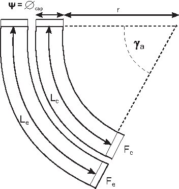
Diagram showing a bending movement in the robot arm. The extensor muscle is pictured on the left of the picture. Only one of the six contractile muscles is shown, the one that is pressurized to obtain the bending (right). The direction of the muscle forces is also illustrated together with the bending angle. The symbol “L” is utilized for muscle length, “r” for the radius of the link arm, “γ” for the angle of the link arm bending, and “ψ” for diameter of the contractor muscle end cap.
By substituting the force equation in (1) for the actuator forces, an expression for contractile pressure is found:
where Pc and Pe are the pressures in the two muscle types and Doc and Doe are the theoretical maximum muscle diameters for the contractor and extensor actuators, respectively, determined using Equation (7) as follows:
θc and θe are the braid angles of each muscle, which using Equation (5) can be determined as follows:
The 3 sets of data containing 150 samples each (total 450 samples) reported in the first three columns of Table 2 are utilized to test this analysis. The contractile pressure measured in the experiments and the one obtained through this simplified mathematical analysis are compared in Figure 10. The discussion about our findings in these figures is presented in following sections.

Relationship between contractile pressure and curvature: comparison between the experimental values, the results of the NN analysis and mathematical analysis. The error bars for the experimental data are vertical because in that case, the data taken into account are curvature. The error bars for the mathematical model are horizontal, since the estimated data are the pressure in the contractile muscles. The neural network data fit the experimental data very well. The error bars for the two NN are so close together that, they cannot be appreciated in this graph and hence an enlargement is provided. The experimental data used for this figure are relative to the 0 kg experiment with expansor muscle pressure of 300 kPa. MLNN, Multilayer FeedForward Neural Network; NN, neural networks; SLNN, Single-Layer FeedForward Neural Network. Color images available online at www.liebertpub.com/soro
NN analysis
In this section, we focus on finding the type of NN among the many types available, which will optimally analyze our device. A first challenge is presented by the unclarity on which type of NN is likely to provide consistent adequate performance in our system. A second challenge is determining suitable parameterization of such NN analysis in terms of combinations of the number of hidden layers and the number of neurons to be used within each layer. The latter is problematic since there is no clear rule on adjusting these parameters. A detailed review of NN can be found in Basheer and Hajmeer 31
To answer the first challenge, in terms of identifying the types of NN modelers that provide consistent performance with our system, a collection of well-known NNs and their cascaded versions are considered. These NN modelers include Single-Layer FeedForward Neural Network (SLNN), 32 Multilayer FeedForward Neural Network (MLNN), 33 SLNN-cascade, MLNN-cascade, radial-based NN (RBNN), 34 RBNN-cascade, generalized regression NN (GRNN), 35 exact radial basis network (ERBNN), 36 ERBNN-cascade, and Cascade-forward NN. A detailed comparison between the performances of these NNs is presented in the Supplementary Data.
At this point the second challenge, the unclarity regarding the most suitable parametrization required to achieve close to optimal performance with these variations of NN, is addressed. A dynamically evolving mechanism is used in which the performance on the validation set is used as the main drive to identify the network that best represents the unseen validation set. The associated prediction of such network with the testing set is considered the final outcome. That is, in this mechanism, a cross-validation (CV) is utilized to generate separate training, testing, and validation sets. Multiple copies of each NN with varying parameterizations are trained with the same training set and evaluated with the validation set. In each fold of the CV, among multiple parameterization choices, the parameterization of NN that yields the most accurate prediction on the validation set is utilized to generate the final answer with predicting the outcome on the testing set. The choice of having multiple NNs evaluated in this mechanism is considered to maximize the chance of finding the best possible NN for the contractile-expansor link. Such mechanism is mainly driven with an accurate prediction of solutions and can be considered inefficient when the required training time is factored. However, the general industrial vision for this type of NN parameterization mechanism is to utilize pools/banks of pretrained NN modelers and in a short and automated calibration phase, identify the most suiting modeler from the bank, a modeler that, out of many, best fits the characteristics of the system in the day or at any moment. In such system, the tedious and time-consuming phase of training the NN modelers is to be performed in off-line mode before deployment of the system. The results are comparable for all NN utilized, but SLNN and MLNN are chosen due to their consistent performance in all experiments. The results of the other NN are not reported in this study for the sake of brevity, but can be found in the Supplementary Data. Both SLNN and MLNN utilize backpropagation in their learning. As a result, this mechanism identifies a set of parameterizations that best suit each fold of the CV and then evaluates the performance with the testing set of that fold. To have a fair assessment, 10 repetitions of 10-fold cross-validation are performed. Matlab 2012 is employed for development and testing of the NN-based modelers and “trainlm” is considered their Training function. The performance of the NN-based analysis is assessed in the Experiment 1 and Experiment 2 described in the following paragraphs.
Experiment 1: predicting contractile pressure from curvature and the extensor pressure of the extensor
In this experiment, similar to the mathematical analysis, the network has two inputs and one output. The inputs of the analysis are the desired curvature and the pressure of the extensor muscle and the output is the contractile muscle pressure.
For the first part of this experiment, the same data reported in the first three columns of Table 2 and used for the testing on the mathematical analysis are utilized. The 450 samples are distributed to 3 sets of training, validation, and testing with 0.8, 0.1, and 0.1 ratios using a 10-fold CV scheme and this procedure is repeated 10 times (
The final results are averaged across folds and repetitions. To remove outliers and possible noisy data points, the mean value of curvature in each set (across 150 samples) is deducted from all curvature measurements. In SLNN, the performance of the approach is assessed against networks with 1–200 neurons using training, validation, and testing sets. The performance on the validation set is used to identify the fittest modeler. The testing set's results of that modeler are reported as output. A similar procedure is utilized in MLNN considering networks with 1–20 hidden layers, each containing 10 neurons. The results of this part of the experiment are illustrated in Figure 10 and show the high performance of NN. In addition to the aforementioned 450 experiments (Old Data), 3 additional sets of data, each containing 150 samples (New Data), are recorded after a new contractile pMA is installed to substitute a broken one.
Considering the old and new data gathered, 900 data points are collected. Analysis of the new datasets indicates a lack of statistical significance both in original and demeaned datasets. The whole experiment is then divided in three phases: (1) using old sets, (2) utilizing both the old and the new sets, and (3) with only new sets; all results are available in Figure 11.

Results of the NN analysis. Overall prediction achieved by MLNN and SLNN modelers across two experimental setups. CM, contractile muscle; EM, expansor muscle. Color images available online at www.liebertpub.com/soro
Experiment 2: predicting contractile and extensor pressures from curvature
The aim of Experiment 2 is to test the performance of an alternative NN setup in which the desired curvature is used as input to the NN modeler and the contractile muscle and extensor muscle pressures are predicted by NN. This setup is designed so that the desired movement can be fed to a modeler and proper pressure configurations for that movement are to be predicted by the modeler. The results for this experiment are shown in Figure 11.
Analysis results
From Figure 10 it can be seen that, while the mathematical analysis results show the general trend, the average percentage error between the experimental and calculated values is 24% for 300 kPa extensor pressure and is even higher at 100 and 200 kPa, reaching a peak of 39%. This is partly due to the fact that only the most basic force analysis is used and it is likely that other analyses, which include friction and other effects, would produce more accurate results. However, this would still not take into account the effect of the ties used to link the muscles together or the interaction between the two contractile muscles as they bend. These effects are likely to be highly nonlinear and so the analysis would still be inaccurate. While it may be possible to generate an analysis that considers these factors, and others, this is likely to be highly complex to generate. On the contrary, as shown in Figures 10 and 11, the exhaustive selection process conducted has identified two NN analyses (SLNN and MLNN) that estimate the required contractile muscles pressure correctly in most cases. Hence, these two NN analyses can reliably describe the relationship between pressure in the contractile muscles and curvature of the arm both with the old and new datasets. A statistical analysis (N-way ANOVA) indicated lack of significant differences between the SLNN, MLNN, and the experimental data; however, the mathematical analysis was found to be significantly different from others (p = 0.0033 < 0.05). Table 3 provides detailed information about the parameter settings of the NN modelers as set by the discussed mechanism within each experiment featuring minimum, maximum, and average number of hidden layers and neurons utilized in the experiments.
CM, contractile muscle; EM, expansor muscle; MLNN, Multilayer FeedForward Neural Network; SLNN, Single-Layer FeedForward Neural Network.
The success in finding optimal NN analyses for our link system is further shown by their ability to estimate two pressures from the desired curvature in Experiment 2. The results of these tests are shown in Figure 11. In this experiment, SLNN performs slightly better than MLNN.
Workspace volume
As has been shown previously, depending upon how muscles are pressurized, the arm will change its curvature and the end of the link will move to a range of different locations. All these possible locations make up the manipulator's work volume. The work volume of the manipulator is approximately described by the difference between two concentric hemispheres. The maximum achievable displacement of the unbent manipulator in the z direction is 90 mm and the maximum horizontal displacement in both the x and y directions is 152 mm from a line projected vertically downward from the center of the fixed end of the link. This information was obtained experimentally by pressurizing different combinations of the muscles to their maximum (500 kPa) and minimum (0 kPa) pressures and recording the position of the end of the link. Figure 12 shows the extremes of the target positions that are achievable.

Workspace of the arm. The work volume of the manipulator is approximately the difference between two concentric hemispheres. Color images available online at www.liebertpub.com/soro
Curvature-payload tests
A number of experiments are performed to characterize the variation in arm curvature by changing the payload and the pressure in the contractile muscles or the extensor muscle. While it is obvious that pressure in the actuators affects the curvature magnitude, it is worth pointing out that, due to the compliant nature of the arm, its curvature is also likely to be varied depending on the weight of the payload being lifted. In an arm as soft as the one presented in this article, loading can cause considerable deviations from constant curvature, leading to large end-effector position error. To test the relationship between payload weight and curvature in this specific arm design a set of experiments has been devised and is described in the following paragraphs.
A first experiment is conducted to describe the deflected position of the manipulator under load. The methodology used to achieve this is as follows: the extensor and two of the inner contractors are pressurized to 500 kPa and the displacement of the end relative to its unbent starting position is measured. This is 210 mm diagonally (i.e., displaced in axes x and z). The arm is then loaded until it straightens to a point where the displacement is 105 mm (i.e., half way to the maximum). The load needed to achieve this is 5.2 kg. The experiment is repeated with the extensor and two of the inner and two of the outer contractors pressurized to 500 kPa. This time the deflection is 215 mm from the start point. The arm is loaded again until it is half way back to the straight location and this needed 7.8 kg. So, the 1.12 kg link has a payload of 5.2 or 7.8 kg depending on if the outer contractors are used, which means that the link can lift 4.6 and 6.9 times its weight.
Further experiments are conducted to describe the relationship between actuator pressures, link curvature, and payload. The experimental setup is described in the next section.
Experimental setup
The data are gathered in the same manner described in Analysis Data Acquisition. Three values of extensor muscle pressure are used: 100, 200, and 300 kPa, and five values of the contractile pressure are utilized: 100, 200, 300, 400, and 500 kPa. Each subset is repeated five times. The testing procedure is time intensive and obtained data suggest a very small standard deviation. Each set of experiments is repeated for a payload of 0, 0.2, and 0.4 kg.
Test results
The results of the experiments with 0, 0.2, and 0.4 kg payloads are shown in Figure 13. The percentage difference of curvature for the three payloads when the extensor pressure is 300 kPa is compared. The difference ranges between 14% and 20%. These results show that the increase in payload affects only slightly the bending behavior of the robotic arm. This shows that the choice of using prevalently contractile muscles in the novel link design grants it enough force to lift a moderate payload without a considerable effect on its range of movement. This is significant for the link performance, as it is the ability to reach high curvatures that implies a broader workspace.

Change in curvature depending on actuation pressure. In graph
To fully characterize the effect of extensor and contractile pressure changes on the curvature of the link, both their effects are analyzed and reported in Table 4. In the first column, the focus is on the effects caused by the pressure change in contractile muscles. In the second and third column, the focus is on the change in curvature caused by the pressure changes in the extensor muscles.
Specifically, in the first column of Table 4, the curvature magnitude is characterized by comparing the percentage difference in curvature between a 100 and a 500 kPa pressure in the contractile muscle pair. Each cell shows a range of values since it is representative of data collected for 100, 200, and 300 kPa pressure in the extensor muscle. All these values are higher than 100%, showing that the novel physical structure is able to attain substantial increase in curvature.
The second column in Table 4 shows the percentage difference of curvature between the case where the pressure of the extensor muscle is set to 100 kPa and the case where it is set to 200 kPa. Each cell shows a range of curvatures relative to data collected for 100, 200, 300, 400, and 500 kPa contractile muscle pressure. The third column in the table shows the percentage difference in curvature between the case when the pressure of the extensor muscle is set to 200 kPa and the case when it is set to 300 kPa. Each cell shows a range over the data collected for 100, 200, 300, 400, and 500 kPa contractile muscle pressure. These data confirm that higher pressures in the central muscle result in higher curvatures of the link. It is possible to appreciate this also by looking at Figure 13 where the 300 kPa extensor pressure results in higher curvatures of the link. The data in Table 4 also show that the increase in curvature for pressures in the extensor muscle from 100 to 200 kPa, second column, is higher than the increase from 200 to 300 kPa, third column. As it can be seen in the plotted data, the standard deviation is consistently low for all experiments.
General Discussion
As seen in Decoupling Length and Stiffness Testing, the percentage difference in stiffness of the contractile-expansor link is 196%, between the softest and the stiffest setup, while maintaining the same length. This shows that the arm can obtain different stiffness without changing the position of the end-effector. Instead, the stiffness of the contractile-only arm cannot be varied without changing its length. Hence, the ability to change the link stiffness without changing the link's length relies on the use of both contractile and expansor actuators in its novel link design. As it can be seen from the graphs (Fig. 6), the relationship between the pulling force and the displacement (stiffness) is nonlinear, but it can be approximated to linear with a small R2.
Another advantage of the use of both contractile and extensor actuators in this design is the ability of the arm to passively return to its initial length. In this arm, the rubber bladder of the extensor acts like a spring to pull the actuator to its minimum length when unpressurised. In contractors, there is no force that pulls the muscle back to its maximum length when they are unpressurised, other than gravity. Hence an arm made only of contractor muscles, as are many in literature, would not go back to its initial position once depressurized.
When measured against other pneumatic manipulators, the arm described in this article has comparable weight and flexibility with the addition of variable stiffness. A central pneumatic actuator is also present in the design of Neppalli and Jones, 37 but in that case, the bending of the arm is provided by cables and not pMAs. The presence of cables can reduce behavioral complexity, but it also reduces the magnitude of the payload that the manipulator can lift. In addition, cables are kept in tension by the motors that actuate them; hence the system is probably less compliant than one made purely of pMAs and requires tensioning maintenance.
To characterize the arm, both a mathematical and an NN analysis of the soft link are performed. Even factoring in the simplicity of the mathematical analysis, results show that the accuracy of the NN analysis is substantially higher. This success is based on the extensive process used to find the best NN analyses for the arm. The automated parameter tuning mechanism utilized with the NN-based modelers also plays a key role in their success by generating a dynamic modeler that is best suited to the training data rather than utilizing a fixed network configuration that only maximizes efficiency with a certain portion of data. As shown in Figure 11, NN-based analyses provide a 70% performance for algorithms in which only the desired curvature is provided as input. The analysis shown in this article is invaluable to show the potentialities of NN in analyzing a system like ours. However, this is only a preliminary analysis, which informs, but does not conclude the research for the modeler needed for the required adaptable control system, as the one shown in Wilson et al. 38 Also, it will only be possible to perform adaptive control once the arm possesses sensors that can provide reliable and robust curvature readings in real time to be fed to the adaptive control.
Conclusions and Future Work
The novelty of this new manipulator's design resides in allowing the variation of the manipulator's stiffness independently from its position in space. High stiffness is needed for tasks that demand position accuracy. Compliance is desirable for tasks that require flexibility and adaptability to the environment. Light weight is a vital characteristic in a robot arm meant to be inherently safe for physical human-robot interaction. As argued in the introduction, these aspects have all been considered in the design of robot arm structures in the literature. However, to our knowledge, in no other case, the arm design combines a completely soft physical structure, the inherent light weight of pneumatically actuated structures, and the ability to vary its stiffness independently of its length, shown by our experiments. It is true that to be operated, a pneumatic system needs a bulky and heavy compressor, but the compressor is mechanically decoupled from the arm; thus it does not increase the possible danger in case of collision with the human user.
The various experiments conducted confirmed that the design of the link allows it to decouple stiffness and length. Also, the experiments show that this novel link design can lift payloads as high as 6.9 times of its weight and the increase in payload has only minimal impact on its curvature. This indicates the aptness of utilizing prevalently contractile muscles in the novel link design. The decidedly higher stiffness of the arm described in this article compared to the stiffness of the purely contractile arm highlights the increase in positioning accuracy potential of our design.
Future work will target a model of the likely nonlinear relationship between extensor and contractile muscle pressure that will allow the change of the structure stiffness for every desired curvature and vice versa. The success in generating an NN analysis that accurately describes the arm's curvature-pressure relationship will inform on the choice of methodologies to achieve an advanced and adaptable control system, which will be a main focus point of future work. An additional aim of future work is to replicate the link described in this article to allow the creation, model, and control of a multilink manipulator.
Footnotes
Acknowledgments
The authors acknowledge support from the EPSRC Centre for Innovative Manufacturing in Intelligent Automation, in undertaking this research work under grant reference number EP/IO33467/1. The second author is supported by the program of the China Scholarships Council (No. 201406080054). No competing financial interests exist. The authors are grateful to A. Baker, M. Irshaidat, M. Sharba, and Dr. H. Hauser for their help with hardware and software components. In accordance with EPSRC and University of Salford rules, the data relative to the research work presented are stored on Figshare, identified by the DOI: 10.17866/rd.salford.5139973. The work described in the article by Giannaccini was conducted while she was employed at Salford University. She is now employed by Bristol University.
Author Disclosure Statement
No competing financial interests exist.
References
Supplementary Material
Please find the following supplemental material available below.
For Open Access articles published under a Creative Commons License, all supplemental material carries the same license as the article it is associated with.
For non-Open Access articles published, all supplemental material carries a non-exclusive license, and permission requests for re-use of supplemental material or any part of supplemental material shall be sent directly to the copyright owner as specified in the copyright notice associated with the article.