
Abstract
Abstract
This article presents the design of a variable stiffness, soft, three-fingered dexterous gripper. The gripper uses two designs of McKibben muscles. Extensor muscles that increase in length when pressurized are used to form the fingers of the gripper. Contractor muscles that decrease in length when pressurized are then used to apply forces to the fingers through tendons, which cause flexion and extension of the fingers. The two types of muscles are arranged to act antagonistically and this means that by raising the pressure in all of the pneumatic muscles, the stiffness of the system can be increased without a resulting change in finger position. The article presents the design of the gripper, some basic kinematics to describe its function, and then experimental results demonstrating the ability to adjust the bending stiffness of the gripper's fingers. It has been demonstrated that the fingers' bending stiffness can be increased by more than 150%. The article concludes by demonstrating that the fingers can be closed loop position controlled and are able to track step and sinusoidal inputs.
Introduction
T
In the future, robots are also likely to work collaboratively with people, and it is essential that this interaction be safe. Although traditional stiff robotic systems are well proven and provide high accuracy and repeatability, their high masses and associated inertias mean they are not suited to close human interaction. 7 Collisions between humans and robots can lead to significant injury; therefore, the traditional approach has been to keep the two separated by a physical barrier. To address this issue and make robot–human interaction safer, a number of approaches have been explored. The simplest solution is to coat the robot in a soft/compliant cover that would absorb impacts; however, this method had only limited success. 7 Introducing passive elastic elements into the transmission system allows motor inertia to be decoupled from collisions, but the technique significantly reduces accuracy. Other methods have included numerous variable stiffness/damping designs such as adjustable spring elements 8 and antagonistic actuators. 9 Although the approaches already detailed remove the forces associated with actuator inertia from collisions, the systems still have massive and rigid links and actuators, which still have the potential to cause significant injury if colliding with a human at anything other than very low speed. 7
Biologically inspired robots have been considered as an alternative method for creating safer robot–human interactions, the aim being to replicate the safe interactions between people and animals in robot systems. One of these approaches uses pneumatic muscle actuators that are inherently compliant and soft in construction to provide an engineering alternative to organic muscles. 10 However, despite soft actuators and compliance, these systems still contain large volumes of rigid mechanical components, analogous to a skeletal system, which are unable to deform and are, therefore, a source of high stress concentration when collisions occur. The relatively new field of soft robotics has potential benefits in this regard. Soft robotics often takes inspiration from biological studies of soft animals such as octopi, which do not have rigid skeletons, and uses this knowledge to develop robots without rigid links. 11 Examples include robots based on caterpillars, 12 the octopus, 13 and worms 14 among others.
Soft robots are highly deformable and can conform to surfaces they come into contact with. If this technology is applied to grippers, it provides two potential benefits. From a safety point of view, it means that in the event of a collision with a person, contact stresses are distributed over a larger area, meaning localized forces are lower and injuries are potentially less serious. 13 It would also provide the ability to distribute forces over a larger area of an object being grasped, again minimizing localized forces and reducing the chance of damaging the object being held. The larger grasp contact area can also result in a more secure grasp than a grip that uses point contracts.
There have been a number of soft robot grippers developed that use a range of different actuation methods. Hassan et al. 15 and Rateni et al. 16 developed a tendon-actuated soft three-finger grippers formed from soft deformable materials, and Giannaccini et al. 17 developed a gripper that used tendons to deform and flex a fluid-filled soft deformable container. Shintake et al. 18 developed a soft gripper based on electroadhesion.
A number of soft grippers have been developed that are fluid powered, both pneumatically and hydraulically powered. Katzschmann et al., 19 Mosadegh et al., 20 and Homberg et al. 21 developed soft continuum fingers consisting of a expanding pneumatic layer sandwiched to an nonextensible flexible layer, which when pressurized flexes. Wakimoto et al. 22 demonstrated a similar actuation method in a microgripper that flexed in different directions, depending on which internal chambers were pressurized. Galloway et al. 23 developed a gripper with a similar principle of operation that used hydraulic power for subsea application. A very different design of pneumatic soft hand was demonstrated by Niiyama et al. 24 The gripper used newly developed hinged pouch motors, which when pressurized caused the joints of the hand to bend.
In most cases, these grippers are unable to change their stiffness. Although highly compliant fingers may be desirable for grasping some products, at other times stiffer fingers may be desirable. Stilli et al. 25 and Maghooa et al. 26 explored controlling the stiffness of a soft manipulator, which used DC motors to apply forces to tendons located along the outer surface of a reinforced pneumatic bladder. The pneumatic system generated an antagonistic force acting against that of the tendons. This allowed stiffness to be increased, as increasing pressure in the pneumatic actuator resulted in higher stiffness.
The research described in this article also explores the concept of variable stiffness in soft grippers. The main contribution of the article is the design and testing of a variable stiffness, three-fingered soft gripper. The article details the development, testing, and control of the gripper. First, the article describes the theory behind the proposed gripper and its capability to vary stiffness. The article then describes the design of two variable stiffness soft grippers before analyzing the kinematics. A series of variable stiffness experiments are then described before the control characteristics of the gripper are assessed at a number of different gripper stiffness levels.
Continuum Actuator
The gripper developed in this work is based on the concept of continuum manipulators. Each of the three fingers is composed of three degrees of freedom continuum manipulator based on McKibben muscles. McKibben muscles are soft pneumatic actuators consisting of an elastomeric bladder surrounded by a braided nylon shell. Depending on their design, they will either contract or expand when pressurized. Note, a muscle can only produce force in one direction (i.e., it is either an extensor or contractor muscle). The resulting fingers are physically soft because of the pneumatic muscles used to form them, meaning that they are inherently safe and also able to easily conform to an object being grasped. Walker 27 demonstrated a continuum manipulator arm based on three parallel pneumatic muscles. Differential pressurization of each muscle resulted in motion of the end of the manipulator.
The fingers in this gripper take inspiration from Walker's design but include an additional actuator to allow the stiffness of the continuum fingers to be adjusted independently of the fingers' position. Each finger is formed from four parallel pneumatic muscles as shown in Figure 1. They consist of one central expansive (i.e., increases in length when pressurized) pneumatic muscle surrounded by three equally spaced contractile (i.e., contract when pressurized) pneumatic muscles. This configuration does not have a direct biological inspiration, although it is superficially similar to a simplified elephant's trunk, wherein the muscular hydrostat is replaced with an expanding muscle.

Variable stiffness continuum finger.
The four actuators used to create each finger are secured to mounting plates at both ends of the finger. Ties are used as shown in the figure to ensure that all the contractile actuators remain equidistance apart along the whole length of the finger and remain in constant contact with the central actuator at all times. The ties are made from flexible nylon cables and are looped through adjacent openings in the central and outer muscles as shown.
The stiffness of a pneumatic muscle is proportional to the air pressure inside it. However, for a fixed load, the displacement is also proportional to pressure—this means position and stiffness cannot be controlled independently. In this novel design, when pressurized, the central actuator creates a force that opposes motion of the outer muscles. Therefore, by increasing the pressure in both the extensor and contractor muscles, the stiffness of the finger can be increased, without a resulting change in position. There are, therefore, an infinite number of actuator pressure combinations that will result in the same fingertip position but that result in a different stiffness.
A variable stiffness continuum finger could be created by using a soft flexible central spine surrounded by antagonistic contracting muscles. However, in such a design, there is a danger than the spine would compress or buckle when the stiffness increases. Having an actuated central section prevents the finger from compressing as it applies a force to resist compression. The combined use of both expanding and contractile muscles means that the length of the finger can also be controlled if desired: a feature that would not be possible if a spine was used.
The other benefit of using a continuum design rather than a system consisting of discrete joints and a flexible covering is that the fingers are able to conform to any shape and operate when partially constrained. This is not possible with a traditional serial manipulator. A redundant manipulator would offer greater flexibility but would still only be able to flex at the individual joint locations.
Soft Hand Design
Figure 2 shows the first prototype gripper developed. Each finger is made of one extensor and three contractor pneumatic muscles as described in Section 2. Each muscle is 135 mm long when unpressurized. The unpressurized diameter of the contactor and extensor muscles is 10 and 15 mm, respectively. Pressurizing each contractor muscle in turn causes the finger to bend in one of three directions. Activation of multiple contractors extends the workspace of the finger to a cylinder as it allows bending of the finger in all directions plus a reduction in finger length if all contractors are activated. As can be seen in the figure, the size of the fingers in this first prototype is much larger than the human hand. This significantly limits the possible applications of the gripper. Although the actuators could all be made smaller, as the force they generate is proportional to their cross-sectional area, this would reduce the grasp strength of the hand.

First prototype three-fingered variable stiffness gripper.
To overcome this problem, a second design has been produced. This design uses the same type of muscles as in the first prototype but, by relocating the contractor muscles and transmitting their force to the finger through tendons, the overall size of the fingers can be reduced to approximately human scale.
Figure 3 shows the conceptual design of the second prototype three-fingered soft gripper. Each of the fingers is made of an expanding pneumatic muscle that has a length of 160 mm and a diameter of 20 mm when unpressurized and a length of 200 mm and a diameter of 15 mm when at the maximum operating pressure of 400 kPa. The fingers are attached to a forearm-like structure consisting of nine contractor pneumatic muscles, each with a maximum length of 240 mm and a contracted length at 400 kPa of 180 mm. These muscles have a maximum force output of ∼200 N at 400 kPa. Each finger is able to vary its length from 149 to 201 mm depending on the relative pressures in the expanding and contracting muscles.

Conceptual design of second prototype soft hand.
As the contractor muscles are located in the forearm, they do not come into contact with the object to be grasped. It, therefore, follows that the actuators applying tension to the tendons do not need to be soft and an electric series elastic actuator could instead be used. However, the gripper is intended to be used on a fully soft manipulator and it is, therefore, vital that the entire gripper, including its actuators, is soft. There are two potential applications currently being considered for this soft manipulator: (i) operation alongside people wherein the system must be inherently safe and (ii) in inspection tasks wherein the manipulator must deform to its physical environment, for example, if inserted into a pipe.
The contractor muscles are arranged in three groups, each consisting of three actuators, with each group providing power to one finger. Nylon tendons are attached at one end to the free end of the contractor muscles and at the other end to the fingertip (i.e., the free end of the extensor muscle). To ensure that the tendons remain correctly located along the length of the finger, nylon loops are added to the outside of each finger through which the tendon passes, as can be seen in Figure 4. These loops ensure that as the fingers bend, the tendons remain in contact with the outer edge of the finger.
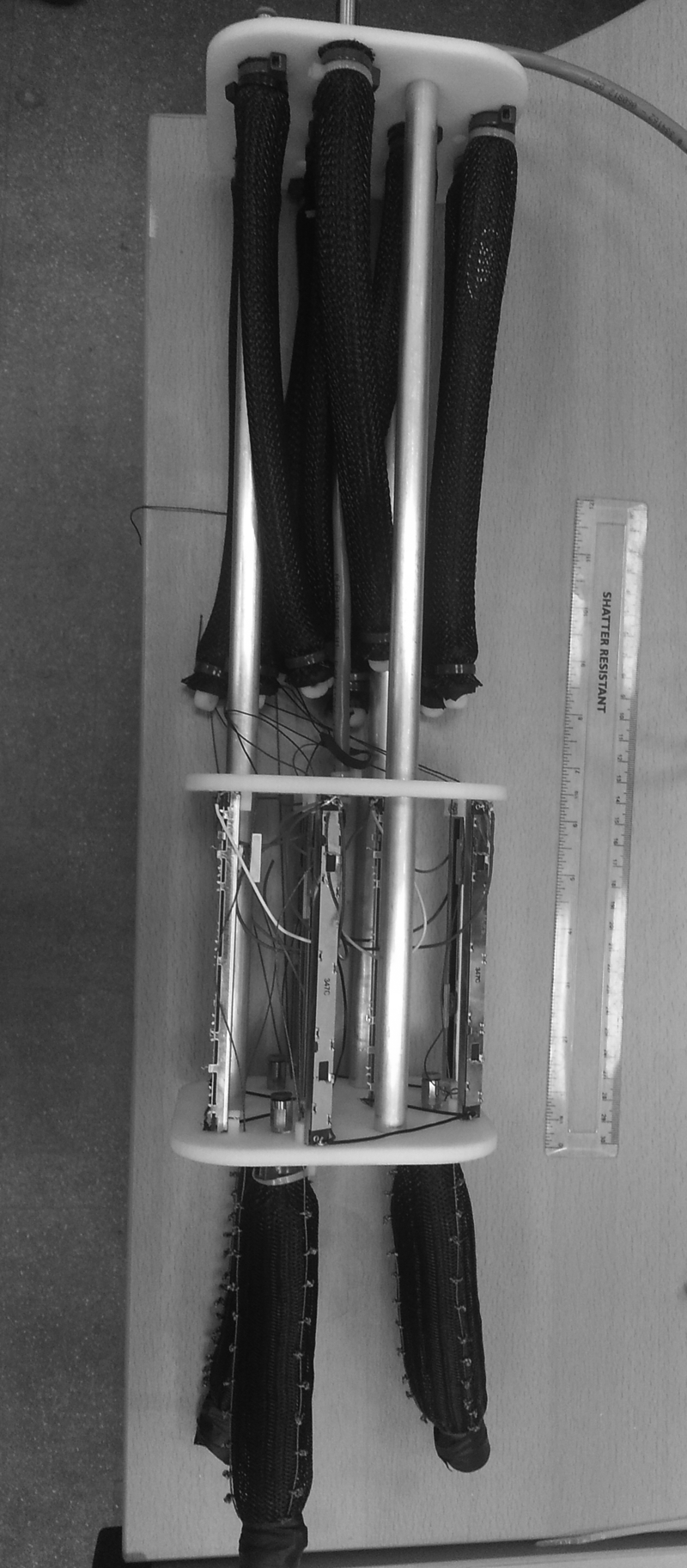
Three-fingered soft hand.
As can be seen, linear potentiometers are located between the extensor and contractor muscles. Each tendon is attached to one potentiometer that is used to measure the displacement of the contractor muscles. These sensors allow the position of the fingertip to be determined using the kinematic analysis described in Section 4 and closed loop control of the finger positions.
Each of the extensor muscles are attached to a single air pressure regulator, allowing the pressure in the fingers to be varied manually. All of the contractor muscles are, however, attached to individual MATRIX 3-3 solenoid valves, which allow air to be supplied to or vented from a single muscle when required. The valves are pulse width modulated (PWM) to allow the flow rate of air into and out of the muscle to be controlled.
Overall control of the hand is provided by an Arduino linked to MATLAB. To allow the Arduino to generate the necessary PWM signals to drive all of the 18 pneumatic valves (9 fill and 9 vent), 2 Adafruit 16-channel PWM/Servo Shields were used to expand the PWM output capability. Amplifier circuits were also needed as the Arduino is not capable of providing sufficient current to power the valves directly.
Finger Kinematics
To determine the position of each fingertip, it is necessary to analyze the kinematics. The position of the fingertip relative to the base is determined by the length of the three outer actuators that are equally spaced around the circumference of the central extensor pneumatic muscle. When the contractor muscles are activated, they will shorten, and as they are attached to the side of the central extensor muscle (through tendons), they will cause it to flex and form a constant radius curve with an arc. The length of the arc is determined by the angular displacement between the two ends of the finger, as can be seen in Figure 5.

Kinematics of continuum finger.
Godage et al. 28 analyzed the kinematics of a continuum manipulator based in three expanding actuators and the same general approach can be used to determine the behavior of the pneumatic finger. Four properties are used to describe the position of the free end of the continuum element relative to the base. The radius of the curve formed is defined as λ, ∅ is used to describe the angular displacement between the two ends of the finger, L is the length of the arc formed, and θ is the angle the end of the element points relative to the base coordinate frame.
The kinematics of the four actuators continuum finger described in this article are given by the following four equations:
Combining (1), (2), and (4), we can determine the length of the finger
where L is the length of the extensor muscle used to form the finger, L1, L2, and L3 are the respective contractions of the three contractor muscles, and ro is the radial distance from the finger's central axis to the contractile actuators.
As the finger is formed from a pneumatic muscle, its diameter is not constant, as it contracts its diameter increases. Therefore, the radial distance of the tendons from the central axis of the finger is equal to the radius of the extensor muscle used to form the finger, which varies with the actuator length. The length (L) and radius (ro) of a pneumatic muscle are determined using the following equations:
where ΘB is the angle of the braid with respect to the central axis of the muscle, b is the length of a single fiber used to form the muscle, and n is the number of times each braid fiber loops around the circumference of the muscle. Combining these two equations with respect to ΘB and substituting in Equation (5) gives the following equation, which relates muscle radius to the length of the three tendons:
Equation (8) can then be combined with Equations (1), (2), and (3) to determine the position of the fingertip relative to the base and is dependent on the contraction of the three contractile actuators (L1, L2, and L3).
It should be noted that this analysis only holds true when there are no external forces acting on the finger, for example, when the gripper is not holding an object. The soft nature of the fingers means that they would deform in a highly complex manner in response to the application of external forces, and a more advanced kinematic/dynamic analysis would be required.
Variable Stiffness Characteristics of Soft Hand
As described previously, the design of the gripper allows for a variable stiffness capability. The stiffness of a pneumatic muscle is directly proportional to the air pressure inside it. In the gripper, the contractor muscles are always acting antagonistically against the extensor muscle used to form the finger. That is to say that if the pressure in the extensor muscle is increased, then to maintain the same finger position, the pressure in the contractor muscles must also be increased. The higher pressure in both the contractor and extensor muscles increases the overall stiffness of the finger. This section of the article explores the variable stiffness capability of the hand.
The test rig used to analyze the bending stiffness of the fingers is shown in Figure 6. The hand was suspended vertically so the fingers were pointing downwards. A tendon was then attached to the fingertip that passed over a pulley to a load. As the load is increased, the horizontal force applied to the fingertip increases and this results in a lateral displacement of the fingertip. This displacement could then be measured and lateral finger bending stiffness was calculated for a range of extensor muscle pressures.

Bending stiffness test rig.
The experimental procedure began by venting all air from the contractor muscles and then using the manual pressure regulator to set the pressure in the extensor muscle to the test pressure required. This generated a force Fe and resulted in the extensor muscle/finger increasing in length. A second pressure regulator was then used to increase the pressure in the three contractor muscles. All three contractor muscles were connected to the same regulator and so produced the same contractile force Fc, as shown in Figure 7. These forces acted, through the tendons, antagonistically against Fe and resulted in a reduction in the length of the extensor muscle/finger (Le). The pressure in the contractor muscles was increased so that the finger length (Le) was equal to that required for the specific bending stiffness experiments described hereunder.

Bending stiffness experimental procedure.
The first bending stiffness experiment was conducted at a finger length of 190 mm. The pressure in the extensor muscle was set to 100 kPa and then the pressure in the contractor muscles was raised so the finger reduced in length to 190 mm. Lateral loads (FLOAD) were then applied to the fingertip in 0.98 N increments, up to a maximum of 9.8 N, and the lateral displacement of the finger was recorded. The experiment was then repeated with extensor muscle pressures of 200, 300, and 400 kPa. Each experiment was repeated multiple times and an average value was determined. Figure 8(a) shows the experimental results. As would be expected, as the force is increased, the lateral displacement of the finger also rises. It can also be seen that when the extensor muscle is at a higher pressure, the lateral force needed to displace the fingertip is higher than when a lower pressure is used.

Lateral finger displacement as load increases at a finger length (Le) of 190 mm
To determine whether the length of the finger had an effect on its bending stiffness, the experiment was repeated with an extensor muscle/finger length of 180 mm. The results are shown in Figure 8(b).
From the experimental results already described, it is possible to determine a bending stiffness value for each of the experiments. This was achieved by producing a linear approximation of the experimental results. At a finger length of 190 mm, the bending stiffness of the finger increased from 36 N/m at an extensor pressure of 100 kPa to 96 N/m at a pressure of 400 kPa. For a finger length of 180 mm, the stiffness increased from 43 to 98 N/m.
Figure 9 shows the percentage increase in finger bending stiffness as the pressure in the extensor muscle is increased. It can be seen that increasing the extensor pressure to 400 kPa results in a stiffness increase of 163% for a 190 mm finger and increase of 112% for a 180 mm finger.

Percentage increase in finger bending stiffness as extensor muscle pressure is increased.
It can be seen that the results are broadly similar for the two finger lengths; however, it was found that the bending stiffness of the finger was fractionally higher at a finger length of 180 mm than when the finger was 190 mm. This result is not, however, unexpected. The force generated by a pneumatic muscle is a function of both pressure and contraction. For a contractor muscle, the force is proportional to muscle pressure and inversely proportional to muscle contractions. For an extensor muscle, force is proportional to muscle pressure and inversely proportional to muscle extension. This means that in the second experiment, for the same pressure, the extensor muscle will be generating a higher force (as it will be extended less). This means that the contractor muscles acting antagonistically will need to generate a larger force, this will require them to have a higher pressure than in the first experiment. Indeed this was observed during the experimentation. A pneumatic muscle can be considered as a variable stiffness spring with the spring constant being proportional to the pressure inside the muscle. Therefore, in the second experiment, the contractor muscles would be stiffer. When a lateral force was applied to the finger, this pulled the tendons and extended the contractor muscle. As the muscle was stiffer than in the first experiment, the displacement would be expected to be less as was observed.
Control
To be of practical use, the gripper needs to be controllable in a closed loop manner. A proportional integral derivative (PID) controller was programmed that controlled the displacement (length) of each of the contractor muscles. PID has successfully been used in the past to control pneumatic muscles as the force/displacement/pressure characteristics can be approximated to linear relationships. 29 As explained in Section 4, the position of each fingertip is determined by the relative length of the three contractor muscles used to power it. The controller reads the displacement from the potentiometer and then generates the necessary PWM signals to control the flow of air into and out of the muscles. The controller was tuned using the Ziegler Nichols method.
To assess the performance of the controller, the response to a step position change was tested along with the ability to track a sinusoidal input.
The experimental procedure for all of the control experiments was as follows. The gripper was suspended in a test rig with the fingers pointing vertically downwards. The pressure in the extensor muscle was manually set to a fixed pressure. The controller was instructed to keep the length of the two contractor muscles on the rear of the finger (furthest away from the center of the palm) at a constant length. The single muscle on the front of the finger was then instructed to contract, which caused the finger to flex. When this muscle relaxed, the two contractor muscles on the rear of the finger caused it to extend again.
Figure 10 shows the controller response to a series of the step inputs that caused the muscle on the front of the finger to contract by 20 mm (a), 30 mm, (b) and 40 mm (c) from an initial starting position. This caused the fingers to flex from an initially straight configuration to a point where the fingertip had displaced ∼50, 65, and 80 mm, respectively, in the horizontal plane.
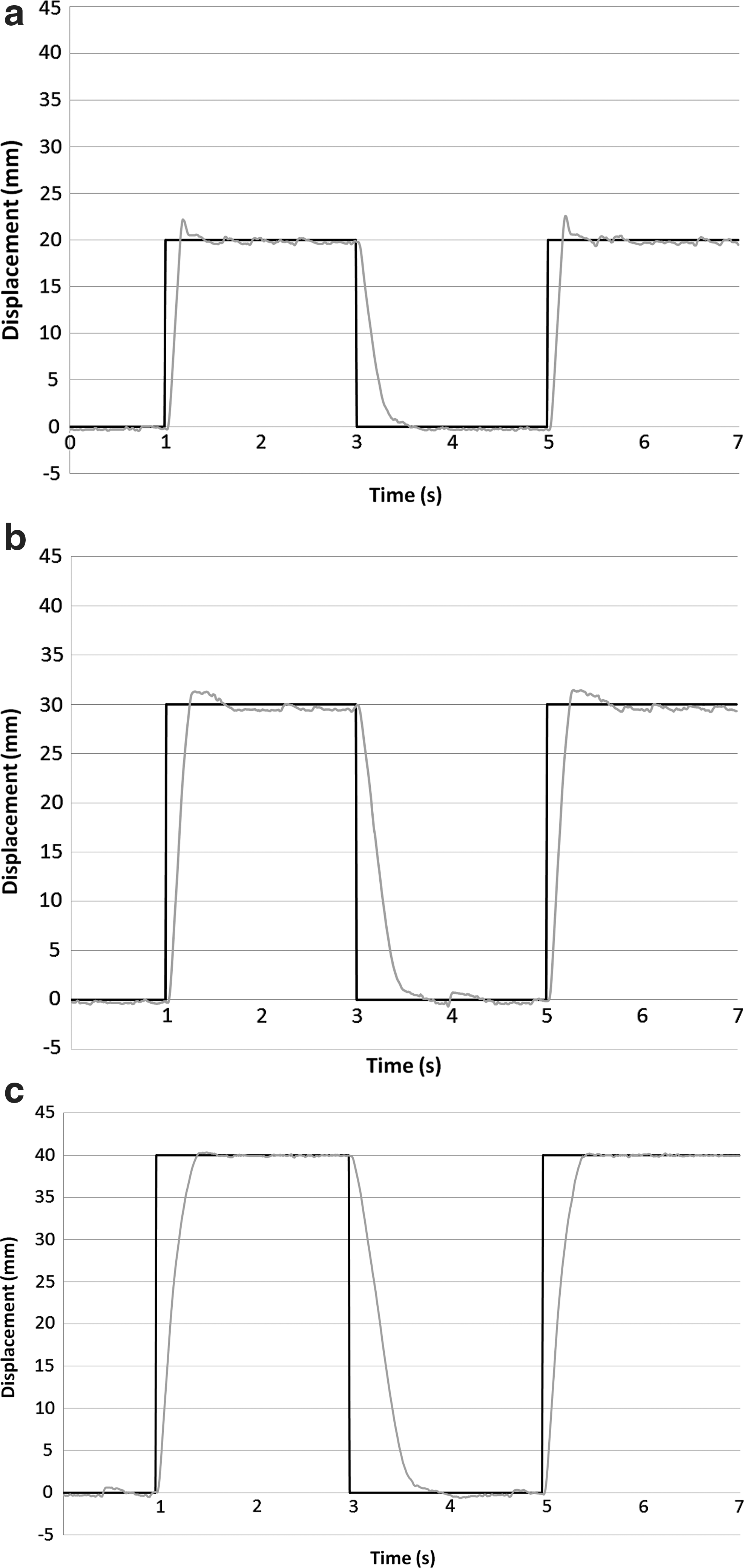
Response to 20 mm
It can be seen that in all cases, the controller overshoots slightly (2.5 mm for the 20-mm step, 2 mm for the 30-mm step, and 0.5 mm for the 40-mm step) before returning to the target position. For all three steps, the controller reaches a point where it is within an error range of ±0.5 mm within 0.46 s for finger flexion and 0.6 s for finger extension.
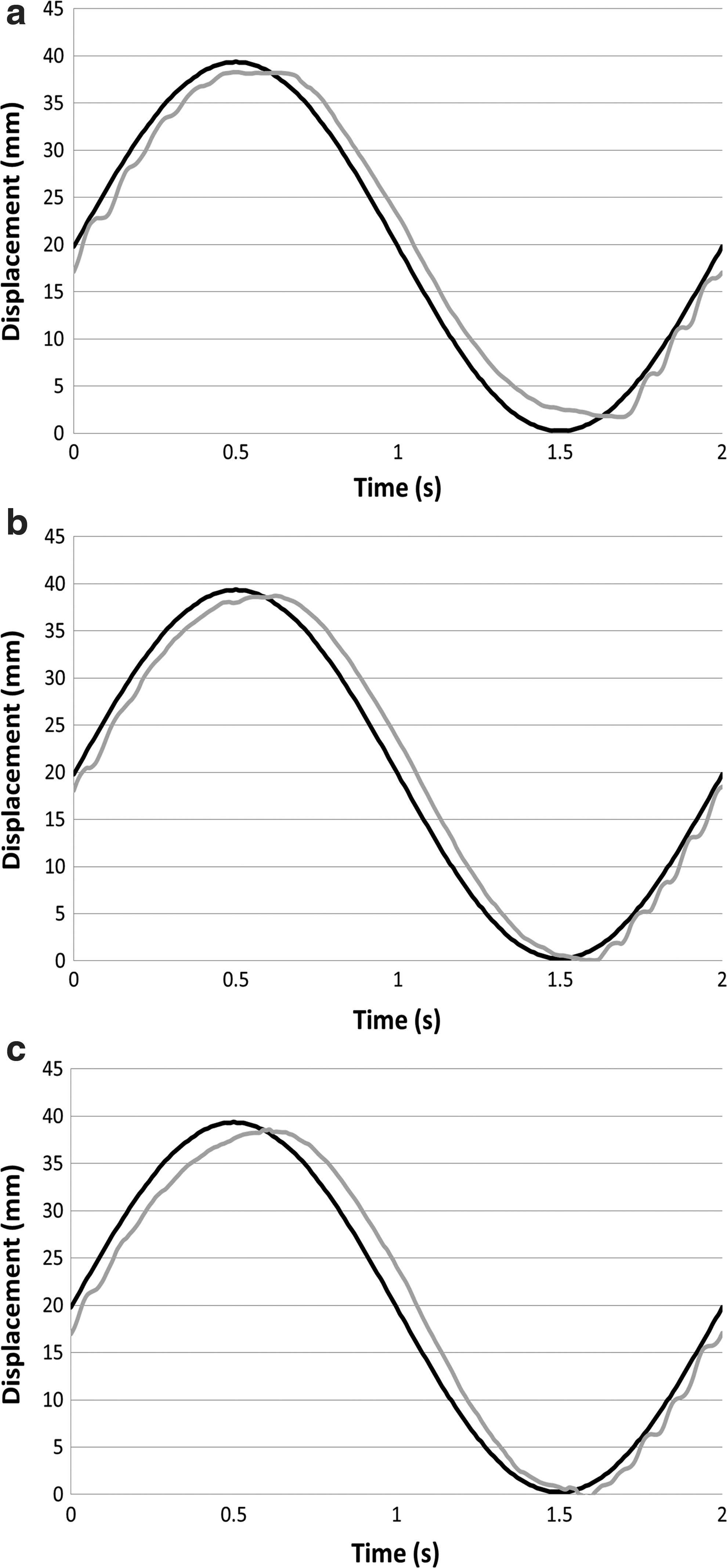
Figure 11 shows the ability of the controller to track a sinusoidal input signal. The range of motion was the same as in the step response experiment, with the contractor muscle causing flexion moving through a 20 mm (a), 30 mm (b), and 40 mm (c) peak-to-peak displacement from the initial position. The experiment was conducted at a frequency of 0.25 and 0.5 Hz.

Response to 20 mm
At 0.25 Hz, the maximum position error was found to be 2 mm and root mean square (RMS) error was 1.1 mm. At 0.5 Hz, the maximum error was 2.5 mm with an RMS error of 2 mm.
As discussed in previous sections, the gripper has the ability to vary the stiffness of its fingers. This is achieved by increasing the pressure in the extensor muscle, which increases the force acting antagonistically against the contractor muscles. This means the pressure in the contractors needs to be increased to counteract the extensor force and maintain finger position. Actuator stiffness is a function of pressure, meaning that the stiffness of the gripper increases.
For the hand to operate in various stiffness modes, it is vital that it can be controlled irrespective of the pressure in the extensor muscle. To determine whether this was possible, step and sinusoidal response experiments were conducted at a range of different extensor pressures. Figure 12 shows the finger tracking a 40 mm peak-to-peak signal with extensor muscle pressures of 100 kPa (a), 200 kPa (b), and 300 kPa (c).
Tracking 40 mm sinusoidal displacements signal with extensor pressure of 100 kPa
The controller gains remained the same in each case, and it can be seen that the finger is able to track the input signal in all cases. By observing the response when an extensor pressure of 100 kPa is used, it can be seen that the finger does not return to the zero displacement position as effectively as when higher pressures are used. The likely reason for this is that when the contractor muscle relaxes, it requires a force to extend it. This force is provided by a combination of the forces generated by the extensor muscle and the contractors on the back of the finger. As the pressures and, therefore, force generated by these muscles are lower, the restoring force is reduced and the finger does not extend as rapidly.
This problem can be overcome by increasing the gain of the controller used to vent the contractor muscle; however, this then creates problems with the accuracy of the tracking when higher extensor pressures are being used. This is not an altogether unexpected result as a PID controller is not able to tolerate the nonlinearities that are likely present in the system, particularly when the stiffness of the gripper is changed.
In the experiments already described, the two muscles on the rear of the finger have been required to maintain a fixed length. However, in some applications, it may be necessary for the controller to change the length of all three contractor muscles simultaneously. To demonstrate whether the controller is able to achieve this and also to demonstrate the gripper's ability to adjust its finger length, a further control experiment was conducted. The experiment involved instructed all three independently controlled contractor muscles to move back and forth in a step between target lengths of 200 and 230 mm. This caused the finger to expand and contract in length across a range of 30 mm. The results are shown in Figure 13; it can be seen that when all three contractor muscles are being controlled simultaneously, the displacement is broadly as accurate as when two of the extensors remained at a fixed length.
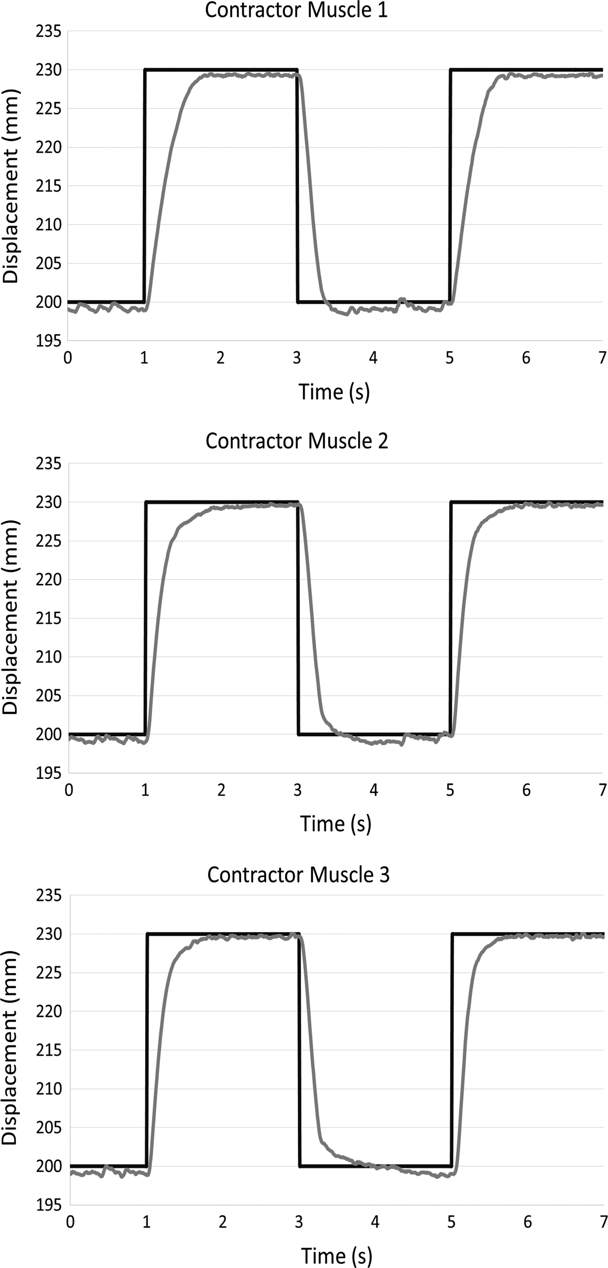
The response of the three contractor muscles when producing a step change in finger length.
The results previously discussed show closed loop position control of just one finger, although the same results were observed for each of the three fingers. To be of any practical use, the three fingers of the gripper need to be used simultaneously. Figure 14 shows the results of grasping experiments. The gripper was demonstrated by grasping a rigid tin can (a) and a soft deformable piece of fruit (b).

The soft gripper grasping sample products.
Although the grasps were successful, the gripper currently only has position sensors, meaning that there was no force control during the grasp. This meant that the finger position necessary to achieve a secure grasp needed to be determined beforehand. The addition of force sensors would remove this requirement and will be explored as future work.
Conclusions and Future Work
This article presents the design of a variable stiffness three-fingered soft dexterous gripper. The gripper uses pneumatic muscles that are soft and inherently compliant. In this design, the pneumatic muscles are used to form the actual fingers of the gripper as well as providing the force to power them. The design uniquely uses a combination of both contracting and extending pneumatic muscles that operate antagonistically. This means that by raising the pressure in all of the actuators, the stiffness of the gripper can be increased without the position of the fingers changing. This gives the gripper the ability to change the position and stiffness of the fingers independently and this has been proven experimentally.
The forward kinematics of the continuum finger have been developed. These are based on kinematic analysis of previous continuum robots, which have then been modified to account for the fact that the distance of the contractor muscles from the central axis varies as the extensor is pressurized.
It has been shown that the fingers can be controlled using a PID controller and are able to respond to a step position change, track a sinusoidal input at different frequencies, and grasp objects. It has also been shown that the same controller can continue to position the fingers even when the stiffness of the fingers is varied.
PID is widely accepted as not being the best technique to control soft robots, which are likely to be highly nonlinear. Although the experimental results have shown that the fingers can be controlled, the accuracy is likely to be greatly improved if other control techniques are used and this will form a large part of the future direction of this research. Other future work will include adding sensors to allow force control to be implemented in addition to position control, as this is of considerable use when grasping objects.
Footnotes
Acknowledgment
This work was supported by the Ministry of Higher Education and Scientific Research, Iraq.
Author Disclosure Statement
No competing financial interests exist.