
Abstract
Abstract
In this work we describe an autonomous soft-bodied robot that is both self-contained and capable of rapid, continuum-body motion. We detail the design, modeling, fabrication, and control of the soft fish, focusing on enabling the robot to perform rapid escape responses. The robot employs a compliant body with embedded actuators emulating the slender anatomical form of a fish. In addition, the robot has a novel fluidic actuation system that drives body motion and has all the subsystems of a traditional robot onboard: power, actuation, processing, and control. At the core of the fish's soft body is an array of fluidic elastomer actuators. We design the fish to emulate escape responses in addition to forward swimming because such maneuvers require rapid body accelerations and continuum-body motion. These maneuvers showcase the performance capabilities of this self-contained robot. The kinematics and controllability of the robot during simulated escape response maneuvers are analyzed and compared with studies on biological fish. We show that during escape responses, the soft-bodied robot has similar input–output relationships to those observed in biological fish. The major implication of this work is that we show soft robots can be both self-contained and capable of rapid body motion.
Introduction
B
In this work, we advance soft robotics by providing a method for creating and controlling autonomous, self-contained, soft-bodied systems. Specifically, we introduce a novel self-contained fluidic actuation system and control algorithms used to deliver continuum motion in soft robots. We demonstrate this soft actuation in a case study by building an autonomous soft-bodied robotic fish powered by an onboard energy source (Fig. 1). The fish is novel in that it uses a soft continuum body and an innovative fluidic actuation system for the soft body and has onboard autonomy. All power, actuation, and computational systems are located onboard. The continuum body has an embedded flexible spine and embedded anatomically proportioned musclelike actuators. The robot is capable of forward swimming and performing agile maneuvers, scaled versions of an escape response.* A fish was chosen as a case study because it naturally exhibits continuum-body curvature, rapid motion during an escape response,1,2 a compliant posterior that bends under hydrodynamic resistance, 3 and an anterior suitable for housing rigid supporting hardware.

Details of a soft-bodied robotic fish. Top: A dorsal view of the fish showing (A) rigid anterior, (B) center of mass, (C) anterior trunk musclelike actuator pair, (D) inextensible vertebrate-like constraint, (E) posterior trunk actuator pair, and (F) passive caudal fin. Center: A cross-sectional rendering of the mechanism showing (G) fluidic elastomer channels grouped into antagonistic actuator, (H) flexible constraint layer, and (I) pressurized elastomer channels in agonistic actuator. Bottom: An exploded view of the robot detailing (J) silicone skin, (K) communication and control electronics, (L) compressed gas cylinder and regulator, (M) flow control valves, (N) actuator access port, (O) plastic fuselage, (P) videography markers, and (Q) silicone elastomer trunk.
We have evaluated the forward swimming and escape response maneuver of this soft robot in a suite of experiments. Extensive kinematic data have been collected on the escape response, and we compare the performance of the robot with various studies on biological fish. We show that our robotic system, although on a different time scale, is able to emulate the basic structure of an escape response and that the performed maneuvers have a similar input–output relationship as observed in biological fish.
Performance and autonomy are competing goals in fluid-powered soft robots. Some fluid-powered soft machines show promising capabilities such as walking 10 and leaping 11 but are primarily driven by cumbersome external hardware limiting their practical use. Conversely, there are instances of self-contained fluidic soft robots;12–14 however, because of the constraints imposed by bringing all supporting hardware onboard, performance of these robots is severely limited when compared with rigid-bodied robots. The primary technical challenge addressed by this work is the advancement of soft-bodied robots to simultaneously be capable of rapidly achieving continuum-body motion and be self-contained. We illustrate our proposed technical approach by designing and building a soft robot fish capable of emulating the escape response of fish because this maneuver exemplifies rapid and continuum-body motion and exhibits the highest accelerations seen in fish. 1
The soft robotic fish exhibits continuum motion that conventional rigid-bodied robotic fish cannot achieve. For instance, although many notable robotic fish exist,15–19 these prior robotic systems have bodies composed of rigid segments connected by fixed joints and are consequently incapable of reproducing the body kinematics observed during agile escape response maneuvers. Previous attempts to recreate an escape response used a body composed of multiple position-controlled, rigid links;20–22 however, such fully actuated, rigid-bodied systems inherently fail to capture the continuum motion of the escape response maneuver.
We build on several prior works that aim to create robotic fish using biologically inspired flexible posteriors. Self-propelling flexible foils driven by an external robotic actuator have been studied by Lauder and colleagues.23,24 Valdivia y Alvarado and Youcef-Toumi used a compliant body in the design of a robotic fish to mimic the swimming kinematics of a natural fish. 25 Similarly, the robot fish FILOSE26,27 has a compliant posterior and serves as a test bed for fishlike sensing and locomotion. Both of these systems are cable-driven and actuated with an onboard servomotor but lack autonomy and require an external power supply. Recently, researchers have developed a cable-driven, flexible spring-steel spine to model escape response behavior; 28 however, in this system the motor, control system, and power supply are external to the apparatus, and its motion is constrained. Long et al. have developed a flexible biomimetic vertebral column used to propel an autonomous surface-swimming robot. 29 The vehicle can also perform an escape response. 30 Again, a single servomotor is used to actuate the compliant spine. Although this system is autonomous, relative to the aforementioned work, only a small portion of the body is flexible, namely, its posterior tail, and because its large anterior is a surface vessel, the system is limited to surface swimming. Notably, the above-mentioned compliant-bodied robotic fish operate on the principle of a passive, flexible mechanism driven by a traditional electromechanical actuator, and they were primarily designed to understand the hydrodynamics of the flexible body. However, in this work our primary goal was to develop a fluidic actuation system that is embedded within the flexible body, yielding a compliant and active body within a completely self-contained system.
We have also built on prior work that introduced compliant active-bodied robotic swimmers. Shen et al. have used an oscillating strip of ionic polymer–metal composite as the posterior trunk of a dolphinlike robot. 31 This is a free-swimming robot, but again limited by an external tether. Perhaps the closest precursor to our work is the Airacuda fish developed by Festo. 32 This robot has a flexible body and is driven by fluidic actuators. Similar to our system, the fluidic and electronic components are located in the fish's rigid anterior, and its actuators extend along the length of its flexible trunk. However, this system differs considerably from ours in design. It is composed of a plastic skeleton covered by flexible skin with two actuators along the anteroposterior axis, whereas we have a body composed almost entirely of soft rubber with numerous actuators embedded in the dorsoventral orientation along the anteroposterior axis (see the Actuation section in Materials and Methods). Another difference is that Airacuda can do static diving and swimming using the onboard pneumatic actuation system, whereas the focus of the fish presented here was on forward swimming and planar escape response maneuvers.
The work presented in this article differs from this prior work in design, fabrication, and control, to enable new autonomous capabilities for soft robotic fish. Specifically, the main contributions of this article include the following:
• A novel fluidic soft actuation system capable of rapidly achieving continuum-body motion • A method for designing, fabricating, and controlling autonomous, self-contained soft-bodied robots • A self-contained soft robot device that embodies our approach to soft robots and emulates forward swimming and planar escape maneuvers of biological fish, along with experimental evaluations of the robot
Materials and Methods
System overview
A defining characteristic of the soft-bodied robotic fish is the separation of actuation power from the rest of the system—specifically, the utilization of mechanical energy in the form of pressurized fluid instead of electrical energy to power actuation. The body of the robotic fish (Fig. 1C–E, G–I, and Q) is entirely composed of fluidic elastomer actuators (FEAs),13,33,34 which are directly powered by pressurized fluid and accordingly no energy conversion takes place at the actuators. However, in order to control the fluidic system, supporting valve hardware is also incorporated into the architecture to electrically address and isolate the mechanical actuation system.
The soft robot has onboard all the subsystems of a conventional robot: an actuation system, power system, driving electronics, and computation and control systems. These systems (Fig. 1K–N) are stored in the fish's rigid anterior region (A), a region with minimal contribution to body curvature during escape responses. 35 Technological advancements in these subsystems enable autonomous operation of a soft-bodied robot underwater.
Actuation
FEA technology forms the core of the soft-bodied robotic fish. FEAs are elastomer modules that bend under fluid pressure. Bending is accomplished using a two-layer bimorph structure. Pressurized gas expands fluidic channels embedded within an elastomer layer, and a second inextensible but flexible layer functions to constrain the axial tension generated by the expanding channels along one side. This transforms lateral stress in the elastomer into a bending moment. Moreover, three layers can be used to form a bidirectional bending FEA: an inextensible constraining layer sandwiched between both an agonistic and antagonistic expanding layer, as has been demonstrated in Ref. 12 This bidirectional FEA structure is fundamental to the soft robotic fish (see Fig. 1G, agonistic layer; H, constraining layer; and I, antagonistic layer). However, in this work we have advanced FEA technology by abandoning a simple rectangular shape and creating FEAs that conform to the complex anatomical shape of a fish. The structure and operating principles of a tapered bidirectional FEA are illustrated schematically in Figure 2.
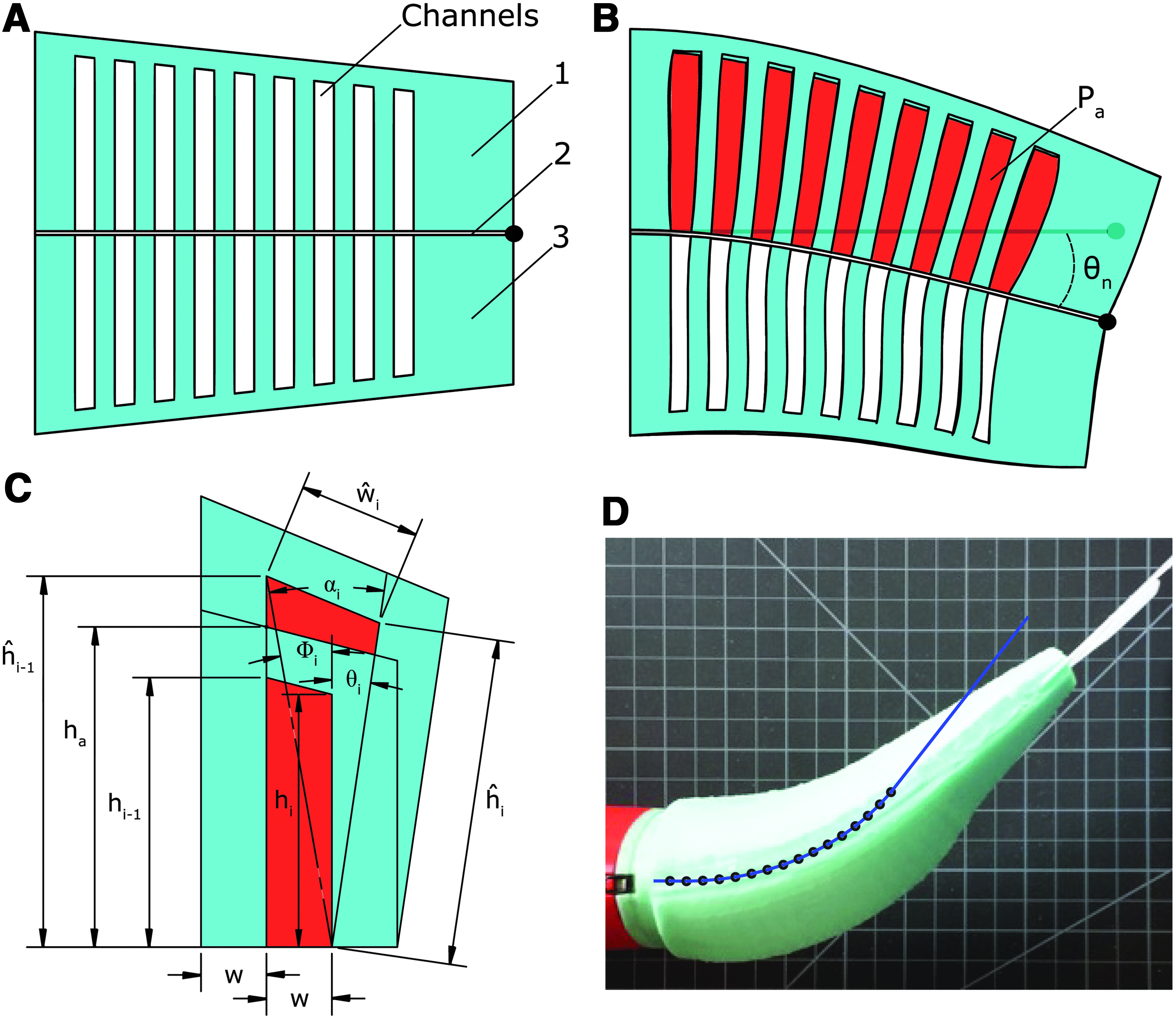
Schematic representation of a tapered bidirectional FEA in cross section.
In their model, Onal and colleagues
13
describe the total bending angle θ of a rectangular FEA using both the physical properties of the channels and internal actuator pressure Pa,
Here, n is the number of channels, w is channel width, ɛ is material strain and a nonlinear function of material stress σ, and, lastly, ha and hc are the constant heights of the actuator and channels, respectively. However, because our actuator differs considerably from a rectangular actuator with uniform channels, we have developed a new model. By extending the model presented in Ref.
13
to include variable channel height as well as radial stress (i.e., normal to the inextensible constraint layer), we can statically model the nonuniform bending of a tapered FEA (Fig. 2). Specifically, the accumulated angle along the length of the actuator after a given embedded channel n, represented as θn, can be estimated as a function of both the physical properties of the preceding channels and Pa,
Here, i is the channel index, αi and Φi are construction angles for the indexed channel, w and ŵ represent the initial and deformed widths of the indexed channel, and h and ĥ represent the initial and deformed heights of the indexed channel. These parameters are illustrated in Figure 2C. It is important to note that this simplifying static model assumes that channels deform purely by extending their side and top walls, and that these wall stresses are based on initial channel geometry. In reality, the wall stresses change as the channel surfaces deform. For this reason, this analytic model is most valid for small deformations, that is, when pressure is low and the actual stresses approximate those calculated from initial channel geometry. The model also ignores external forces such as the compressive forces generated by the antagonistic half of the actuator. In Figure 2D we show a predicted bending of the fish's anterior actuator overlaid on top of the actuator's actual bending. Here, θn was predicted to be 52 degrees but measured approximately 45 degrees. Table 1 lists actuator-specific parameter values for this experiment.
This static analysis suggests that by independently varying the height of embedded channels, net complex curvatures of the body can be achieved. A curvature profile can be mechanically “programmed” into the body geometry of the fish. Such construction serves to simplify computational control inputs. For instance, a single binary control input can be used to drive the robot's body through a complex kinematic profile (Fig. 7).
The robotic fish used in this case study employs four silicone FEAs that are molded to replicate the slender anatomy of a natural fish, creating an actuated but continuously deformable body. The actuated body spans 43% to 100% of the robot's overall fork length (30.5 cm) (Fig. 1, top). Embedded fluidic channels are grouped into two independently actuated pairs: an agonistic and antagonistic anterior trunk pair ranging from 45% to 70% of fork length (Fig. 1C), and a posterior trunk pair ranging from 70% to 90% of fork length (Fig. 1E). Separating the agonistic and antagonistic channel groups is an inextensible but flexible constraining layer introduced along the fish's posterior midline (Fig. 1D and H). This layer enables channel stresses to generate body curvature, analogous to, though inverted from, the process by which muscles generate a bending moment about the vertebrate column in a fish.3,4
A fabrication process was developed to first cast and then combine components of the fish's soft body. The process is illustrated in Figure 3. First, each half of the body is cast from silicone rubber (Mold Star 15; Smooth-on, Easton, PA) by a two-part mold. The top mold piece creates the embedded channels of both the anterior and posterior actuator grouping, and the bottom piece creates the anatomical fish shape (Fig. 3[1a]). In parallel, a connector piece is cast with holes to serve as access ports to each channel grouping and with an internal faceplate, allowing the connector to mate with the fish's rigid anterior (Fig. 3[1b]). In addition, a thin constraint layer is cast with an embedded 0.5 mm Acetal film that provides inextensibility and also forms the caudal fin (Fig. 3[1c]). Next, the four pieces undergo postcasting preparation and are sequentially bonded to each other using a thin layer of silicone (Fig. 3[2]). Once cured, the body is ready for attachment to the rigid anterior (Fig. 3[3]).

Illustration of the soft fish body fabrication process. First, two halves of the body
As mentioned, fluid energy is used to actuate the robot's body. Work is done on the body by the onboard power system. When the body is actuated, a portion of this work is stored as potential energy within the elastomer and compressible fluid, WElastic, and the remainder is dissipated because of friction inside and outside the body, WResistive. In order to characterize the relative amounts of work required to actuate the body at various rates, a pressure–volume analysis technique was used similar to that used to measure the work of breathing.
36
While submerged in water, the agonistic anterior actuator was repeatedly filled to a target volume, VD, as the flow rate into the actuator was varied, ranging from a baseline flow of 5 L/m to a maximum flow of 50 L/m. Both the change in internal actuator pressure, Pa, and change in volume, v, were measured. We assume that at the baseline flow rate, there are no resistive losses and all energy delivered to the actuator is stored elastically,
At each flow rate above baseline, i, the resistive component of work done on the body can be approximated as
Figure 4 shows the pressure–volume profiles at various flow rates as well as an illustration of the work calculations. Table 2 lists the total, elastic, and resistive components of work done on the soft body in water at various flow rates. Here, work is calculated according to Equations 4 and 5 not measured directly. The resistive component of work increases as the actuator is driven at higher rates; however, even at the highest rate of actuation, nearly 78% of delivered energy is stored elastically.

Pressure–volume profiles of fluid used to fill the anterior agonist actuator at various flow rates. By integrating the change in pressure as a function of displaced volume, the elastic and resistive components of work done on the actuator are determined.
Power supply
In order to drive locomotion, there must be an apparatus onboard for supplying fluidic power. In an autonomous soft robot application, it is desirable to maximize the energy density

Details of gas storage, regulation, and release mechanism. The mechanism consists of a high-pressure CO2 gas cylinder (A), a passive mechanical regulator (B), an interface manifold (C), proportional control valves (D), and exhaust valves (E). On the left, red arrows illustrate gas flow during actuator pressurization; on the right, black arrows illustrate gas flow during depressurization.
The total potential energy stored within, E, and energy density, D, of the high-pressure container can be theorized by assuming that the energy release is isothermal and by neglecting fluid phase changes,
Here, the supply pressure Ps is a nonlinear function of volume v, and this relation is defined using the Van der Waals gas law. The volume v0 is the fluid's volume corresponding to the vapor pressure of the gas, Ps(v0)=Pvapor. The volume vf is the fluid's volume at standard temperature and pressure. The volume occupied by the container is V. Table 3 contains application-specific parameters for the power supply. According to Equation 6, the estimated energy density of this power supply is 0.1
Gas delivery
Both an onboard gas regulation mechanism† shown in Figure 5B and delivery system (Fig. 5C and D) are required to distribute the stored fluid to the robot's actuators. First, the fluid is regulated to a suitable driving pressure, Pd, an order of magnitude below supply pressure. Subsequently, gas flows through a series of control valves and into the body actuators. The network of valves and fluid pathways between the regulator and actuators resist fluid flow. Consequently, inlet flow Q to the actuators is driven by ΔP, the pressure gradient between Pd, and the actuator's internal pressure Pa. To ensure that Pd is of sufficient magnitude to drive the body through its target kinematic profile, a relationship between Q and ΔP is theorized.
From our analysis in Figure 4, inlet flows of between 30 and 50 L/m are required for several hundred milliseconds. Within the gas delivery system, Reynolds numbers are in excess of 3×10⁴, above the critical Reynolds number of 2.3×10³, indicating turbulent flow. Assuming fully developed turbulent flow as well as constant fluid density, viscosity, and temperature, we can estimate the ΔP required to drive Q as follows:
where ρ is the fluid's density, g the gravity, and hT the total head loss of the fluid delivery system, defined as,
where i indexes the n serial pathways within the fluid delivery system, L and d are the length and diameter of the pathway, Kj the loss coefficients of a pathway containing m losses, and f the friction factor as defined by the Haaland equation. 37
Specifically, we calibrate Equation 8 to characterize the case of maximum excursion. Here, the anterior agonistic control valve is fully open, the antagonistic valve is fully occluded, and for simplicity we ignore the posterior actuator pair. The fluid pathway has three main parts: (1) the section between the regulator and valve orifice, (2) the valve, and (3) the valve to the actuator inlet. Pathways 1 and 3 are designed to minimize resistance and accordingly contribute little to hT. However, constraints on valve performance and size force pathway 2 to be of high resistance. Finite element analysis was used to estimate losses (ΣK) (see Table 3 for parameter estimates). As a result of this analysis, ΔP is required to be between 0.06 and 0.10 MPa, and considering the range of Pa in Figure 4 and commercial availability, a regulator providing a Pd of 0.29 MPa was chosen.
The above analysis suggests that the gas delivery system is responsible for considerable resistive energy losses. Given an anterior actuator frequency of f, we can estimate the losses of this subsystem over a single bidirectional actuation cycle:
Processing and control
The robot contains an onboard microprocessor‡ and wireless communication module§ that enable it to both process external inputs and execute control policies. This computational system interfaces directly with onboard hardware such as control valves and any available sensors. Two proportional valves** are used to control the pressurization of the agonistic and antagonistic anterior actuators, and two exhaust valves†† control depressurization. Two solenoid valves‡‡ control pressurization and depressurization of the posterior actuator pair. Depressurization of the body actuators is primarily passive. The exhaust and solenoid valve orifices resist fluid outflow, and the actuators act as fluid energy storage devices, analogous to a capacitor in the electrical domain. If we ignore the fluid's negligible inertia, we can represent actuator depressurization as an undriven first-order system, analogous to a capacitor discharging through a resistor. The instant the exhaust valve is open, the pressure gradient driving exhaust flow is equal to Pa, and the flow is at a maximum. Subsequently, the flow exponentially drops to zero. Although the computational system can provide onboard autonomy, the robot wirelessly communicates with a host PC to receive user commands. The fish is negatively buoyant and held at a fixed submergence by means of a floating support.
The control policy of fully actuated fish locomotion can be described using seven parameters, T1, M1, T2, M2, φ, T3, and T4. The anterior control valves are driven using a square-wave input, and agonistic and antagonistic valves are energized sequentially ensuring while one actuator is pressurizing the other is exhausting. Here, T1 and T2 are the open periods of the anterior agonistic and antagonistic actuator proportional control valves, respectively. The corresponding orifice magnitudes M1 and M2 of these control valves are defined as a percent of maximum available flow. The parameter φ is the phase delay between the anterior and posterior actuator pairs, and T3 and T4 are the open periods of the posterior agonistic and antagonistic actuator control valves, respectively, and their magnitudes are fixed. However, the body can also be driven as an underactuated system where fewer than the total number of available actuators are used. For forward locomotion, this abbreviated policy can be parameterized using only T1, M1, T2, and M2. For escape responses, this policy can be further reduced to using only T1 and M1. During escape responses, the posterior agonistic actuator is also used, but T3 is set equal to T1.
Results
Locomotion
As mentioned, the fish's body can function as an underactuated system, where a single control input can excite multiple modes of motion. Using just the anterior actuator pair as opposed to all four available actuators for forward swimming allows the fish to conserve the limited fluid energy stored onboard. Similar to the work of Valdivia y Alvarado and Youcef-Toumi, 25 our fish can use anterior trunk actuators to excite movement in the entire compliant body, producing fast forward swimming. During the experiment detailed in Figure 6, the fish operated using an open-loop controller, and its objective was to swim in a straight line. Here, the posterior trunk actuator pair was passive, the anterior trunk actuators were periodically driven at 1.67 Hz, and linear velocities of 150 mm/s, or 0.44 body lengths/s, were attained. Approximately 30 tail beats were available from the 8 g CO2 cylinder under these experimental conditions. Forward locomotion performance parameters were measured using a high-speed video camera and a mirror mounted at 45 degrees underneath the robot. Video was recorded at 300 fps, and nine colored points along the robot's dorsal midline were digitized during postprocessing.

Experimental results of the robotic fish during forward swimming. The top panel shows the digitized average body midline position moving as a function of time. The bottom panel details the corresponding linear velocity of the center of mass as a function of time. During this experiment, tail stroke frequency is 1.67 Hz, and a velocity of approximately 150 mm/s is attained.
The forward-swimming results show that the self-contained actuation system is capable of sustained operation, exemplified by forward fishlike locomotion. However, the swimming gait we present here is certainly suboptimal. A comprehensive sweep over driving pressures, tail frequencies, and body stiffness would allow optimization of forward locomotion.
Escape response
A critical behavior exhibited among fish is an escape response, which involves rapidly bending the fish's body to large angles in order to accelerate away from adverse stimuli. Experiments were conducted to investigate the escape response of our soft-bodied robotic fish and compare its maneuvers to that of natural fish. A total of 28 escape response experiments are reported and were carried out in a 76-cm-long by 76-cm-wide by 61-cm-tall water tank filled to 41 cm. The robot was completely submerged and held at an initial fixed submergence by means of a 172-cm-long nylon string. Escape responses were generated using an open-loop controller. Escape response performance parameters were measured using the same high-speed videography techniques as listed for the forward locomotion experiment; however, here the camera was positioned overhead. Heading angle is defined in degrees as the rotational displacement of the rigid anterior midline. Escape angle is defined as the resulting heading angle after the maneuver when the angular rate drops to zero. Linear escape velocity is defined as the Cartesian velocity of the center of mass 500 ms after the onset of the maneuver.
Fish 30–40 cm in length (rainbow trout and northern pike) have been shown to perform type I, or single-bend, escape responses where the body initially bends into an “S” shape and subsequently into a “C” shape with heading angles greater than 90 degrees. 38 Our robot exhibits fishlike mechanisms to accelerate (see the exemplary single-bend escape response in Figures 7A–D and 8A). We create single-bend responses by using only the anterior and posterior agonistic body actuators. Here, from 0 to 150 ms the body's midline assumes an “S” shape with the caudal fin curving in the opposite direction of the trunk. From 150 to 500 ms the body's midline assumes a “C” shape as the caudal fin, peduncle region, and trunk exhibit the same direction of curvature. The robot reaches a maximum heading angle of 100 degrees at approximately 520 ms. The aforementioned natural fish also exhibit type II, or double-bend, escape responses characterized by the fish's anterior region bending away from the posterior midline's primary direction of curvature as the body assumes a “C” shape. 38 In Figures 7E–H and 8B, the robot performs a double-bend escape response using both anterior and posterior agonistic and antagonistic body actuators. Here, the “C” shape is assumed at 170 ms and is quickly preceded by the body straightening. A maximum heading angle of 72 degrees is obtained at 410 ms. In general, the robotic fish exhibits higher escape angles in single-bend than in double-bend escape responses. Figure 9 portrays both a single- and double-bend escape response of an angelfish (body length of 7.3 cm) exhibiting a similar kinematic pattern to our robot; that is, the angelfish is also shown to have higher escape angles in single-bend than in double-bend responses. 39

Sequences depicting the soft robotic fish performing both a single-bend

Escape response kinematics of the soft-bodied robotic fish. Panel

Fast-start kinematics of an angelfish. At the top is the body midline plotted for a single-bend
Foreman and Eaton 40 document that single-bend maneuvers in fish result in higher escape angles and slower center-of-mass motion, while double-bend maneuvers result in lower escape angles and faster center-of-mass motion. Consequently, although antagonistic effort is not required for center-of-mass motion, it is responsible for amplifying the center-of-mass motion and a period of negative angular rate in natural fish. An important result is that our robot exhibits similar behavior: In double-bend responses, escape angle is lower and linear escape velocity higher than in single-bend responses. In double-bend escape responses having antagonistic actuator activity (Fig. 8B), the escape angle is reduced, as there is significant angular rate in the negative (antagonistic) direction starting at approximately 380 ms (60 ms after the completion of antagonistic activity). Onset of significant center-of-mass motion occurred at 160 ms, approximately synchronized with the onset of antagonistic activity.
A point of contrast is that in natural fish the head and tail both move toward each other in the first stage of the escape response (Fig. 9). However, because the center of mass of our robot is in the anterior head region, head movement is greatest during the second stage of the escape response.
Eaton, Lee, and Foreman's direction-change hypothesis in natural fish 41 is consistent with the behavior of our robotic fish. Specifically, a combination of agonistic and antagonistic actuator inputs can independently influence both escape angle and linear escape velocity during the robot's escape response. A series of experiments were carried out to investigate the effect of two parameters, T1§§ and M2, on the escape angle and linear escape velocity of the robotic fish (Fig. 10). As a result we found that T1 has marked influence on escape angle. Mean escape angle at T1 equal to 100 ms was 26.6 degrees, whereas mean escape angle was 81.4 degrees at T1, equal to 160 ms. Also, M2 provides control over escape angle. Increasing M2 decreased escape angle (Fig. 10A). Unlike escape angle, T1 has minimal influence on linear escape velocity, mean values of 193.1 and 207.2 mm/s for 100 and 160 ms, respectively. However, M2 provided control over linear escape velocity in that increasing effort level exponentially increased velocity (Fig. 10B). These findings indicate that through a combination of agonistic and antagonistic actuator efforts, escape angle and linear escape velocity can be independently altered. Given a fixed maximal agonistic effort level, altering T1 and M2 can independently influence both the resulting escape angle and escape velocity.

Input–output relationship of escape response maneuvers in the robotic fish.
Discussion
The robotic fish provides an instantiation of our approach to creating autonomous soft-bodied robots capable of rapidly achieving continuum-body motion. In this system, soft musclelike actuators generate curvature in a continuously deformable, vertebrate-like body. Novel, form-independent actuator technology as well as miniaturization of supporting hardware enable the robot to take on the fundamental anatomical structure of a fish while being self-contained and unconstrained.
The programmability of our system allows repeatable evaluation of the robot's escape response maneuvers. By directly controlling the duration and magnitude of agonistic and antagonistic actuator efforts and measuring the resulting escape response performance, we conclude that agonistic duration has strong authority over escape angle and minimal authority over linear escape velocity. Antagonistic magnitude has nonlinear control authority over both escape angle and escape velocity. Increasing agonistic effort duration allows for greater angular displacement of the head to be reached during the first stage of the response. Soon after this duration of time, the robot's head begins to decelerate. The longer the agonistic effort is applied, the greater the escape angle. When antagonistic effort magnitude increases, there is more energy to decelerate the turn and consequently escape angle lowers. The antagonistic effort also provides the propulsive stroke, so greater antagonistic effort yields higher escape velocity.
Evidence suggests that a similar input–output relationship holds in biological escape response behavior. Consistent with our robotic system, Foreman and Eaton 40 presented the direction change concept, where they show that escape response heading angle is a function of the relative magnitudes and timings of agonist and antagonist muscle contractions. Wöhl and Schuster 42 investigated the predictive start of hunting archer fish and showed that in the underlying C-start behavior, escape angle and escape velocity need to be decoupled. Also in line with our robotic system, Tytell and Lauder 43 found that, among investigated variables, stage-one duration correlated most strongly with escape angle and that antagonistic effort magnitude correlated most strongly with escape velocity in biological fish.
Our findings also suggest that despite the apparent complexity of the maneuver, it is feasible that a robotic system with limited onboard computational power could determine required escape response control parameters in real time and with no a priori planning. Because the robot's escape response performance outputs, angle and velocity, are inherently decoupled by the physical form of the body and structure of the maneuver, control parameters could potentially be computed onboard. For instance, the maneuver may start in immediate response to a perceived external stimulus with a predetermined maximal agonistic effort. As this effort occurs, the desired escape angle and velocity may be computed relative to the perceived stimuli. Accordingly, the control variables T1 and M2 can be determined given a mapping similar to that provided in Figure 10.
Footnotes
Acknowledgments
A special thanks to Robert Katzschmann from the Distributed Robotics Laboratory and the Soft Robotics reviewers for their extensive feedback. This work was done in the Distributed Robotics Laboratory at MIT with support from the National Science Foundation (grant numbers NSF IIS1226883 and NSF CCF1138967) and National Science Foundation Graduate Research Fellowship Program (primary award number 1122374). We are grateful for this support.
Author Disclosure Statement
The authors declare no competing financial interests exist.
*
Escape response maneuvers are characterized by rapid body accelerations over very short durations and that often involve the body initially bending into a “C” shape. 1 Among vertebrates, these are some of the most rapid maneuvers 4 and subject of frequent study. The extremely agile behavior exhibited by fish during escape response maneuvers is central to predator–prey interactions, 5 and accordingly escape response performance carries marked ecological significance.6–9 Recently, the hydrodynamics of the maneuver have been explored in great detail. 2
†
0.29 MPa regulator (PN 50044; Leland Ltd., Inc.).
‡
Atmega 644P (Atmel Corporation, San Jose, CA).
§
XBee-PRO 900 (Digi International Inc., Minnetonka, MN).
**
PN 921-111051-000 (Parker Precision Fluidics).
††
PN PND-05A-12 (Parker Precision Fluidics).
‡‡
PN 914-232123-000 (Parker Precision Fluidics).
§§
T1 = T2 in all tests.