
Abstract
Pose measurement and contact realization for soft robots are important but are also challenging to perform. In this article, a new approach is proposed which uses light transmission through the bore of the robot to sense its pose. By combining optical signals with inertial measurement units and pressure signals, along with governing models and machine learning algorithms, this sensing approach allows us to measure the pose of the soft robot in free space. It also allows the applied machine learning algorithm to estimate the robot configuration during contact events, predicting the location, direction, and magnitude of the contact force by learning from prior contact data in a training phase. The sensing devices used are affordable and widely available so that the robot can be mass-produced. Experimental results show that the proposed sensing system successfully estimates these quantities with good accuracy.
Introduction
Soft robots differ from traditional robots in that there is no universally accepted method for representing their configurations. Most current methods for predicting their configuration fail when the robot contacts objects in its environment. Ironically, this ability to accommodate environmental objects is considered a key benefit of soft robots. Soft robots can operate based on various principles, such as pneumatic, hydraulic, textile, tendon, origami, magnetic, or explosive mechanisms.1–4 Pneumatically actuated soft robots are popular due to their high power-to-weight ratio and ease of implementation. 5
Reconstructing the motions of soft robots from measuring devices is challenging due to their continuum nature.1,6 Besides external systems such as motion trackers and cameras, several embedded sensing approaches have been proposed to measure the pose of soft robots. Common methods include resistive strain sensors,7–9 capacitive strain sensors,10–12 and optical waveguide sensors.13–17 Optical waveguide sensors are reportedly more reliable as they avoid soft-rigid connections between sensing parts, 6 utilizing optical fibers or stretchable waveguides for internal light propagation.
Determining contact information, such as force and location, is crucial for controlling soft robots. Tactile sensing methods, such as smart braid, 18 e-skin,19–20 and artificial skin, 21 are expected to equip soft robots with the ability to feel contact events. However, challenges with sensor integration and embedding large-area sensor arrays limit their application. Recently, using optical fibers in tactile sensors has grown due to their flexibility, electromagnetic immunity, high sensitivity, lightweight, and distributed sensing capabilities.22–25 However, embedded sensors often alter the viscoelastic properties of the elastomer walls, affecting its designed functionality.
Several works detect contacts for soft robots indirectly without tactile sensors. For instance, Chen et al.
5
proposed a model-based approach for detecting contact location in a 1-Degree-of-Freedom (DoF) pneumatic bending robot, but this method is limited to planar motions and requires an external camera. Della Santina et al.
26
developed an observer to estimate contact forces for a soft robot operating in
In this article, we describe a new sensing strategy for soft inflatable robots. Instead of embedding multiple tactile sensors in the robot’s body, our technique uses the robot’s hollow bore as a waveguide to transmit light. Changes in light transmission due to contact with the environment are analyzed by a machine learning algorithm to predict configuration, contact location, and force during operation. Chamber pressure sensors and inertial measurement unit (IMU) signals are also used in the training process.
We enhanced the original piece-wise constant curvature (PCC) model to have the segmented curved strip (SCS) approach to better represent the robot’s configuration in free space, accommodating “bending” and “turning” motions. However, when in contact with external objects, the SCS assumptions may no longer be valid. Upon detecting contact, we switch to the Disc-Thread model,27–28 which uses discs connected by threads to represent the soft robot configuration. This model can address complex behaviors like folding, kinking, and twisting, though it imposes a greater computational load. By switching between the SCS and the disc-thread model, we leverage each approach’s strengths to reconstruct the robot’s pose in free space and during contact. Our method identifies all contact information, enabling better control of the soft robot. It uses only low-cost sensors fully integrated inside the robot, making it more practical for applications as it does not rely on external measuring systems like 3D motion trackers or cameras.
Material and Methods
Fabric-reinforced inflatable soft robot “squishy”
This method is demonstrated on a fabric-reinforced inflatable soft robot named “Squishy”. 29 It features a curved chamber made of Smooth-On Dragonskin 30 silicone, with an inextensible fabric embedded longitudinally on one side. When inflated pneumatically, the robot bends and turns towards the fabric side due to the larger strain of the unreinforced silicone chamber wall on the opposite side. The robot’s structure and dimensions are shown in Figures 1–3. The chamber’s neutral shape and fabric position cause the robot to trace a non-planar curve with inflation.
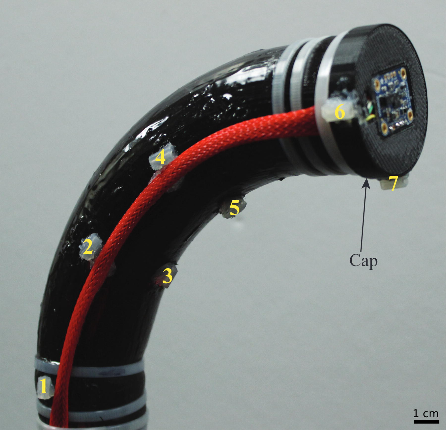
Soft robot squishy with the cap and the numbers showing the location of polhemus sensors.
Optical sensors configuration
Since the inflatable chamber is empty, we use the robot’s bore as a waveguide to transmit light. We installed four mini photocells (Sparkfun GL5528) on the inside surface of the cap (Fig. 1) to measure light from a white LED (Adafruit 754) at the robot’s base (Fig. 2B). The inner chamber surface is painted red to reflect red light, as photocells are least sensitive to the red wavelength (700 nm), preventing chattering when the robot vibrates. The outer surface is painted black to block ambient light infiltration. We used a mix of Smooth-On Silc Pigment, Psycho Paint, and Novocs solvent for painting, ensuring the colors adhere to and expand with the silicone wall. As the robot bends and turns, reflections from the inner wall change and the level of bending and turning is represented in the output voltages from each photocell. Figure 2C shows photocell signals as the robot is inflated from 6.89 kPa to 20.96 kPa and then deflated back to 6.89 kPa, undergoing free space motion.

The optical sensor architecture illuminates the bore of the robot and therefore, it can be used wherever a sufficient amount of light can be transmitted from the emitter to the sensor. This could be duplicated for multi-chambered robots, however there is some possibility of cross-talk between chambers as light can be transmitted through the silicone. This is why we used black paint on the exterior of the chamber to obscure ambient light.
IMUs and pressure sensor
In addition to the photocells, we use a pair of Adafruit BNO005 IMUs to track the robot’s tip orientation. These IMUs are installed perpendicularly (see Fig. 2B) to ignore the roll angle, which is subject to drift, while still providing sufficient orientation information. When the robot contacts an object and deviates from its natural free-space curve, the IMUs offer richer data for learning contact events. In addition, a Honeywell pressure sensor (SSCSANN 001BGAA5) measures the pressure inside the robot chamber.
SCS modeling of the robot in free space
The soft robot’s undeformed longitudinal shape is a quadrant of an annulus with the dimensions shown in Figure 3A. The robot is fixed at the proximal end of a bench, with the cap installed at the tip (Fig. 2B), and starts with an initial pressure of 6.89 kPa. When inflated pneumatically, the radius of the annulus

SCS descriptions
PCC modeling29–30
does not capture the deformation of this robot well, because each segment must be a planar circular arc. Our approach uses three parameters (
The center strip’s width increases as the robot bends laterally towards the fabric side due to chamber inflation (Fig. 3C). The robot operates within its safe pressure range (6.89–20.96 kPa) and adheres to the following assumptions:
All disc centers lie along the same center strip The radius Each segment has the same lateral radius
We placed Polhemus Liberty (Colchester, VT) markers at the locations shown in Figure 1 and recorded their locations and orientation as ground truth. To relate photocell signals to the corresponding free-space motion, we investigated the photocells’ responses and compared them to ground-truth bending and turning measurements. Empirically, we found that photocells 3 and 4 can represent the three motions (changes in
We developed empirical equations proposed by To et al.,
17
to calculate the SCS parameters. Specifically, to calculate the vertical radius
In the same manner, the lateral radius of the fabric
For turning motion, we developed Equation (6) to calculate the turning angle
Given the arc length
In the same manner, each lateral bending angle between disc
With the radii
Not only does the robot bend and turn as the chamber pressure increases, but it will also expand radially. Thus, the radius
The SCS model is a mathematical device that is used to parameterize the motions of the soft robot chamber. In this sense, it can be used to parameterize the deformation of any soft inflatable chamber whose motion is dominated by “bending” and “turning” motions as described in this article. Although the mathematical “strip” is not to be conflated with the physical, fabric strip, the elongation of the robot is not captured by the SCS model. For this reason, the robot must possess a fabric strip or similar strain-limiting layer, so that elongation is prevented and the parametrization will adequately capture the chamber’s motion.
Disc-thread modeling of the robot in contact cases
When the soft robot contacts an object, the object may force each part of the body to bend in different directions or even twist, so the SCS model will no longer accurately represent the robot’s configuration. Thus, if the robot is in contact, we use the recently developed disc-thread model. 28
In the disc-thread approach, each discretized disc is assumed to be connected to its neighbors on either side by an inextensible thread (representing the fabric reinforcement). Unlike SCS, where adjacent discs must follow the bending and turning deformations of the annular segment described in the previous section, the disc-thread model allows a given disc to rotate and translate in any fashion relative to its neighbors, as long as a constant length of the “thread” connecting them is maintained. The frame assignments and their implications are illustrated in Figure 4.

Disc-thread model configuration with
Contact experiment setup
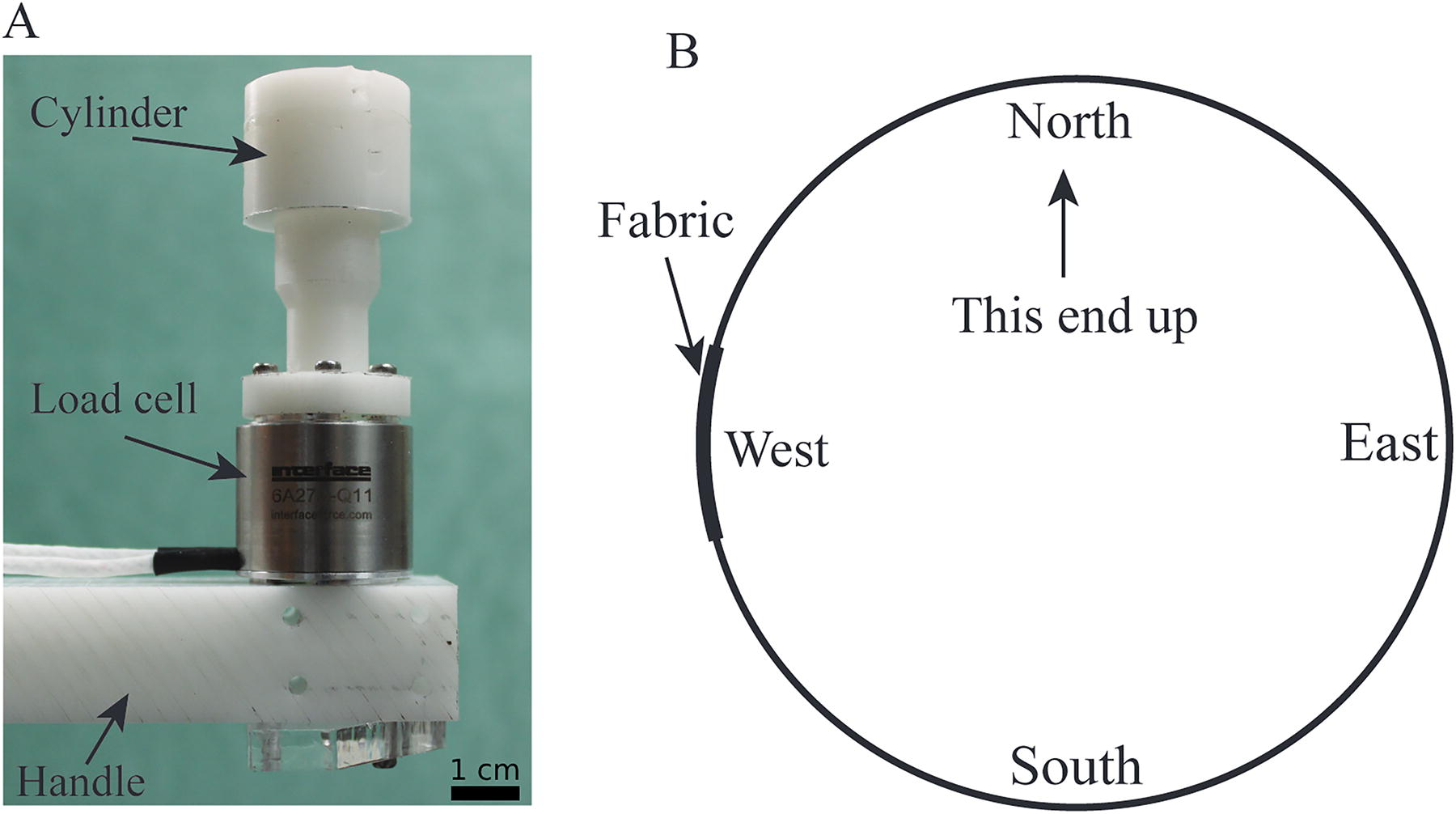
When the soft robot is contacted by an object at various positions and directions, its body deforms accordingly. All state changes during a contact event are fully recognized by the IMUs at the tip and the optical sensing along the entire robot body. Contact was made at each of the three distal-most discs (since disc 1 is stationary). Starting from rest at a fixed pressure (13.78 kPa), a load cell (Interface 6A27-Q11) connected by a Delrin handle and cylinder (Fig. 5A) pushed the robot at each disc from four directions: “East”, “West”, “South”, and “North” (Fig. 5B). To focus only on the axial component acting on the load cell and eliminate transverse force components, the experiment applied force toward the center of each disc. Friction forces were not considered and will be addressed in future work. Photocells, IMU, and pressure readings were acquired throughout the pushing process. Contact forces were measured by the load cell. While the controlled system operated at 16 MHz, the training data were recorded at 5 Hz to limit the size of the data file, as the robot was moving slowly and the sensors provided a high volume of information, including position, orientation, light intensity, and pressure. Ten trials were recorded for each contact case. The same process was repeated to generate data for different contact cases at various pressure values (6.89, 10.34, 13.78, 17.23, and 20.68 kPa), locations, and directions.
A virtual bounding sphere was set around the robot tip’s free-space position, with the radius selected through trial and error. Whenever the tip disc’s center fell outside this sphere, it was considered a contact event, and sensor signals during the contact were recorded for training.
Contact characterization
The machine learning model uses eight input variables: chamber pressure, three Euler angles of the tip from the IMUs, and four photocell voltages. From these variables, the algorithm predicts the contact location and direction. For the current robot configuration, four contact directions at each of the three discs result in 12 classification labels (see Fig. 6A). These labels identify the contact location (which disc) and contact direction. The complete dataset was split into 60% for training, 20% for validation, and 20% for testing.
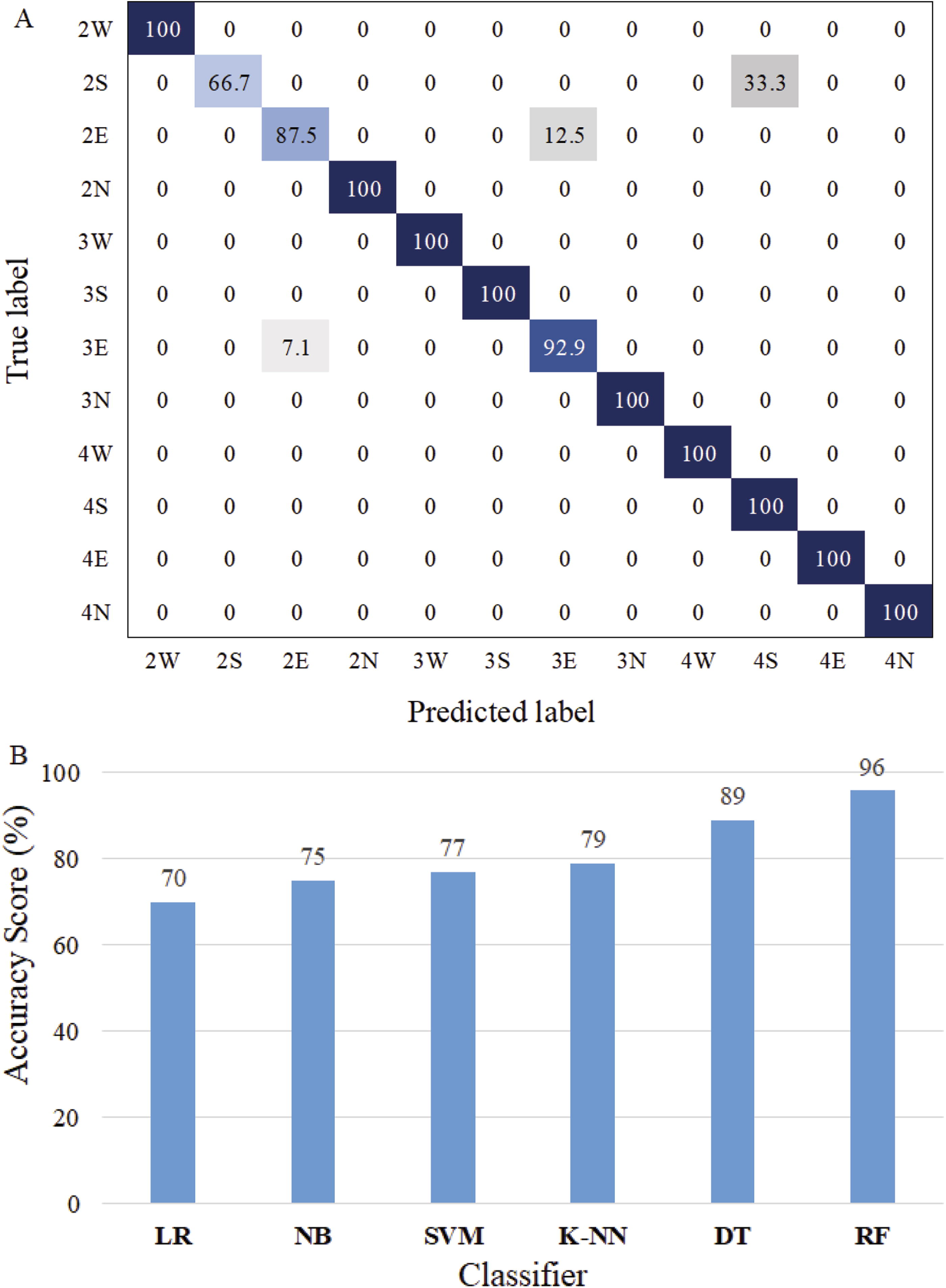
Various classifiers were evaluated during validation, including Logistic Regression, Naive Bayes, Support Vector Machine, K-Nearest Neighbors, Decision Tree, and Random Forest (RF). We selected RF Classification,31,32 because it achieved the highest validation score. The performance comparison of all tested classifiers and the confusion matrix from RF classification is shown in Figure 6B. The confusion matrix’s strong diagonal dominance indicates good classification accuracy.
Contacted robot pose and contact force estimation
Once the contact location and orientation are classified, regression is applied to estimate the disc-thread variable values used to reconstruct the robot’s pose and contact force. The regression process uses the same eight sensor signals as input variables. The output variables include 15 disc-thread values and the contact force.
The disc-thread model will capture general deformations for any soft robot that has some sort of longitudinal reinforcement, whether straight, helical or even with reinforcement segments that are disconnected radially. Fabric-reinforced inflatable soft robots that do not have unreinforced elastomeric sections like ours could still use this model if the reinforcement behaves such that on each disc/segment there is one location measured radially that is inextensible but the others can extend, such as when the fabric is pleated. In our case, the reinforcement is a single strip that lies along the longitudinal arc but this is by no means required. The RF classification method will fit the disc-thread model parameters to the IMU and photodiode signals, so for robots with different fabric reinforcement properties, all that would be required is a new training data set.
Results
Measurement and reconstruction of the soft robot in free space
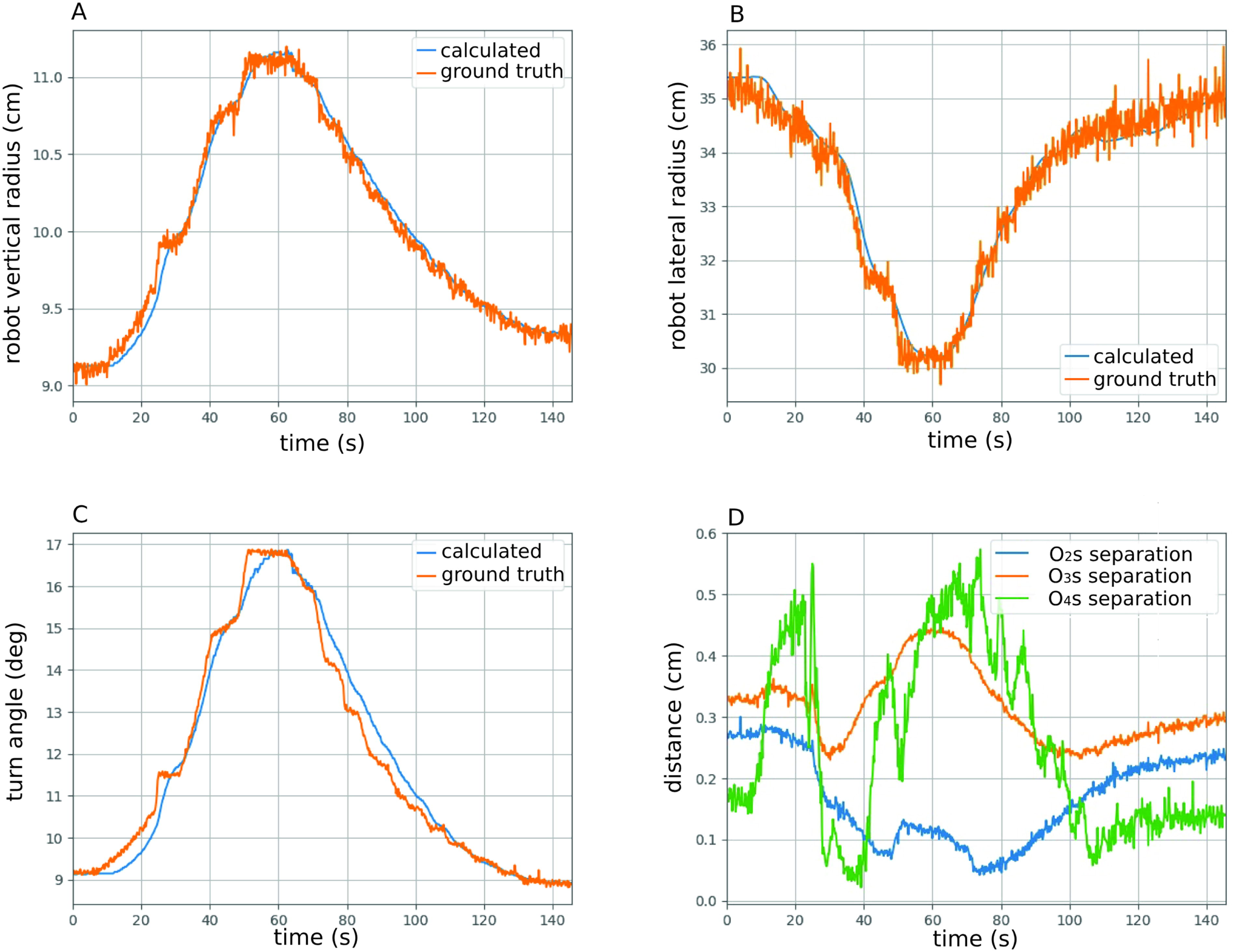
Figure 7 compares the poses identified from the IMU/light sensors (blue discs) with those determined directly from the Polhemus sensors (red discs). The poses align closely, with minimal error. Figure 8 tracks the SCS variables over time, including calculated radii and turn angles, which match well with the ground truth in Figure 8A–C, using selected coefficients

Calculated robot pose vs. the ground truth at different pressure values in free space.
The validation of the calculated pose compared to the ground truth during a motion cycle of the robot.
Reconstruction of the contacted soft robot
Figure 9 presents typical examples of contact localization and pose estimation, detailed in Table 1.

The matching between the estimated robot pose and the ground truth in six contact cases. The first row shows the contact experiment configuration. The second row shows the corresponding animated results. (A1-A2) Contact case 1; (B1-B2) Contact case 2; (C1-C2) Contact case 3; (D1-D2) Contact case 4; (E1-E2) Contact case 5; (F1-F2) Contact case 6.
Six Selected Contact Cases
The photos in the first row display the physical robot, while the animation frames in the second row illustrate the poses and contact force reconstructions produced by the trained model from the IMU/photocell combination. When we pushed on the robot and used the trained model (from RF) for the prediction, the contact localization accuracy was 96%, and the mean absolute error for pose estimation was 0.01. The classification algorithms accurately predict contact information, including position (disc number) and direction (indicated by the red arrow). For instance, in the first contact case (A1-A2), pushing the robot at disc 3 from the East direction (A1) resulted in a red arrow in the animation (A2) aligning with the load cell’s direction.
The algorithm’s pose estimates also match well. The animations show that contact poses estimated from pressure, IMU and photocell signals (blue circles) closely overlap with the ground truth (red circles). Average errors between disc centers, detailed in Table 2, are small (less than 1 cm) but increase for discs farther from the base.
Average Errors in Pose Estimations
Contact force estimation
Figure 10 shows the contact forces estimated from the trained model against the ground truth (load cell) in different six contact cases. It can be observed from Table 3. that the contact forces are closely estimated. The max average error (in case 4) is 0.454 N, which is satisfactory for a soft robot.

Comparison of estimated contact force vs. ground truth.
Average Errors in Force Estimations
Conclusion
This article introduces a new sensing strategy for soft inflatable robots using light variation within the chamber bore to track movement and contacts. The system integrates optical, IMU, pressure, and load cell signals for pose tracking in free space and contact force prediction. Contact is considered to have occurred when the robot’s pose deviates sharply from a simple curved arc model. Machine learning algorithms use contact data from various load and direction tests to accurately estimate pose, contact location, direction, and force. The pose measurement error in free space is under 0.35 cm, while in contact cases it is less than 0.9 cm, with 96% accurate contact localization. This approach eliminates the need for external measuring devices. Future work will focus on developing an adaptive controller to command motions in constrained environments and account for friction forces in the prediction.
Footnotes
Authors’ Contributions
P.D.H.B.: Conceptualization (lead); writing—original draft (lead); formal analysis (lead). J.A.S.: Methodology (lead), writing—review, and editing (equal).
Author Disclosure Statement
No competing financial interests exist.
Funding Information
This work is supported by the NSF grant No. 1935312 EFRI C3 SoRo: Between a Soft Robot and a Hard Place: Estimation and Control Algorithms that Exploit Soft Robots’ Unique Abilities.
a
This should not be confused with the physical fabric strip.