
Abstract
Amphibian taxa have adapted to thrive within demanding aquatic and terrestrial habitats. Leveraging their specialized anatomical features and distinctive modes of locomotion, amphibians present captivating paradigms for the emulation of bioinspired robotics. Robotics scholars exhibit profound interest in replicating their mechanisms. Nevertheless, the replication of amphibious motion necessitates produce automated actuation, which naturally powered by chemical energy converting mechanical energy process in animals. Prior research endeavors addressed this challenge through the development of rigid robotic systems employing integrated servomotors and intricate mechanical components, which limit the compliance of the robot design and complicate the robot control. In this study, we present research that bridges the remote magnetic robotics control approach and soft slime material to create a finger-tip-sized bioinspired magnetic soft robot (MSR), inspired by the mudskipper. This design has a simpler control method and an appearance more similar to the creature. The MSR with 3 cm length can recreate the terrestrial locomotion of a mudskipper under an ∼46 milliteslas (mT) single rotating external magnetic field. A singular row of space fabric structure was printed to serve as the robot’s pectoral fin by using a stereolithography additive printing technique. By emulating the rowing motion of the mudskipper’s pectoral fin structure, this design offers a locomotion model for estimating the stride length of robot’s movement, which contributes to refining the quantification approach for controlling slime-based MSRs such as conventional rigid robots. The untethered controllability, small size, predictable locomotion, and nonrigid body of the MSR show promising application potential in the biomedical engineering area.
Introduction
Soft robots have demonstrated potential for clinical applications due to their cost-effective fabrication methods, adaptable shape, multiple functional structure, and biocompatible compositions.1–4 Conventional actuations employed in soft robotics primarily consist of pneumatic and hydraulic control, offering a stable and wide range of output for robot operations.5,6 However, for interventional medical diagnosis and therapy scenario, soft robotics with such complex actuation systems, for example, catheter, can affect the navigation and locomotion of soft robots within the patient’s body. 7 Hence, remote control strategy is needed in interventional trials.
Magnetic soft robots (MSRs) have garnered attention across various research disciplines owing to their untethered controllability and remarkable environment compliance.8–11 They are constructed through the incorporation of magnetic components within the soft material carrier, which endows them with magnetic responsiveness.
Studies have demonstrated enhancements in MSR stretchability by testing various molecular structures of the materials, most of which exhibit notable viscoelasticity as slime.12,13 Recent research in this topic introduced a non-Newtonian borax-based MSR. 14 In this study, crosslink reaction-generated porous and flexible hydrogel molecular network facilitates the MSR deformation, which enhances the flexibility of borax-based slime and shows smooth locomotion. However, the viscoelasticity increases the morphological computation challenge because of deformation during the control. An inartificial macromolecular structure, cornstarch, has been used in a liquid–solid rapidly transformable MSR, 15 which alleviates the viscous deformation but dissolves in a water environment.
Although slime-based MSRs show viscoelastic properties and can be actuated for deformation, describing a predictable locomotion model for them is a challenge. The adhesion generated by the interaction between their viscoelastic structures and the locomotion interface contributes to the situation.16,17 Adhesion of slime-based MSRs cannot be avoided due to the robot body’s pressure on the substrate, which is mainly generated by gravity and magnetic attraction forces. Since the driving force of the MSRs are only provided by an external magnetic field, the passive manipulation nature makes it difficult to promote their movement through the interaction between its own structure and the contact surface.18,19 Employing modification methods to smooth the slime body and locomotion substrate has the potential to mitigate surface adhesion for these scenarios.
The passive locomotion exhibited by slime-based magnetic robots poses challenges in determining the locomotion stride length, making the robots unable to be manipulated precisely. Amphibious organisms possess distinctive physiological structures such as robust legs, fins, and tails, enabling them to thrive in both aquatic and terrestrial environments through positive locomotion mechanisms. Besides, terrestrial movements of amphibious organisms are typically coordinated and rhythmic, which has a calculable stride length. Nevertheless, these movements are normally powered by chemical energy-converted mechanical energy. For artificial robotics imitation, researchers have designed mechanical structures to mimic the animals’ bodies and actuate the robots with electrical and mechanical power sources.20,21 However, robots controlled by these power sources cannot minimize the size to clinical intervention application standard and the complex power sources prevent them from remote manipulation. In this work, we studied the locomotion methods for a slime-based MSR from an amphibious fish called mudskipper that has a soft body and strong pectoral fin. A magnetic mudskipper robot (MMR) was presented for enabling slime-based MSR with a predictable locomotion stride length. To enable the robot to move coherently in an amphibious environment, a material with impressive water absorption capacity was selected as the soft body. Modification methods for material and locomotion substrate were utilized to diminish the robot’s surface adhesion and augment locomotion robustness. The rheologic factors were tested for proving the material modification results. An artificial 3D printing pectoral fin has been designed to mimic the actions of mudskipper during their movement on mud surfaces. Rowing action of this fin structure was proved by remote magnetic control. This artificial pectoral fin facilitated smoother movement of the slime body on terrestrial substrates. By assembling this mechanical structure, the stride length of the locomotion can be introduced to enhance the accuracy of locomotion for targeted treatment and drug delivery. The magnetic response hysteresis was discussed in the magnetic controlled terrestrial locomotion experiment section to study the relationship between the external magnetic field and the robot’s stride length.
Materials and Methods
The MMR consists of two components: an artificial pectoral fin and a slime body. Stereolithography 3D printing technique was utilized for fabricating MMR’s artificial pectoral fin. 3D printer (Formlabs) was employed for fin printing. To enable magnetic control, two cylinder magnets (2 mm thick × 2 mm diameter) were individually inserted into the tips of pectoral fin, oriented with the same pole direction. The slime body of a robot was fabricated by mixing wheat gluten powder with oil, fine iron powder and water and then shaped by a mold. The robot body and artificial fin were assembled manually to emulate the mudskipper.
A magnetic control platform was constructed in a 20 × 20 cm2 area, utilizing a 6-mm-thick acrylic board. Rotating external magnetic fields were produced by rotating a series of permanent rectangle magnets.
In situ magnetic attraction test was accomplished for proving the slime coherent locomotion challenge caused by viscous deformation qualitatively. Three slimes (gluten-based slime, cornstarch-based slime, and magnetic putty slime) were individually set on the surface of control platform for recording the slime body change. Through moving a constant size permanent magnet (∼350 mT) beneath the slimes, the magnetic attraction force was adjusted. The interaction between slime and magnet was recorded while the slime started to deform. The mass of each slime was 4 g.
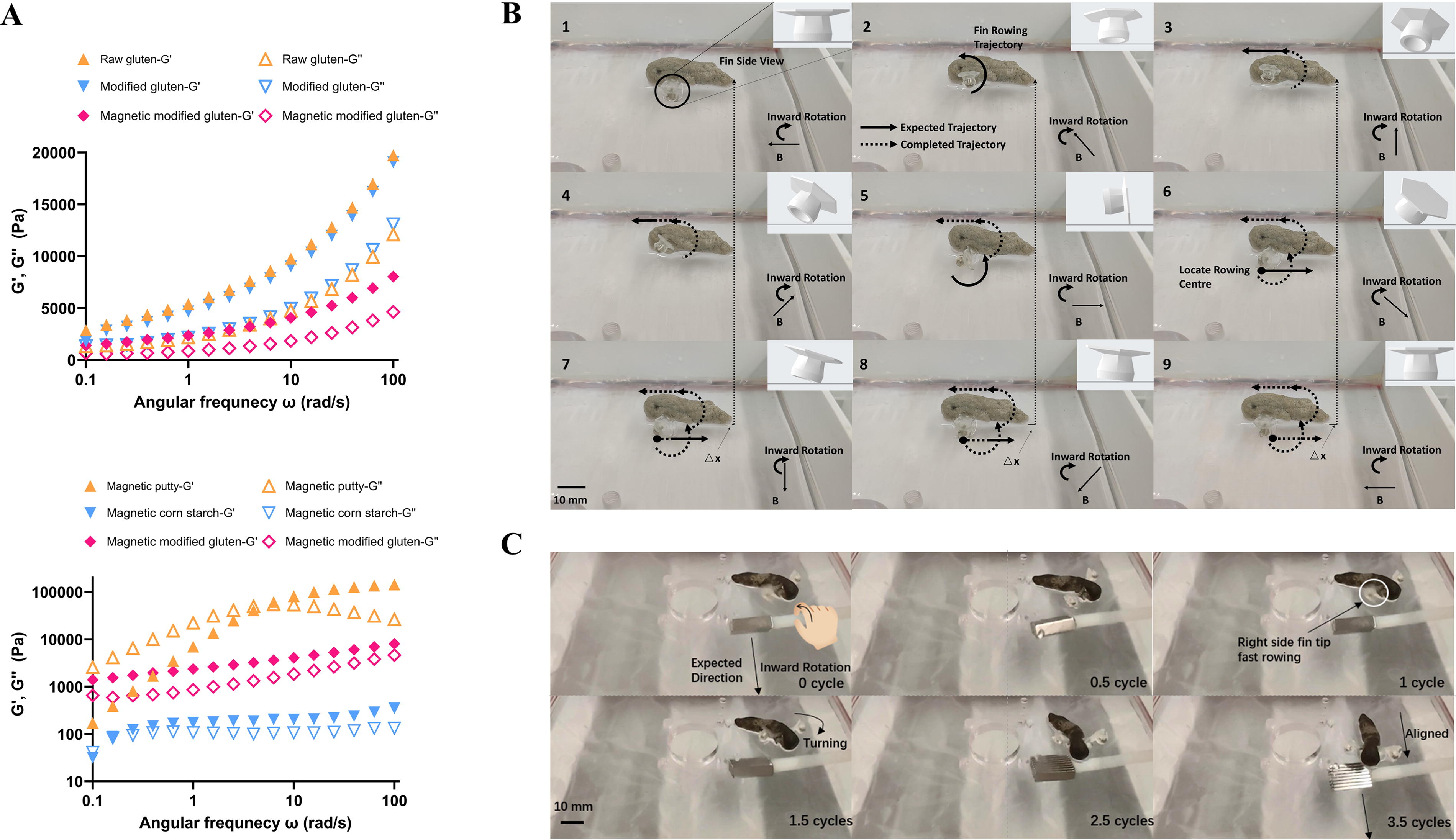
Slimes were characterized by rheometer test for getting the rheologic data. Magnetic putty slime (First4Magnets Ltd, UK) was a commercial product. Gluten-based slime was made by mixing wheat gluten flour (BWFO Ltd, UK), iron powder (First4Magnets Ltd), water, and 3–5drops of cooking oil, stirring the composite for 30 seconds and kneading evenly for a few minutes (1 wheat gluten: 1 water: x iron powder [in mass ratio, x depends on MMR iron particle proportion]). Cornstarch-based slime was made by mixing cornstarch (Interlink Direct Ltd, UK), iron powder (First4Magnets Ltd), and water and stirring the composite for 5 minutes (6 cornstarch: 5 water: 5 iron powder [in mass ratio]). 15 All these slimes were tested in a rheometer (TA instrument, DHR-3 rheometer). Oscillation frequency procedure was chosen to get the storage modulus and loss modulus of these slimes. Temperature was set at 22°C, and angular frequency was from 0.1 to 100 rad/s, 5 points per decade. A 20 mm parallel plate, Peltier steel plate, was chosen as the geometry and the working gap is 1000 μm.
MMR was tested for proving amphibious locomotion ability in the control platform. Three centimeter MMRs with 2.5-cm-long artificial pectoral fins were tested for all terrestrial linear locomotion. The rotating magnetic field was produced by a pistol drill with fixed permanent magnets in the tip and beneath the control platform. Turning control was tested by rotating a fixed permanent magnet that taped in tip of the plastic rod with 1A working current motor. The rotating direction was inward from the MMR head view. The electromagnetic (EM) tracking system (Aurora, NDI Medical, Canada) played an MMR displacement monitor role.
A 24 L PVC plastic box with a 6-cm-deep water environment was applied for ultrasound imaging tracking. MicrUs and MicrUs Pro Series Ultrasound Systems were employed as the ultrasound imaging tools. Echo Wave II software was applied to set up the parameters for ultrasound imaging and output MMR locomotion results. To trace the MMR movement, a metal needle was settled in the water as a reference line.
A mechanical test was done to get a biocompatible material parameter for artificial pectoral fin rowing simulation. Instron 5967 mechanical tester was selected with ASTM D412(Method A) tensile testing according to the elastic 50A resin vendor information. The resin was printed with the same print direction of artificial pectoral fin on a “dumbbell” shape. Thickness of the specimen was measured three times, with the median value being the accepted value. A 10 kN load cell and a 5 kN gripper were used for the mechanical test. The test was at a rate of 200 mm/min until the specimen fails and the strain–stress results were obtained.
COMSOL software was utilized to calculate the magnetic forces acting on each section of the artificial pectoral fin during its one rowing cycle. Gravity was excluded from the simulation.
ANSYS software was used for finite element analysis for artificial pectoral fin deformation. The mechanical parameters of elastic 50A resin were employed to establish engineering data in this scenario. The magnetic force data from COMSOL software were input to get the artificial pectoral fin deformation status.
Results
Bioinspired creature
Mudskippers, smart amphibious fish, can move on a terrestrial surface through the pectoral fins’ “crutching.” 22 The crutching of the pectoral fins exhibits robust behavior to help the body move forward and the moist and soft body enables them to move smoothly in the mud (Fig. 1A). They achieve propulsion and maneuverability by modulating the shape and angle of their pectoral fins. 23 The pectoral fins can generate propulsion forces by leveraging the positioned initiated stride point at the tips of the pectoral fins, thereby propelling the fish forward or altering its direction.24,25

Amphibian-inspired magnetic soft robot design.
Artificial pectoral fin
Slime-based MSRs were fabricated more adaptable for movement by incorporating functional unit, which produced more propulsion than the slime-based MSR structure can offer alone. Using an artificial structure to emulate mudskipper’s pectoral fins is the strategy in this study (Fig. 1A). The pectoral fin of a mudskipper has a hinge-like adaptable joint structure that can lift the mudskipper’s center of mass and promote terrestrial movement. 26 NASA chainmail space fabric, characterized by mechanical anisotropy in the bending direction, 27 was selected for modification as an artificial fin structure for the MMR. However, MMR in this work cannot properly accomplish crutching because the slime center of mass is difficult to lift by solely magnetic field repulsion. Therefore, this work denoted the motion of the artificial pectoral fin as “rowing,” 28 highlighting the shift process between rigid and flexible directions within the fin structure (Fig. 1A). Hexagon space fabric has a mesh lattice structure, each intersection of the lattice forms a small ring structure.29,30 The ring structure can be perceived as a form of binder yarn in space fabric, serving to secure and link lattice units (Fig. 1B). The ring structure provides flexibility in one direction, enabling the fabric to adapt to different shapes and surfaces. Conversely, in the opposite direction, due to the interaction among lattice units, the fabric exhibits greater rigidity and strength, imparting protection and support capabilities (Fig. 1B). Space fabric structure can be fabricated by 3D printing with both tough and soft material at a low cost. Interestingly, the rigid–flexible direction mechanism can be reversed when we print a singular row of space fabric structures with soft material and remove some ring structures (Fig. 1B). This change provided an opportunity to aid the end lattice unit in identifying a center for rowing through compressive interactions and structure twisting. Hence, a singular row of elastic space fabric structures was selected as the pectoral fin of the MMR (Fig. 1B). The length of the fin is at a minimum of 25 mm due to the inserted magnet size restriction in this work (2-mm-thick* 2-mm-diameter cylinder). In the flexible direction, elastic deformation aids the robot adjusting its body and locating the subsequent rowing center. Conversely, in the rigid direction, it furnishes a fresh rowing center for the robot’s subsequent movement. The continuous alternation between rigid and flexible directions produces the robot’s continuous motion and offers a potential measurable stride length for enhancing control accuracy. This movement mechanism resembles the terrestrial motion of the pectoral fins of the mudskipper 31 (Supplementary Video SV1), featuring propulsive phase and recovery phase. 22 Such a mechanism can facilitate a robot body to move on the surface rhythmically (Fig. 1C). With an embedded ordered array of magnets, this structure is capable of executing backward and forward rowing motions when subjected to a rotating external magnetic field, while the middle ring structures can drive the MMR body to move forward. This amphibian-inspired locomotion mechanism is also promising as a breakthrough in overcoming the slime-based MSR passive locomotion challenge.
Modification on slime body materials
Reducing surface adhesion can enhance the locomotion flexibility of the slime (MMR body) component. This adjustment enables the robot to move smoothly when situated in damp terrestrial substrate. Such enhancement can be achieved by modifying the slime materials with lubricants, such as cooking oil.32,33 Meanwhile, the in situ viscous deformation generates locomotion hysteresis, such as material elongation. The adhesion between the MSR slime body and the substrate lowers locomotion flexibility, a challenge that has to be overcome. The putty-based MSR showed significantly different locomotion styles on dry versus oil-coated acrylic substrates. On a dry substrate, the MSR surface adhesion resulted in the back half of its body being held in place while the front half was elongated by external magnetic attraction to 109%. Conversely, on an oil-coated substrate, the oil reduced the putty-based MSR adhesion on the substrate, subsequently enhancing its locomotion speed significantly (Supplementary Fig. S1 and Supplementary Table. S1). This challenge can also be mitigated by enhancing the elasticity of slime-based MSRs. Gluten, an edible slime material, was selected as the MMR body due to its distinctive protein macromolecular structure. Compared with putty and cornstarch, wheat gluten shows less deformation hysteresis due to both its relative elastic and viscous structure, generated by the interaction between gluten molecules and water, which can enhance locomotion efficiency with more coherent movement. Its porous structure contains abundant hydrogen bonds, which results in remarkable water absorption properties. The absorption ability enables the robot to maintain a soft structure while the surface is modified. To prove the strategy’s feasibility, we tested the locomotion among putty-based, cornstarch-based, and modified gluten-based slime materials through in situ magnetic attraction tests. Under an approximately 350 mT magnetic field, cornstarch-based magnetic slime exhibited 78.9% portrait elongation, respectively, and no shape recovery. Putty-based magnetic slime showed 25% horizontal swell and slow portrait shape recovery. Conversely, modified gluten-based magnetic slime maintained the lowest shape deformation and fastest shape recovery time (Supplementary Table S1). The rheometer test results showed that the modified gluten has a smaller gap between the storage modulus and the loss modulus than the raw gluten material. When coated with magnetic particles, this gap was further reduced (Fig. 2A). This can explain the reason for modified-gluten-based MSR’s good shape recovery ability. A comparative analysis of storage modulus and loss modulus across magnetic putty, magnetic cornstarch, and magnetic modified gluten reveals that magnetic modified gluten experiences fewer viscoelastic interactions between molecules than magnetic putty. This characteristic enables the magnetic modified gluten to deform–recover more rapidly than magnetic putty. At the same time, the magnetic modified gluten can survive in water and has better deformation resistance than magnetic cornstarch (Fig. 2A). Hence, the modified gluten was considered emulating the moist body of a mudskipper.
MMR’s slime body characterizations and locomotion tests.
Terrestrial locomotion for MMR
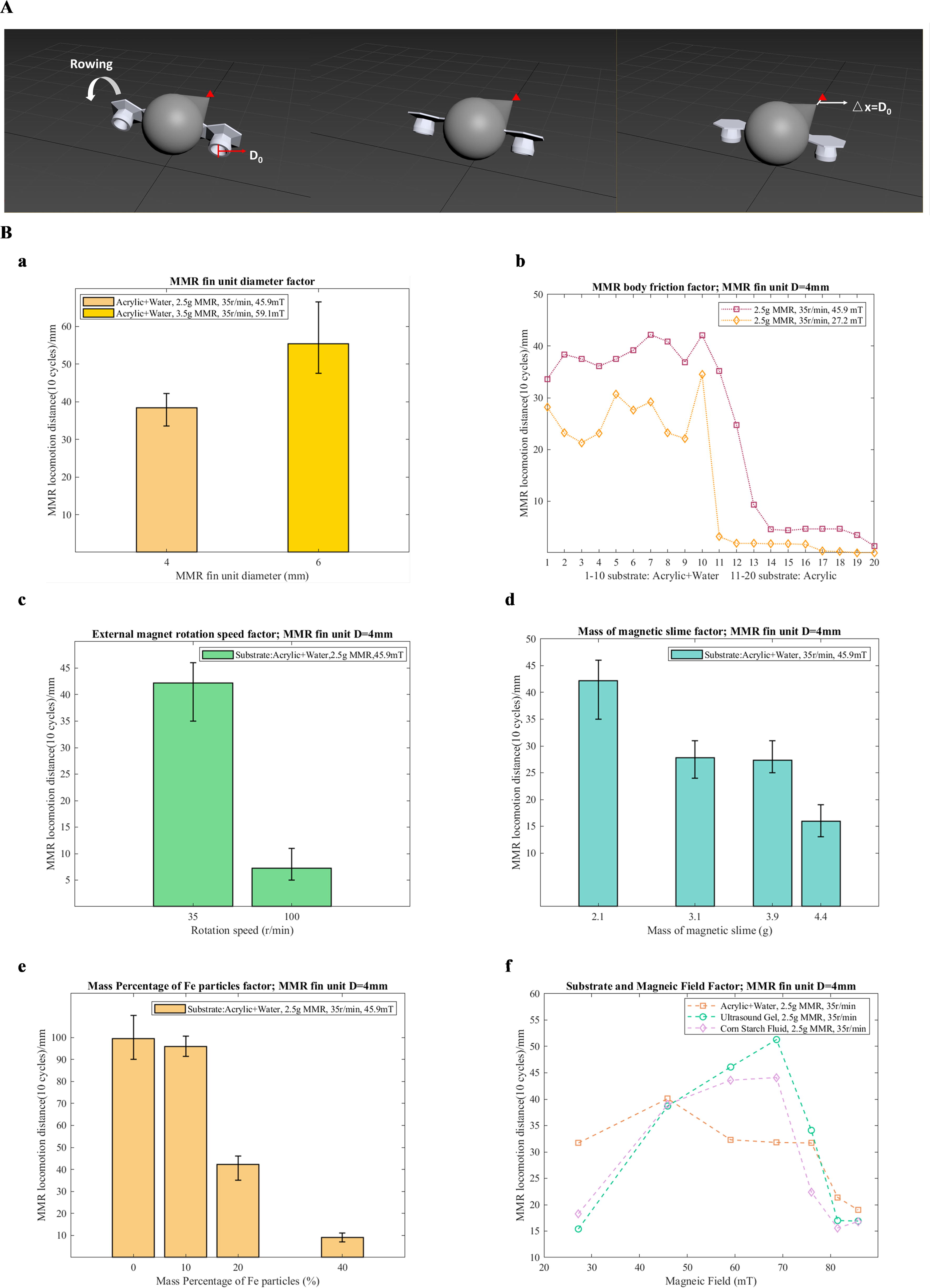
The MMR was tested in a laboratory-created damp terrestrial substrate (acrylic plane spread with a layer of water) first. The results demonstrated that the robot’s linear motion can be controlled though an external rotating magnetic field, generated by a singular rotating permanent magnet. The interactions between driven parts in the fin and external magnetic field induce the rowing motion of the artificial pectoral fin. During one magnetic field rotation cycle, the artificial pectoral fin performed the rowing cycle, as shown in Figure 1C (Fig. 2B and Supplementary Table S2). When the driven parts were attracted by an external magnetic field, the fin contracted forward, creating a propulsion tendency for the robot. During half of the rotation cycle, the fin underwent backward rowing motion, transitioning from being fixed at a rowing center to completing one stride movement (Fig. 2B, 6–9). Subsequently, as the external magnetic field repelled the driven components in the subsequent half of the driving magnet’s rotation cycle, the fin pivoted backward while being rowed forward and adjusted the orientation of the fin tips to locate the next rowing center (Fig. 2B, 1–5). Notably, this adjustment occurred in situ, as the fin tips remain detached from the substrate. Through continuous alternation between these two states, the MMR was propelled forward. Directional turning occurred when magnetic field asymmetry influenced both sides of the fin. One side of the fin cycled through these two states more rapidly, while the slime body was subjected to changes in locomotion direction induced by variations in the external magnetic field, causing it to bend (Fig. 2C, Supplementary Video SV2, and Supplementary Table S2). Through varying the diameter of the artificial pectoral fin unit, the stride length can be alternated. The mechanism for calculating ideal MMR locomotion stride length is illustrated in Figure 3A and Supplementary Video SV3. The initial status is defined as the rowing center where the artificial pectoral fin is located (Fig. 2B, 6). Through half of the rotating magnetic field actuation, the fin comes into contact with the substrate and advances the MMR body forward. Hence, the ideal stride length can be defined as the diameter of the artificial pectoral fin unit. The ideal locomotion displacement S can be calculated by the following equation:
MMR’s amphibious locomotion stride length experiments.
where n is the rowing cycle of artificial pectoral fin and D0 is the diameter of the artificial pectoral fin unit.
We tested MMRs with differing fin unit diameters, and the MMR with a 4-mm fin unit diameter exhibited more accurate stride length measurability while approaching the ideal stride length (Fig. 3B-a and Supplementary Table S2). The artificial fin cannot produce enough force to propel the MMR forward in a two times larger rotating magnet in a volume of a 4-mm-diameter MMR test when the diameter was extended to 8 mm (Supplementary Table S2). The reason being that the size of each artificial fin unit is too large to complete a full rowing cycle by actuating the selected inserted magnet. In the linear locomotion test (4-mm-diameter fin unit), we found magnetic response hysteresis, which resulted in each magnetic field rotation not generating an ideal stride length (Fig. 3B-b and Supplementary Table S2). When the magnitude of the external magnetic field was increased, the magnetic hysteresis response decreased and approached the ideal value. Interestingly, after completing 10 locomotion tests in an acrylic plane covered by a layer of water, we settled the moist MMR onto the dry acrylic plane and tested its locomotion 10 times, the displacement of MMR declined instantly (Fig. 3B-b). This result indicates that the MMR is still affected by high adhesion once it leaves the damp terrestrial environment, which is similar to the mudskipper locomotion challenge without moist mud and skin.
To further investigate the magnetic response hysteresis, we used the external magnetic field with 100 rpm rotation speed to induce fin rowing, enhancing the hysteresis. Hence, we compared the MMR control with two different external magnetic field rotation speeds; the results indicated that if the rotation speed exceeded the magnetic response, the MMR locomotion hysteresis will significantly increase and the MMR locomotion displacement will decrease (Fig. 3B-c). The pressure caused by slime body is another factor that can affect the MMR locomotion performance. As the mass of slime body increases, the displacement of MMR in 10 cycles rowing declined, respectively (Fig. 3B-d). The results indicated the gravity slime body contributes to the pressure. Besides, the pressure was also relative to the magnetic particle proportion of slime body because the magnetic parts enable the slime body to be attracted by an external magnetic field. When the slime bodies with few magnetic particles were actuated, the MMR locomotion displacements were not relative to the fin unit diameter because the MMR pressure cannot balance the horizontal magnetic attract force. While controlling the slime body with excess magnetic particles (40% in slime body mass), the pressure prevented the MMR moving forward (Fig. 3B-e). For this MMR design, a 20% magnetic particle proportion performed well and the MMR locomotion displacement was relative to the fin unit diameter. To test the feasibility of MMR locomotion in different substrates, two mud-like substrates, ultrasound gel and cornstarch fluid, were utilized for this work. The parameter of MMR was determined according to the above experimental results; various external magnetic fields were applied to control the MMR. Under 45.9 mT magnetic field, MMR locomotion displacements were relative to the fin unit diameter in all the substrates. With the magnetic field increase, MMR locomotion displacements in ultrasound gel and cornstarch fluid went up first and declined when the magnetic field exceeded 70 mT. However, the MMR locomotion displacements in damp acrylic substrate decreased when the magnetic field exceeded 50 mT (Fig. 3B-f). A reasonable explanation is that the pressure contributed by magnetic particles loaded on the substrate has a different scenario. For damp acrylic substrate, the pressure of MMR can directly act on the contact surface. However, the pressure of MMR cannot throughout be applied on the layer of ultrasound gel and cornstarch fluid. In addition, since the latter substrates are fluids, the surface slide will also increase the MMR displacement.
Kinematic study for MMR fin rowing
Singular fin (2.5 cm) and 3 cm MMR with fin (2.5 cm) were tested for getting the mean kinematic profile of one rowing cycle. The reference point is point 1 at fin tip in Figure 1C and the fin tip’s location is on y-axis, which is the MMR locomotion direction (Fig. 4A-a). Without slime body assembly, the flexibility and rigidity alternation of the pectoral fin structure was unrestricted. Since the slime body was joined to the pectoral fin structure, the flexibility and rigidity alternation were affected and displayed the above pectoral fin rowing mechanism, as shown in Figure 1C and Figure 2B, the fin rowing (0%−50%) was the propulsive phase of MMR. The fin tip’s location went up and back to zero in 0%−25% fin rowing stage because the fin at this stage had no contact with the substrate and the fin was dragged by the external magnetic field. Hence, the fin twisted and swinged before it located the rowing center. The rowing stage (25%−37.5%) was the process of fin rowing around the rowing center. From a theoretical analysis (Fig. 4A-b), the fin tip displacement during the process of fin rowing around the rowing center can be expressed as follows:

MMR’s amphibious locomotion mechanism and simulations.
where
The static rowing status for MMR was recreated by simulation analysis to study the recovery phase of the pectoral fin (50%−100%). At the initial forward rowing stage, the magnetic force applied at the tip of artificial pectoral fin makes the structure twist and generates a forward rowing tendency according to the finite element analysis results (Fig. 4C and Supplementary Table S2). During the recovery phase, the fin tip’s location went negative and back to zero for beginning the next round of rowing. The calculable millimeter-range stride length shows the potential that it can stop in each tiny interval area to undertake special tasks.
Specific locomotion for MMR
To assess the applicability of the robot in interventional therapy scenarios, its locomotion within a stomach phantom was investigated (Fig. 5A, Supplementary Video SV4, and Supplementary Table S2). A wrinkled and damp surface was employed to play the role of stomach wall surface, and the MMR achieved ∼4 mm stride length locomotion in each rowing cycle with 41.5 mT magnetic field manipulation. The results demonstrated that the MMR has potential to be applied for interventional therapy. However, the propulsion force and rowing robustness have to be further improved through advanced fin structure and magnetic control to ensure stride length accuracy in uneven substrates.

MMR’s amphibious locomotion application scenarios in laboratory.
Ultrasound imaging guidance was employed for testing the remote image guiding feasibility for MMR. Under ultrasound scanner tracking, the rowing motion of the 4-mm-diameter MMR’s artificial fin can be seen in the image results. When the MMR’s pectoral fin made contact with the substrate, the ultrasound image of the MMR showed a lifting off of the MMR tail end from the substrate. The rowing of the fin resulted in this interaction between the MMR pectoral fin and the substrate, which generated the propulsion of the MMR movement. The momentary lift can be considered a buoyancy and net surface adhesion lead result when the artificial pectoral fin rows around the rowing center, which does not happen in terrestrial locomotion. This lift phenomenon in water locomotion hindered the MMR rowing progress. However, the buoyancy vanished the surface adhesion from MMR body pressure, resulting in an 18 mm locomotion distance in 10 rowing cycles with 35.6 mT magnetic field manipulation (Fig. 5B and Supplementary Table S2). Besides, the result also demonstrated that the MMR terrestrial locomotion is not only passively attracted.
Discussion
This study centered on emulating the pectoral fins, which serve as the primary propulsive component of a mudskipper, by utilizing soft materials, thereby enabling the bionic MMR, no longer a skeleton or joint mechanical structure. The appearance and locomotion of the MMR closely resembled those observed in real mudskippers. This design achieved the animal’s natural locomotion through a straightforward magnetic control strategy without a complex control system and mechanical design, which is energy-efficient and environmentally friendly.
A bioinspired strategy was presented to overcome current passive locomotion challenges for high viscoelastic slime-based MSRs. Unlike another bioinspired soft robot from worm, which can be fabricated by an elastomer material to recreate the locomotion stride precisely,34,35 the viscoelastic slime materials perform morphosis transformations and are passively controlled with a singular magnet. They display multiple locomotion styles, including roll, slip, and curl, which cannot be used to quantify the locomotion’s stride length.14,15,36 Through designing an artificial pectoral fin structure to replicate a mudskipper’s terrestrial motion for our MMR, a locomotion model with calculable stride length was established. MMR demonstrated a step length that was closest to the theory on acrylic board. Nevertheless, on flexible substrates such as a rubber glove and in a water tank, incomplete rowing resulted in a step length that significantly deviated from the theoretical value. This needs to be further solved in future work if MMR will be promoted for medical application. Besides, the artificial fin structure also generated positive locomotion avoiding the phenomenon of hyperpressure on the locomotion interface, which affects solely passive attraction locomotion models.
By incorporating a lower viscoelastic gluten material and a modification method to mimic the moisture and smooth skin of the mudskipper, the adhesion between the locomotion interface and robot body was reduced. Gluten-based slime material exhibited robust environmental compliance especially in water, something the cornstarch could not achieve. However, our design currently is not suitable for the locomotion interface without a water coating, the adhesion between the slime body and dry substrates cannot be fully overcome by the current strategy. Future works for resolving this challenge include applying lower adhesion materials and iterating the pectoral fin design to achieve the crutching locomotion method, which can enhance the contact robustness between the artificial pectoral fin and substrate. However, in this work, the adhesion interactions between different interfaces were not further studied. The in situ magnetic attraction test can only provide qualitative results to guide the locomotion interface selection.
Slime-based MSR locomotion currently cannot be illustrated by a mathematical simulation model such as continuum soft robots because the deformation of slime-based MSRs is irregular, while shaped artificial pectoral fin insertion for fast body shape recovery MMR can transfer the irregular viscoelastic slime body into a consistent body. COMSOL simulation was selected to calculate the magnetic force of the inserted magnet at each rowing section. We built up a simulation for the artificial pectoral fin’s deformation process in ANSYS software; the results recreated the status of rowing.
The adjustable size and untethered magnetic manipulation of magnetic slime make them suitable for interventional robotic applications. However, medical equipment hazards can be lethal for patients, which raises ethical and legal concerns for hospitals and patients. Magnetic putty fabricated with boric acid is hazardous for patients, which makes it unsuitable for human test subjects. Food-based slime, such as cornstarch and gluten, is edible for humans, making them a prime research material to develop interventional soft magnetic robots. Besides, robot survival in the human body environment is a key step in making them functional in clinical scenarios. Currently, the gluten-based MSR shows better robustness than the cornstarch-based MSR in liquid environments. However, gluten can still be dissolved in a stomach acid environment and is not suitable for celiac patients. A gastric acid resistance test is needed. For future potential clinical tests, the force analysis for MMR fin rowing on the organ–robot interface needs to be further discussed to ensure that the MMR locomotion will not damage the internal organs.
Conclusion
In this study, an amphibian-inspired strategy was utilized for MMR design and fabrication, which provided calculable locomotion stride length in millimeter scale. The coherent locomotion provided the MMR to adapt to specific tasks in an energy-saving way promisingly. We demonstrated the idea through a series of experiments, including material characterization, magnetic control locomotion, and proposed a kinematic model to explain the robot working schematic. In comparison with literature on mudskipper observation, our MMR’s locomotion schematic closely resembles that of the actual creature. The parameters that affect the MMR locomotion distance were studied and a steady control method was determined with proper external magnetic field rotation speed, robot mass, robot composition, and the magnitude of external magnetic field. By combing the medical imaging technologies, the MMR showed promising application potential in the biomedical engineering area.
Footnotes
Authors’ Contributions
L.N. designed and fabricated the robot, carried out the experiments, developed the robot locomotion model, processed the data, and wrote the article. C.L. and Z.T. contributed to scientific discussion and experiment design. L.N. and C.L. worked on simulation. Z.T. supervised the project.
Data and Materials Availability
All data needed to evaluate the conclusions in the article are present in the article and/or the supplementary materials. Additional data related to this article may be requested from the authors.
Author Disclosure Statement
The authors declare that they have no competing interests.
Funding Information
This study was supported, in part, by the
Abbreviations Used
References
Supplementary Material
Please find the following supplemental material available below.
For Open Access articles published under a Creative Commons License, all supplemental material carries the same license as the article it is associated with.
For non-Open Access articles published, all supplemental material carries a non-exclusive license, and permission requests for re-use of supplemental material or any part of supplemental material shall be sent directly to the copyright owner as specified in the copyright notice associated with the article.