
Abstract
The use of fluidics in soft devices has gained popularity in recent years, particularly in actuators and logic circuits. However, most tactile pressure sensors in the literature output an electrical or optical signal increasing the complexity of soft devices as the electrical or optical signals are transduced from the sensors to fluidic logic, and electrical power is needed just for the purposes of sensors and transducers. Including electrical and optical materials into a soft device also complicates the fabrication of the device. To address these drawbacks, we propose a soft pneumatic tactile pressure sensor matrix consisting of four sensors and operating on fluidic principles. Each sensor contains a meandering microchannel fabricated only from the same elastomer typically used in soft devices. When compressed, the pressure drop of the channel changes, which is measured as a sensor output signal. Our sensors can detect forces ranging from under 0.1 N to 4 N, with a maximum sensitivity of 50.5 N−1. They have a hysteresis of 3.9% and the sensor signal drifts 16.4% in 12 hours under static compression. By using multiple sensors in a matrix, we can detect the point of contact and the magnitude of the applied force. Furthermore, we demonstrate that by attaching a protruding post to the matrix, we can infer forces acting on the post in three axes. This work paves the way toward electronics-free, entirely fluidic soft devices and soft robots that can detect not only the magnitudes of the contact forces but also their locations.
Introduction
In soft devices and soft robots, many functionalities have been realized using entirely fluidic components that use fluidic pressures and flows to transmit information and energy.1–5 This is in stark contrast with more conventional components, which use electricity or light for the same purpose. For soft devices, the advantage of using fluids is their inherent deformability. In addition, fluidic channels can be fabricated in soft elastomers that, at least in bulk, can tolerate up to 1000% elongation before breaking.
Fluidics has been proven particularly advantageous for soft devices, especially for soft fluidic actuators.2,6–8 Soft fluidic actuators are driven by compressed gases or liquids and are capable of producing large deformations. A variety of motions such as bending, twisting, and contracting have been demonstrated.7,9–13 Soft fluidic actuators can produce significant forces reasonably fast, e.g., 1.4 N force within 130 ms for an actuation pressure of 72 kPa. 7 However, in many of the examples in the literature, the fluidic actuators have been used without any sensors, operated completely in open loop,2,14,15 or based on camera feedback. 16 If the actuators of the soft device are fluidic, and the sensors are based on other energy domains, the mismatch of the included energy domains leads to a need for transducers, increasing the complexity of the device. Fluidic sensors that operate on similar fluidic principles as the actuators would simplify the overall device.
Tactile pressure sensors measure the contact forces and pressures applied on the sensor surface. Such sensors can be used in soft devices and soft robots to perceive the surrounding environment by giving them the ability to gather information about the shape, smoothness, toughness, and temperature of the objects they encounter.17,18 This information is critical for soft robots to pick up delicate objects without breaking them,19,20 to sense the surface texture of manipulated objects, 21 and to notice and avoid collisions with objects or people minimizing the risk of injury or damage.17,22 In addition, tactile pressure sensors are used in haptic user interfaces to detect the forces applied by the human finger on the input device. The advantages of soft materials in such user interfaces include the ability to deform the input device to, e.g., create virtual buttons 23 and the general comfortability of using soft user interfaces.24,25
Soft tactile pressure sensors based on various transduction phenomena have been proposed, including capacitive,26–29 resistive,30–33 and optical sensors.21,34 Sensors that can be stretched to elongations of 100% or more have been reported.21,32 Stretchable optical waveguides operate by detecting changes in the optical signal between a light emitter and photosensor. Compressive force on the waveguide causes deformation of a light guide that is embedded inside elastomeric material, leading to a change in the path of the guided light which is detected and transduced into the electrical output signal. 21 Some optical sensors measure the attenuation or reflection of light varying based on the deformation of the target object. 34 In capacitive and resistive sensors, conductive sensing elements typically including metallic or carbon-based fillers (e.g., nanowires, -particles, or -flakes) are patterned inside inherently soft, elastomeric materials.35–37 Since conductive materials are usually rigid in bulk, these sensing elements need to balance between adequate conductivity and stretchability. 6 To overcome this trade-off, stretchable electric tactile sensors have been fabricated from elastomeric microchannels filled with a liquid conductor (e.g., gallium-containing alloys such as eutectic gallium—indium, EGaIn) or ionic liquids.30,32,38 The electric resistance or the capacitance of the sensing element changes in response to compressive force. However, less attention has been given to tactile pressure sensors that operate based on fluidic transduction phenomena. Of the few reports25,39–44 of fluidic sensors in the literature, most works are based on measuring the pressure change in a soft chamber owing to deformation, where the volume change is directly related to the pressure according to Boyle’s law.25,39,40,43
In our previous work, 44 we proposed a pneumatic strain gauge that outputs a fluid pressure signal. The sensor works on the principle of measuring the pressure drop in an elastomeric microfluidic channel through which air flows. This separates our fluidic sensors from the works reporting sensors based on Boyle’s law,25,39,40,43 as our sensors have a continuous flow through the channel at all times. As the microchannel of the strain gauge is elongated, its geometry changes. Consequently, its fluidic resistance changes, which results in a change in the pressure drop over the channel. We demonstrated that such sensors can be integrated into the fingers of a soft and fully pneumatic gripper, endowing the gripper with perception. Based on the sensor signal from pneumatic sensors integrated into its fingers, the gripper was able to infer the shape of the objects it picked. However, with a single sensor per finger, the sensors did not offer any precise information about the point of the applied compression along the finger.
Ideally, the sensors should be able to obtain multichannel information, from which not only the intensity of the forces acting on the sensor surface can be inferred but also its location. For a soft robot, this means that a single sensor per actuator or finger is not sufficient but multiple different sensors should be distributed across the surface of the robot, providing information about the shape, texture, and other physical properties of the environment with which the robot is interacting. Similarly, rehabilitation devices and wearable monitoring systems45–47 require multiple sensors over the surface area of the device, e.g., to locate a finger pressing a wearable electronic skin. 48 Choi et al. 42 reported a pneumatic sensor matrix with three row sensors and three column sensors and used a neural network to estimate the contact location in a 3-by-3 grid. The network outputted a discrete classification which of the nine matrix points was being compressed, with a classification accuracy of 87.3%. Each grid point corresponded roughly to an area with a side length of 16 mm, so the contact location could be estimated only very coarsely.
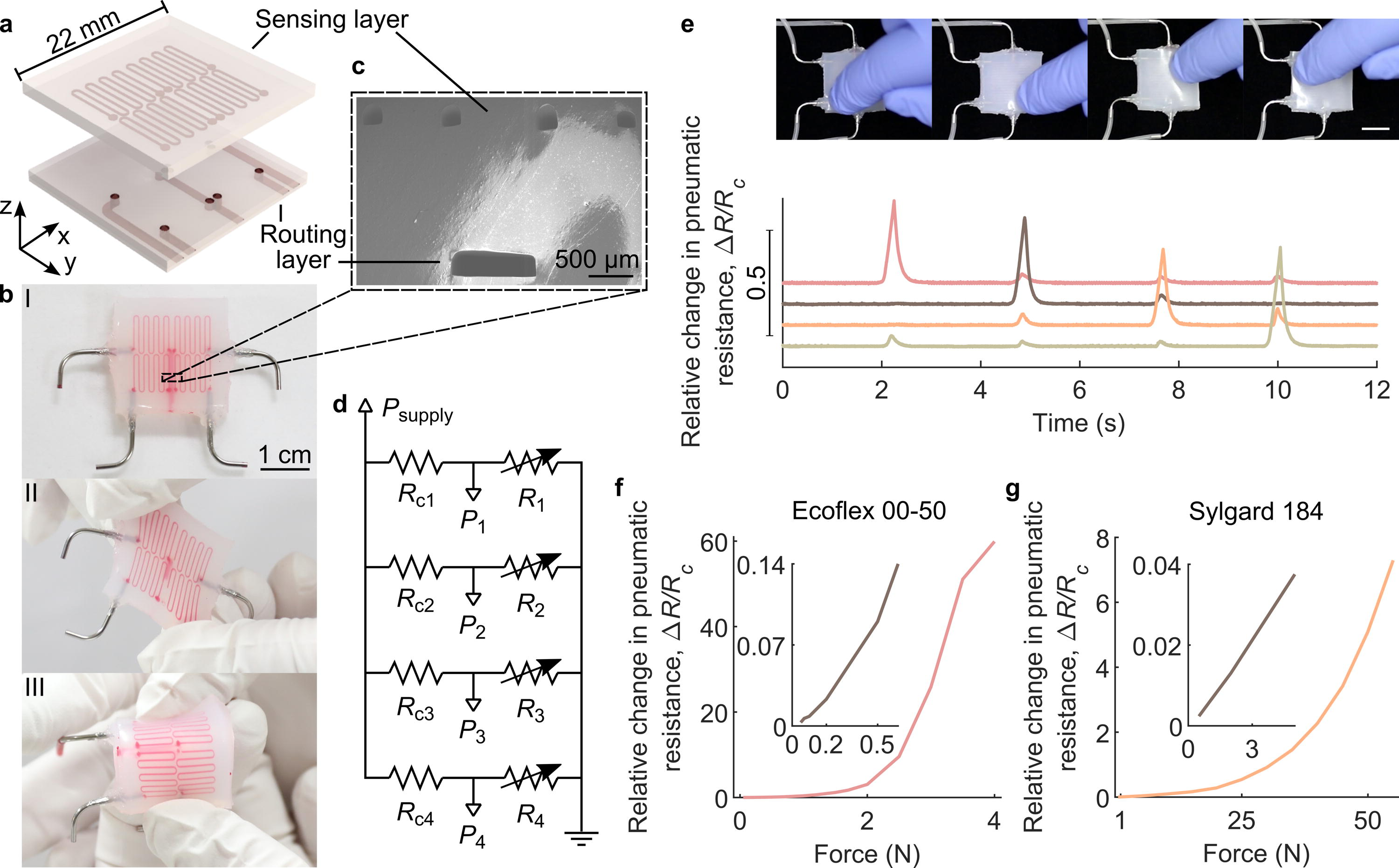
This work reports a soft tactile pressure sensor matrix that outputs a fluidic signal and addresses the limitations of the previous studies by detecting both the magnitude and location of the applied force. The matrix consists of four tactile detection elements (taxels) arranged in a 2 × 2 matrix and is capable of detecting the X- and Y-position of the force as well as the applied compressive normal force in Z-direction (Fig. 1a). Fabricated entirely from soft elastomers, the matrix is flexible and stretchable (Fig. 1b). Each taxel consists of a meandering pneumatic microchannel whose pneumatic resistance is measured as it changes when the cross-sectional area of the microchannel deforms under compression (Fig. 1c). Thus, the meandering pneumatic microchannel serves as the pneumatic analogy of an electrical force sensing resistor (Fig. 1d). As the matrix contains several taxels, the response of different taxels depends on the location of the applied force (Fig. 1e and Supplementary Video S1). This information can be used to not only sense the magnitude of compression force but also to localize it.
Soft pneumatic tactile matrix.
In its default flat configuration, the matrix is primarily sensitive to compressive forces. The position of the compressive force can be deduced from the relative magnitudes of the four sensor signals. We also demonstrate that when an external protruding post is mounted on the device, a force acting on the post is distributed among multiple taxels, and the relative magnitude of the sensor signals depends on the direction of the force. This enables the measurement of forces acting on the post in the X-, Y-, and Z-directions. The device can be used as a soft and stretchable joystick.
In summary, the present work shows a multichannel tactile pressure measurement based on sensors that output pneumatic signals. This opens the way for the creation of entirely fluidic soft devices and soft robots that can detect the magnitude, direction, and location of a contact force without relying on electronics.
Materials and Methods
Design and fabrication of the tactile sensor matrix
Soft silicone elastomers were used to fabricate the soft pneumatic tactile matrix with microchannels in two layers, as shown in Figure 1a. The upper sensing layer contains the meandering microchannels of the taxels, while the lower routing layer provides inlets and outlets for sensing the layer channels. Each taxel was designed to include one meandering channel with seven turns. The cross-sectional area of the channel is 200 μm × 200 μm, and the total length of one channel is approximately 60 mm, giving a total sensing area of 7.5 mm × 7.5 mm per taxel, or 15 mm × 15 mm for the matrix of four taxels. Detailed drawings of the layer designs are presented in Supplementary Fig. S1. Schematic of the matrix is shown in Figure 1a, photos of the fabricated sensor are shown in Figure 1b, and electron micrographs of the channel cross-section in Figure 1c. Two different sensor types were tested: one with an Ecoflex 00–50 sensing layer (Smooth-On, Shore hardness: 00–50) and Dragon Skin 30 routing layer (Smooth-On, Shore hardness: A-30), and another with the whole device fabricated from Sylgard 184 (Dow Corning, Shore hardness: A-50).
The tactile matrix with four taxels was fabricated by casting soft elastomers into molds made with photolithography (negative photoresist SU-8 3050, Microchem). For easier demolding, the molds were treated with trichloro(1H,1H,2H,2H-perfluorooctyl)silane. To fabricate the softer sensor from Ecoflex 00–50, the routing layer was removed from its mold, and the backsides of the two layers were bonded together with the help of a thin layer of an adhesive. We used a small amount of uncured Ecoflex 00–50, the same elastomer that was used to fabricate the sensing layer, as the adhesive between the layers. The adhesive was spin-coated evenly on the flat backside of the sensing layer. A micro stamping device (Fineplacer pico-MA, Finetech) was utilized to align the layers before the bonding and to place the routing layer accurately on top of the sensing layer to bond the layers together. After curing the adhesive between the bonded layers, a needle was used to punch holes through the entire stack of two layers to connect the channels from both layers with vias.
To create closed channels, a thin layer of uncured elastomer was spin-coated on a flat elastomer substrate and partially cured. The stack with open channels and vias was placed on top. The same procedure was repeated to close the channels on the other side. After curing, the device was cut into shape, uncovering the inlets and the outlet. Lastly, metallic inserts were added and sealed with silicone glue (Sil-Poxy, Smooth-On). The fabrication process is illustrated in Supplementary Fig. S2. The fabrication of the tactile matrix from stiffer Sylgard 184 followed the same process, but all bonding was conducted with oxygen plasma (Pico, Diener electronic GmbH + Co. KG, 20 seconds at 30 W and 0.3 mbar pressure).
To transform the tactile matrix into a multi-axis force sensor, a soft protruding post was glued on top of the soft tactile matrix with a thin layer of uncured elastomer. The post (detailed drawings in Supplementary Fig. S4) was fabricated from Dragon Skin 30 elastomer by casting into a 3D printed mold (Clear resin, Form 2, Formlabs).
Experimental setup
The electrical equivalent circuit diagram of the sensor matrix is shown in Figure 1d. In the circuit, R1,2,3,4 represent the different taxels, and Rc1,c2, c 3, c 4 represent the constant pneumatic resistors (Teflon tube, inner diameter = 0.2 mm), connected in series with the taxels. All pneumatic connections were made by using silicone tubes and plastic splitters for junctions. To transduce the fluidic signal of the pneumatic sensor to computer, pressure sensors (015PDAA5, Honeywell, 15 PSI Differential 5V) measured the pressures P1–4 between the taxels and their constant pneumatic resistors (Fig. 1d). A similar pressure sensor was used to measure a constant positive supply pressure Psupply of 60 kPa that was applied to the circuit. A data acquisition device (USB-6356, National Instruments) recorded the data from the pressure sensors.
Using an electrofluidic analogy, the measured pressures can be converted into the pneumatic resistance of the sensor. For small pressures, the compressibility of the gas can be ignored and the pressures and resistances within the channel are related by
44
For the force measurements, a spherical probe (TA-18A, Ø 19.05 mm ball, Stable Micro Systems) was used to compress the tactile matrix with varying tactile forces produced by a mechanical tester (TA.XT Plus, Stable Micro Systems). The full measurement setup is presented in Supplementary Fig. S3.
Results
Characterization of a single taxel
To show that each taxel can detect the magnitude of the applied tactile pressure or force, a varying compressive force was applied on one taxel, and the △R/Rc of the sensor was measured. Figure 1f displays the results for the Ecoflex 00–50 sensor, showing that the sensor signal △R/Rc grows superlinearly until it starts to saturate around 4 N. Supplementary Fig. S5 shows the same measurement for two additional samples, which produce very comparable results. When we repeated the previous measurements with the Sylgard 184 sensor, forces as high as 55 N could be measured before saturation (Fig. 1g). Thus, the force range of the taxel scales with the stiffness of the material: the stiffer the material, the larger the forces that can be measured.
Sensitivity S of the sensors was calculated with
Taking the results in Figure 1f and g together, we conclude that the stiffness of the sensor determines the trade-off between the force range and the resolution of the sensors: stiffer sensors can measure larger forces but the force resolution of the sensor is also reduced.
To study the long-term stability of the softer Ecoflex 00–50 sensor, △R/Rc of one taxel was recorded while maintaining a spherical probe at a constant compression depth on the sensor for 12 hours (Fig. 2a). As seen from the graph, after tactile force had settled, the △R/Rc

Characterization of the pneumatic tactile sensor.
The behavior of the Ecoflex 00–50 sensor was characterized also under dynamic compression. The △R/Rc was recorded while being compressed by a probe that was displaced sinusoidally for 5000 cycles at a frequency of 1 Hz. The peak force applied by the probe was 1 N. Figure 2b shows the results. The graph shows that there was some negligible increase in the response, but overall, the sensor was very stable even under dynamic compression. We attribute this increase in sensor response to small plastic deformations in the sensor. Elastomers have always some degree of plastic deformation under stress, even if most of the deformation is fully elastic and recoverable. To verify the reproducibility of the result, we conducted the cyclic loading test on two more samples with the same design. Supplementary Fig. S7 displays the results, which are highly comparable to those presented in Figure 2b.
To further study the dynamic response of the sensor, we measured the impulse response of the Ecoflex 00–50 sensor by impacting it with a hammer. The length of the tube connecting the measurement circuitry to the sensor was 50 cm. Supplementary Fig. S8a shows the results. After the impact, the sensor showed approximately first-order negative exponential response, from which we calculated the time constant
However, these values depend on the length of the tubing: when we decreased the length of the tubing to 5 cm, the time constant decreased to 27 ± 6 ms (Supplementary Fig. S8b) and the bandwidth was 37 Hz. The system can be understood as a RC circuit, where additional resistances or stray capacitances from the tubing increase the time constant. Thus, the conclusion is that the tubing should be kept as short as possible to avoid decreasing the bandwidth of the system.
For studying the hysteric behavior of the Ecoflex 00–50 sensor, a tactile force of 1 N was applied for five cycles on one taxel and the △R/Rc was recorded (Fig. 2c). To avoid dynamic viscoelastic effects, the strain rate was kept low (0.01 mm/s) during both approach and retraction. The maximum hysteresis was 3.9% when calculated from the average of five cycles. Two other tactile sensors with the same design were also tested, and they had similar negligible hysteric behavior (Supplementary Fig. S9).
Contact localization using multiple taxels
As an initial qualitative demonstration that four pneumatic tactile sensors can be used as a tactile matrix, each taxel one at a time was compressed with a finger. Figure 1e and Supplementary Video S1 show the results of the experiment. When one taxel was compressed, it had a higher response than the other taxels. However, there was also a small response from the neighboring taxels (Fig. 1e).
For a more quantitative test, a mechanical tester and spherical probe were used to apply compressive force of 1 N on the tactile matrix in various points at the horizontal central axis (Fig. 3a) and △R/Rc from all taxels was recorded. When the force was applied on the left-hand side of the vertical central axis dividing the tactile matrix in half, taxels on the left (R1,2 in Fig. 3a) should give a higher response than taxels on the right (R3,4 in Fig. 3a), and vice versa. To show this, we calculated quantity W

Localization with the pneumatic tactile matrix.
To study more thoroughly if the matrix can be used to detect the location of the compression point, the Ecoflex 00–50 matrix was compressed from various points throughout the sensing area while recording the output of all four taxels. Then, we modeled the response of each taxel as a function of the coordinates of the compression point by fitting a Gaussian function
The estimated compression points in comparison to the true compression points are reported in Figure 3c and d. Further analysis of the data revealed that the root-mean-square error of the X-position estimates and the Y-position estimates were 1.67 mm and 1.83 mm, respectively. In other words, after calibration, the coordinates of the compression point can be detected with an accuracy of ∼1.8 mm. These results show that the pneumatic tactile matrix can be used to determine approximately the location of the compression point.
The tactile matrix as a 3D force sensor
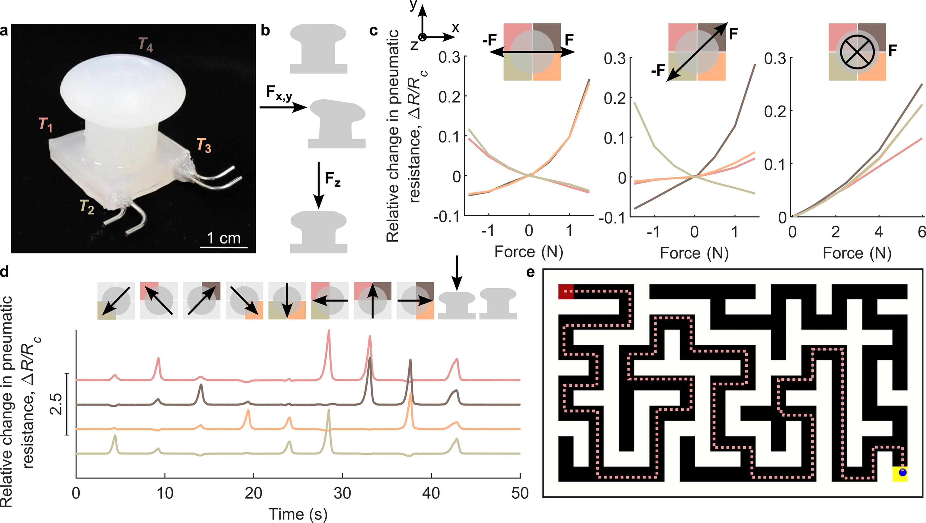
Within a relatively flat device, as we have presented so far, each taxel is mostly sensitive to normal forces. By attaching a protruding post on the tactile matrix (Fig. 4a), forces on the post are distributed among multiple taxels, with the relative magnitude of the sensor signals depending on the direction of the force. Furthermore, when a force parallel to the sensor surface is applied on the post (Fig. 4b), the force creates a torque, which at the base of the post compresses the taxels on the side toward the direction of the force vector, while tensioning taxels on the opposite side. Consequently, the sensor signal of the compressed taxels increases while the sensor signal of the tensioned taxels decreases. In contrast, when the post is compressed with a normal force, the sensor signal of all taxels is increased (Fig. 4b). This allows the post to be used as a 3D force sensor, by finding a calibration mapping of
Soft pneumatic multi-axis force sensor.
To create a multi-axis force sensor, an elastomeric post (Dragon Skin 30) was attached in the center of the Ecoflex 00–50 matrix (Fig. 4a). External forces were applied on the post in varying directions and the △R/Rc of each taxel was recorded. Figure 4c shows the results. Clearly, lateral forces increase the sensor signal of the taxels on the side of the force, while decreasing the sensor signal of the taxels opposite to the force. The compression increases the sensor signal of all taxels, as expected.
The multi-axis force sensing capability of the device including the tactile matrix and the post allows using it as a joystick. Figure 4d shows the sensor signals of the four different taxels when the post is pushed in various directions with a finger. From the graph, it can be seen that the lateral forces increase the sensor signals of the taxels in the direction of the force the most, while normal forces increase the sensor signal of all four taxels. To show that this information is good enough for using the joystick as an input device, we detected the applied force direction and used it to control a character navigating through a virtual maze (Supplementary Video S2 and Fig. 4e). A custom-made MATLAB script was used to read the real-time output of each taxel to control the direction and speed of a character. The velocity was determined based on the measured sensor signals, with three possible movement speeds (slow, medium, and fast) up and down, and similarly for left and right.
Discussion and Conclusions
We fabricated and characterized a pneumatic soft tactile pressure sensor matrix and demonstrated that it can be used to detect the magnitude and location of the contact force or used as the sensing element of a multi-axis force sensor. Table 1 compares our results to different soft tactile sensors reported in the literature.
Comparison of the Proposed Force Sensor to the Sensors Reported in the Literature
Indicates that the value was not reported. Sensitivity was calculated from the reported results as
Estimated from Figure 10c in Ref. 32, 1 mm per second compression rate.
Estimated from Figure 7a in Ref. 38.
Estimated from Figure 2c in Ref. 21.
Estimated from compensated sensor value in Figure 9 of Ref. 40.
Estimated from Figure 2e and g and Figure 3aiii and iv in Ref. 43.
Estimated from Figure 6 in Ref. 42.
The output of the tactile sensor has a super-linear behavior as a function of force (Figs. 1f and g). Thus, the sensor is not necessarily the best fit for measuring the smallest forces, which is also evident in the decreased sensitivity of the sensor when the forces are smaller. Such a super-linear behavior is common in different types of tactile pressure sensors, including resistive tactile sensors based on liquid metals.31,32,38
The hysteresis of our pneumatic tactile sensor was only 3.9%. Compared to resistive tactile sensors based on solid materials with conductive fillers, the hysteresis of our sensor is insignificant, as the hysteresis of the resistive sensors can be over 28.6% (Table 1). 32 The hysteresis is also low compared with the recent work by Choi et al., 42 who reported sensors-based pneumatic resistance and had a hysteresis of ∼17%–35%. Our low hysteresis is more comparable to capacitive and optical sensors.
We used 60 kPa supply pressure for all characterization measurements of the pneumatic tactile sensor. High supply pressure increases the signal-to-noise ratio of our measurements. Supplementary Fig. S10 shows that the signal-to-noise ratio was lower when using a supply pressure of 12 kPa. At pressures exceeding 80 kPa, we have observed the bonded layers of our sensors delaminating. Thus, 60 kPa supply pressure value was chosen to have a high signal-to-noise ratio without risking sensor breakage.
Our sensor is fabricated from soft elastomers that are commonly used to make soft devices for different applications. Any other functional materials (e.g., ionic conductors, liquid metals, or inks) are not used in our sensor, distinguishing it from electrical and optical tactile sensors reported in the literature (Table 1). Comparing our fluidic sensor to optical sensors based on waveguides, one critical problem with optical waveguides is that the waveguide must be relatively straight and that the length of the waveguide is limited because elastomeric waveguides are lossy. In contrast, with liquids and gasses, routing the signal is easier, as channels can have turns, splits, or vias without significantly disturbing the transmission. This suggests that integrating our fluidic sensor into a soft device will be simpler than integrating optical waveguide-based sensors.
Pneumatic sensors reported in literature often use a pneumatic sensing chamber (Table 1), where the air is confined within an elastomeric chamber and the internal pressure of the chamber is measured. The volume change owing to deformation is directly related to the pressure according to Boyle’s law. However, any leakage from the sensing chamber will change the output of the sensor, rendering it unstable and unreliable for long-term measurements. Also, while the authors of chamber-based pneumatic sensors have not reported the long-term stability of their sensors,25,40 silicone elastomers are gas permeable, which suggests that air will slowly diffuse through the silicone in and out of the chambers, compromising the long-term stability of such sensors. In contrast, our tactile sensor is less affected by the gas permeability of silicone elastomers, as there is constant airflow through the sensor and diffusion has no effect on the flow resistance of the channel.
One of the drawbacks of our tactile sensors is that they need additional measurement hardware: a source of pressurized air (air compressor), pressure gauges, and a data acquisition device. For the purposes of recording the data on a computer, we used electrical pressure gauges, but these could have been in principle also fully pneumomechanical gauges, e.g., Bourdon gauges. If the tactile matrix is integrated into a soft robotic device where the actuators are pneumatic, 7 a pneumatic pressure supply is likely already available and can be reused for the sensors. Also, the pressure gauges and data acquisition devices are only needed if the logic of the soft device is implemented using electrical computers. If the logic would also be fluidic, 2 then the sensor signals could be directly connected to the fluidic logic and neither pressure gauges nor data acquisition device would be needed.
To move the tactile matrix further away from the measurement circuitry, only one tube needs to be made long: the tube connecting the sensor to the pressure gauge. All the rest of the tubes (the tubes between the pressure supply, constant resistor, and the pressure gauge) can still be kept short and can always be assumed to have insignificant resistance.
We used 1 mm inner diameter tubing to connect the sensor to the pressure gauge. Assuming Hagen–Poiseuille flows, the fluidic resistance of the tubing scales as ∼ l/d4 where l is the length of the tubing and d its inner diameter. Our microfluidic channels had a width of 200 μm and the inner diameter of the tubing was 1 mm, so they would have comparable fluidic resistance when the ratio of the lengths is approximately 600. We never used tubes longer than 50 cm, and the length of the microfluidic channels was 6 cm (a ratio of ∼8), so for us, the resistance of the tubing was insignificant. As a general guideline, we recommend choosing tube lengths and inner diameters so that their fluidic resistances are insignificant.
Another drawback of our tactile matrix is that the airflow in the pneumatic tubes may become obstructed, e.g., by kinks in the tubing or by clogging. These criticisms are equally valid for all the pneumatic soft devices that have tethered pneumatic connections.5,14 This problem can be somewhat alleviated by using more rigid tubing, but rigid tubing may compromise the mobility of the device. In the future, an untethered soft device with an integrated pressure supply and all channels buried inside the device is expected to be less prone to kinks blocking the channels. Filters can be used to prevent particles from entering the pneumatic channels.
We used metallic inserts to connect the tubing to the sensors because we wanted the connection to be durable. However, plastic inserts can be used just as well (Supplementary Fig. S11) without compromising the functionality of the sensor. In principle, it should be possible to insert the tubes directly into the inlet channels of the routing layer and seal the connection with a silicone adhesive. Currently, the channels in the routing layer are only 200 μm thick, so the routing layer would have to be redesigned to use this technique.
Localization of the contact point can be achieved by increasing the number of sensors in the device. Our tactile matrix contains four taxels, which already enables detecting the point of contact between the taxels. Importantly, even though our matrix had only four taxels as compared with the recent work by Choi et al. 42 which used six pneumatic sensors based on fluidic resistance, we were able to detect the contact location with a sub-taxel accuracy of ∼1.8 mm. The sub-taxel accuracy was based on a fitting procedure using Gaussian functions. Choi et al. 42 used a neural network that classified which of the 9 sensor crossings was being compressed. Each sensor crossing corresponded to an area of 16 × 16 mm, so the contact location could be estimated only very coarsely.
In the literature, soft sensing skin-based electrical resistive matrices with 548 taxels 33 and capacitive matrices with 100 taxels 48 have been reported. With such a high number of taxels, a matrix can be used to infer information about the shape of an object in contact with the matrix. As our matrix contains only four taxels, the information obtained from such a measurement is not yet robust enough to reveal the orientation or shape of an object placed on the matrix. The sensing area of the matrix can be expanded by increasing, i.e., the surface area covered by each taxel, or by increasing the amount of taxels within the matrix. Modifying the sensing layer necessitates redesigning the routing layer to ensure appropriate pathways for inlets and outlets of the microchannels within the sensing layer. In the future, we envision decreasing the size of the taxels and increasing the number of them in the matrix to make the contact point detection more accurate from a wider area and reveal information about the object shape.
In the results shown in Figure 3, we kept the contact force constant when solving the contact point. This allowed us to solve the system only for two unknowns: the x- and y-coordinate of the contact point. If the contact force also varies, then we would have three unknowns: the two coordinates and the force. To solve three unknowns, we should see responses at least in three different sensors. The nonlinearity and saturation of each taxel (Fig. 1f) should also be considered. One approach would be to first calibrate every taxel, to obtain curves like Figure 1f, and then use these calibration curves to convert the sensor measurement to a force measurement. The force at each taxel could be then assumed to be Gaussian centered at the contact point, as we have done in Figure 3c and d.
We demonstrated that by applying an elastomeric protruding post on top of our tactile matrix, the device can be used as a multi-axis force sensor. Unlike many other soft multi-axis force sensors,38,40 our sensor is fabricated entirely from soft elastomers and does not contain any rigid parts.
To conclude, the tactile pressure sensor matrix reported here has comparable or favorable performance to alternative sensing methods. Compared to widely studied resistive sensors based on liquid alloys (e.g., EGaIn), both types of sensors require the fabrication of a microfluidic channel. However, the fabrication of the liquid alloy-based sensor also requires filling the channel with the alloy, making the fabrication more complicated than our sensor, which requires only channels filled with air. Also, while liquid alloy-based sensors are in principle highly stretchable, they also need connecting wires, which are typically rigid (e.g., copper). Such sensors typically fail at the connection site between soft and rigid materials. 32 Thus, our pneumatic sensors may become an easy way to integrate tactile sensing into stretchable devices, especially soft fluidic devices that already have fluidic channels for other purposes, such as soft actuators, 7 soft robots, microfluidic cell culture devices, 49 and rehabilitation devices.46,50
Data and Code Availability
The data generated and analyzed during the study and the scripts used to analyze the data are available from Zenodo at https://doi.org/10.5281/zenodo.11031913 (DOI 10.5281/zenodo.11031913).
Footnotes
Authors’ Contributions
V.L., A.K., M.P., and V.Sh. planned and conducted the experiments. V.Sa. supervised the study. All authors discussed the results. V.L. and V.Sa. wrote the article. V.Sa. conceived the research.
Author Disclosure Statement
The authors declare no competing interests.
Funding Information
The work was supported by the Academy of Finland (Grant numbers #343408 and #331368), the Doctoral Programme in Medicine, Biosciences and Biomedical Engineering of Tampere University, and The Finnish Foundation for Technology Promotion (Grant number #7528).
References
Supplementary Material
Please find the following supplemental material available below.
For Open Access articles published under a Creative Commons License, all supplemental material carries the same license as the article it is associated with.
For non-Open Access articles published, all supplemental material carries a non-exclusive license, and permission requests for re-use of supplemental material or any part of supplemental material shall be sent directly to the copyright owner as specified in the copyright notice associated with the article.