
Abstract
Accurate deformation modeling of soft flexural robots is of high practical importance, especially for high-risk tasks such as surgery. In this study, a new mechanistic model, that is, finite arc method (FAM), for soft robots, for example, tendon-drive, was proposed and validated. First, the catheter was modeled as a finite number of arcs, each with a constant bending curvature, hence the name FAM. Afterward, using a validated Bezier shape approximation, the deformation was parameterized, and the governing equations of the robot were derived. Also, a fast and recursive algorithm was proposed and implemented for the mechanical solution of the robot's deformation. To validate the proposed method, two validation studies were performed. In Study I, the FAM's predicted deformations for eight load cases in each two-dimensional and three-dimensional space on a 40 mm long flexure were compared with the nonlinear finite element method (FEM). In Study II, a representative set of lateral forces on a cardiac catheter (obtained in our previous study) was used to find its FAM-based deformation and was compared with the experimental reference. The error between FAM and FEM deformations was 0.23 ± 0.89 mm with computation times of 3 mseconds (FAM) versus 1244 mseconds (FEM). Also, the error of FAM compared with ground-truth in Study II was 1.41 ± 1.47 mm with a computation time of 7 mseconds. The proposed method showed acceptable performance for the accurate prediction of highly complex large deformations in real time.
Introduction
Background
Flexural robots are a class of soft robots that have been used in interventional robotics frequently. For example, flexural robots have been used in catheter ablation therapy in the left atrium.1,2 This treatment has become the gold standard for the treatment of cardiac atrial fibrillation, the most prevalent cause of cardiac arrhythmia and the leading cause of hospitalization in cardiac electro-physiology. 3
Figure 1 depicts a schematic view of the RFA catheter inside the atrium during the ablation procedure. This procedure is minimally invasive; thus, the surgeon does not have a direct vision of the trajectory of the shape of the catheter. Instead, they obtain such information through real-time X-ray imaging, that is, fluoroscopy.

The schematic shape of steerable ablation catheters in the left atrium during ablation interventions.
To avoid the health risks associated with X-ray exposure, remote leader–follower robotic platforms with tendon-driven catheters have been proposed recently. 4 Such systems have enabled surgeons to not only move away from the X-ray exposure risk zone but also do intervention from miles away.5,6 Similar to other novel medical technologies, simulation-based training is a clinical need for shortening surgeons' learning curves and increasing the adoption rate of flexural medical robots.
To this end, having a fast and accurate computational model that can reliably predict the deformed shape of the flexural robot, for example, catheter, in real time is a requirement. In this study, we have proposed and validated a fast and accurate model for flexural robots that has superior performance in computational time compared with the most accurate computational method in the literature, for example, the finite element method (FEM).
Related studies
In the field of soft robotics, the mechanical modeling of these systems has evolved through various phases, each marked by distinct methodologies and theoretical advances. Initially, the focus was on discretization strategies to manage the infinite degrees of freedom inherent in soft robotic systems.7,8 However, while simplifying the equations of motion, this approach often led to a loss of critical information and inaccurate deformation predictions.
As a countermeasure, researchers began incorporating continuous shape interpolation functions, such as Bezier splines, for better deformation modeling and integration into kinematic balance and constitutive equations.9–11
The modeling of large deformations in flexural robots presented unique challenges, inspiring a variety of methods.9,12 In this regard, Cardoso and Furuie 13 modeled a guidewire using a series of elastically connected vertices. The series of vertices would model the backbone of a flexible catheter. Their model was fairly accurate for small deformations, that is, deflection less than 15°, but would become erroneous at large deformations.
Several methods for modeling large deflections of flexures have been proposed, for example, the elliptical integral approach, 14 numerical integration approach with iterative shooting techniques,15,16 incremental finite element or finite difference method with Newton–Raphson iteration techniques,17,18 mechanics-based static and dynamic models,19,20 Cosserat rod model approach, 21 and data-driven method,22–24 These approaches have been adopted in various studies on flexural robots.
For example, Khoshnam et al. 11 used the beam theory to simulate the distal portion of a catheter. On the other hand, traditional beam theories are not immediately applicable to large deflections. With deflection angles larger than 10°–15°, the beam theory becomes erroneous. Further, Cotin et al. 25 constructed an incremental finite element model based on the beam theory, assuming the catheter is made up of wire-like segments. Each of these approaches addressed specific aspects of large deformation modeling but also came with limitations such as computational inefficiency or limited scalability. 26
Two particular approaches that gained attention were the Piecewise Constant Curvature (PCC) and variable curvature models.27,28 The PCC method simplified the robot into segments with constant curvature, easing control and planning but potentially overlooking nuances in behavior under significant deformation. Variable curvature models, offering a more dynamic representation, provided greater accuracy in complex environments but at the cost of increased computational demand and complexity in control strategies. 25
For a tendon-driven soft manipulator whose shape is described by the PCC, Camarillo et al. 29 presented a comprehensive derivation for both forward and inverse kinematics utilizing parallel algorithms. Sadati et al. 30 provided a critical analysis of the PCC parametrization model. Their study indicated that the application of this model encounters limitations, particularly in its standard form. On further examination, it is revealed that the relaxation of the PCC constraints yields more favorable outcomes. This observation underscores the need for a nuanced approach in the implementation of the PCC parametrization, suggesting that its rigid application may not be universally effective across various scenarios.
In recent years, the Cosserat rod theory has emerged as a significant advancement, presenting a unified set of equations for both large and small deformations of flexural robots. While offering a sophisticated modeling approach, Cosserat rod models often lack analytical or quick-solving solutions, posing challenges for real-time applications.31–33
The continual evolution in soft robot modeling reflects a broader trend within robotics, where the complexity of theoretical tools has exponentially grown, often intersecting with other scientific disciplines such as continuum mechanics, computational mechanics, and computer graphics. These advancements highlight the shift from simplistic models to more complex, accurate representations, acknowledging the trade-off between accuracy and numerical usability for robotic purposes. 34
Soft robots, unlike traditional rigid robots, are continuum systems characterized by highly nonlinear partial differential equations that are generally not analytically integrable. This nature of soft robots necessitates a more nuanced understanding of continuum mechanics, where the robot's configuration is parameterized through positional fields dependent on time and material coordinates. Modeling these systems, thus, requires a deep understanding of the dynamic principles and constitutive laws that govern the stress-strain relationships within the continuum medium. 33 The mechanical modeling in soft robotics is marked by an ongoing quest to balance computational feasibility with the need for accurate, detailed representations of complex systems.
From initial discretization strategies to sophisticated models such as the Cosserat rod theory, each method has contributed to a richer understanding of these intricate systems, underscoring the dynamic and ever-evolving nature of research in soft robotics. To alleviate the aforementioned limitations for fast and accurate large deformation and variable curvature computation on flexural robots, we have proposed a new method based on Bezier shape approximation and an analytical solution on a finite set of arcs along the flexure. The method is called the finite arc method (FAM), was preliminarily tested for accuracy and speed, and was compared with finite element analysis as the most accurate method in the literature.
Contributions
The main contributions of this study are:
Derivation of large deformation kinematics of soft flexural robots based on Bezier shape approximation. Analytical solution of deformation of a single two-dimensional (2D) arc robot subjected to generalized forces and moments. Proposing a universal FAM model by the generalization of the 2D single arc solution to three-dimensional (3D) flexures. Implementation and validation of the proposed FAM model for representative 2D and 3D robot actuation scenarios. Experimental validation of the proposed FAM model for a surgical interventional use-case, that is, robotic cardiovascular catheter.
Methodology
In this section, first the derivation of the kinematics, constitutive equation, and moment balance of a single-segment beam with PCC deformation assumption (single arc) is provided. Afterward, the proposed FAM model is constituted and analytically solved by aggregation of multiple single-arcs hence, extending the PCC assumption. By decreasing the discretization resolution, we have shown that the proposed methodology exhibits high computational performance and accuracy in modeling large beam deformations with variable curvature.
Kinematics: Single arc
The kinematics derivation of the flexural robot was based on the discretization of the flexure into several finite arcs, each represented with a third-order Bezier curve that satisfied a single-plane constant bending radius condition. Single Bezier arc kinematics for a flexural robot has been previously derived and validated in Ref.
9
Figure 2 depicts the deformed shape of a flexural robot as a slender beam. In a previous study, the author showed that given the tip position of a circular arc in bending plane

Schematic deformed shape of the tendon-driven continuum arm Bezier spline centerline in Γ-plane. 9
where
Also, the control points in the
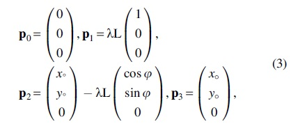
with
which is only a function of
For the described bending, the only kinematic variable was the geodesic bending curvature
with
The Bezier curve approximation used in the FAM represents a significant simplification when compared with the PCC model. In the FAM, a single parameter, the bending angle, is employed to define the arc of the soft body. This approach contrasts with the PCC model, where the radius of curvature or bending angle for each segment is considered independently.
The Bezier curve provides a more intuitive and computationally efficient means of capturing the continuous nature of bending in soft robots. Unlike the PCC model, which requires handling each segment's curvature separately, the Bezier curve approach allows for a smoother and more integrated representation of the entire structure, facilitating faster computations without compromising the accuracy required for applications such as surgical robotics. In addition, using a Bezier shape approximation allows for choosing various classes of such hodograph curves, for example, twist-free, minimal twist, length-preserving, etc., 35 which would allow for different reduced order modeling of soft robots.
Constitutive equation
The Euler-Bernoulli constitutive relationship between the bending deformation, that is,
with
Moment balance: Single arc
For the sake of generality, it was assumed that flexure bears an external force and an external moment at the tip. This loading is valid for tendon-driven catheters as a representative example. Figure 4 shows the free-body diagram (FBD) of the flexure at equilibrium. The flexure is bent as a result of an external tip force
In the case of tendon-driven catheters, the tip force and moment are the results of the pulling in the catheter's steering tendons. Quasi-static equilibrium of the FBD depicted in Figure 4 shows that the force and moment at the base of the flexure applied to it from its anchorage are:
Also, the moment balance equation at any given point
Substituting the constitutive definition of
This equation is a vectorial equation with two trivial scalar equations (
with
Deformation solution
As stated earlier, Equation (12) is under-determined with two unknowns
To the best of the authors' knowledge, this approach is unprecedented in the literature. To find the

Functional

Afterward, the functions

where  Given the polynomial representation of

with

Imposing the necessary condition for minimizing

To solve Equation (21), the analytical form of
Finite arcs: 3D generalization
In general, the deformation occurring along the flexure is not planar if forces and moments are 3D. Nevertheless, we hypothesized that the general shape of the flexure could be obtained by the aggregation of finite deformations of discretized arcs. We assumed that each arc would undergo a planar deformation and a torsional deformation.
Thus, each arc would necessarily bend in a plane perpendicular to the total bending moment vector acting on it. Thus, in the following, we describe finding the moment plane (
As shown in Figure 3, the

A representative continuum arc before bending (straight shape) with external loading. The arc's deformation occurs in the bending plane Γ denoted with normal
This approach assumes that the normal to the bending plane is parallel to the total bending moment vector. We chose this assumption based on the observation that, in most practical applications, the dominant bending moments align with the plane's normal. Equation (19) reflects this by excluding a component in the x-direction. This exclusion is justified as, typically, bending moments inducing significant deformation in soft robots, such as catheters primarily occur in the plane perpendicular to the robot's primary axis.
This approach differs from the PCC model, where an additional parameter defines the bending plane, offering a more streamlined and computationally efficient method while still capturing the essential dynamics of bending. As a result, the first step was to obtain the bending plane and, by using the normal of this plane, define a new coordinate system in which the deformation is calculated.
The normal vector of bending plane
while the x-axis is selected along the flexure, and y and z-axes were selected arbitrarily. Therefore, the normal vector
with
with
Using the vectors
which was used to transfer the deformation from BCS to GCS. The rotation matrix can also be obtained using Rodrigues' rotation formula, which leads to the same result.
Torsion
An introducer sheath is used to introduce a catheter into the vasculature, generating friction that hinders mobility. This friction demonstrates the minimum force required to move the catheter during an interventional operation. 36 During interventional operation, when a steerable catheter has one or two degrees of freedom, the tip cannot bend in all directions at the same time. Therefore, a twisting moment (torque) must be applied to overcome vascular friction during the operation and rotate the catheter. The torsional deformation, despite its nature, results in a planar effect due to the specific geometry and constraints of the soft robotic structure, particularly in the context of flexural robots such as catheters.
To include the torsion in the solution schema, the continuum robot was assumed to have a uniform cross-section along its length. In this case:
where
Therefore, the torsional rotation matrix
Hence, the total rotation matrix to transfer the deformation, including moment and torsion, can be defined as:
Deformation solution
Based on the solution method provided in Equation (21), it was hypothesized to discretize the flexure into N segments that each segment's deformation would be a single bending radius flexure. This way, the total deformation of the flexure would be obtained by aggregating all the deformations from the base
Figure 4 depicts the proposed segmentation schematically. To the best of the author's knowledge, this approach is unprecedented in the literature. This angle for the next section

The FBD of a deformed flexural robot with multiple circular arc segments. FBD, free-body diagram.
where:
As a result, the amount of force and moment exerted on the endpoint of section
This process continues in a similar way to transmit force and momentum to all sections from the beam's free end to the base. In the end, the final deformed shape of the flexure was constructed by augmenting the deformed shape of segment
where L

Our method of initiating the solution from the last segment and proceeding backward is highly effective for analyzing problems with pose-independent external forces, such as actuation forces and moments in tendon-driven catheters and soft robots. We acknowledge this limitation when dealing with pose-dependent forces, such as gravity or contact forces whose component resolution in the “deformed” coordinate systems are unknown when solving Equation (21).
Nevertheless, for many intraluminal procedures such as those in cardiovascular applications, the catheter's weight is negligible compared with the actuation forces; thus, the proposed method may not lead to significant errors. We have shown the validity of this speculation in the presented validation studies of this work. To alleviate this limitation in the future, an implicit solution schema of a system of Equation (21)-s for all the segments could be investigated.
Validation Studies
Study I: Simulation-based validation
Protocol
Figure 5 shows eight planar and eight spatial load-cases solved by FAM and compared with FEM. The developed FE models were of 40 × 6 mm size. The flexural rigidity of the robots was 750 Nmm2. The FE simulations were performed in Abaqus CAE 2020—Student Edition.

Eight load cases on a representative flexure for Study I in
Derivation of the analytical form of Equation (21) was performed in Maple 2019 (Maplesoft; Cybernet Systems Co., Ltd.), and FAM was developed in C++ programming language. For linear algebraic operations and numerical calculations, GPU-accelerated Armadillo library was used. The FE model of the robots was meshed with quadratic beam elements of 50 elements.
The FE results were not sensitive to mesh refinement for the number of elements used in the simulation. Also, the number of segments for the FAM solution was
Results
To compare the accuracy and computational performance of the FAM method with FEM, two series of loadings that represent various extrinsic loadings on soft robots, for example, tendon-driven robots, were performed, that is, planar deformation (where loadings were co-planar) and spatial (where loadings were not co-planar).
Planar deformation
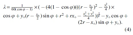
Figure 6a shows the deformed shape of the catheters after applying force and moment in eight different cases (Fig. 5a). In each load case, each segment was first

Comparison of Finite Arc Method and Finite Element Method Solutions for Eight Load Cases in Two-Dimensional Simulation
FAM, finite arc method; FEM, finite element method; SD, standard deviation.
The comparison of the estimated tip position with the reference showed that the tip position estimation along the x-axis had an average error of −0.27 ± 0.90 mm and along the y-axis had an average error of −0.25 ± 0.94 mm. The mean-absolute-error (MAE) of the deflection estimation with respect to the reference was 0.29 ± 0.48 along x direction and 0.39 ± 0.58 along y direction with root-mean-square of 0.4865 and 0.5732 mm respectively (Fig. 6b, c).
Spatial deformation
Figure 5b shows eight different load-cases in the 3D simulation. Eight simulations were performed and compared with the FEM (Fig. 7 and Table 2). The catheter model was similar to before, with flexural rigidity of 1500 Nmm2. The comparison of the estimated tip position with the reference showed that the tip position estimation along the x-axis had an average error of +0.36 ± 0.98 mm and along the y-axis had an average error of −0.18 ± 0.56 mm, and along the z-axis had an average error of −0.13 ± 0.37 mm.
Comparison of FAM and FEM results in deflection estimations for eight load cases on soft flexures in 3D simulation.
Comparison of Finite Arc Method and Finite Element Method Solutions for Eight Load Cases in Three-Dimensional Simulation
The MAE of the deflection estimation with respect to the reference was 0.44 ± 0.28 mm along the x direction, 0.52 ± 0.20 mm along the y direction, and 0.51 ± 0.14 mm along the z direction with root-mean-square of 0.5222, 0.5590, and 0.5284 mm respectively.
Segmentation effect
To investigate the segmentation effect, load case 4 was selected as the worst-case scenario and solved with a series of segmentation numbers. Figure 8a shows a representative set of final shapes of the deformed catheter with various segmentations. The segmentation was changed between 1 and 5000, and the absolute error of the flexure's tip position was studied (Fig. 8b). It was observed that by increasing the number of segments in the model from 1, the error dropped drastically and hit a minimum of 12 segments.

Effect of segmentation,
The absolute error value was less than 3 mm (7.5% of length) between N = 12 and 500. For N > 500, the error steadily increased. The reason might be because each arc's deformation is obtained through minimization. At extreme segmentation (N > 500), the arcs tend to straight lines; thus, the residual error of the minimization increases as it cannot find a finite number for the curvature (
Torsional warping effect
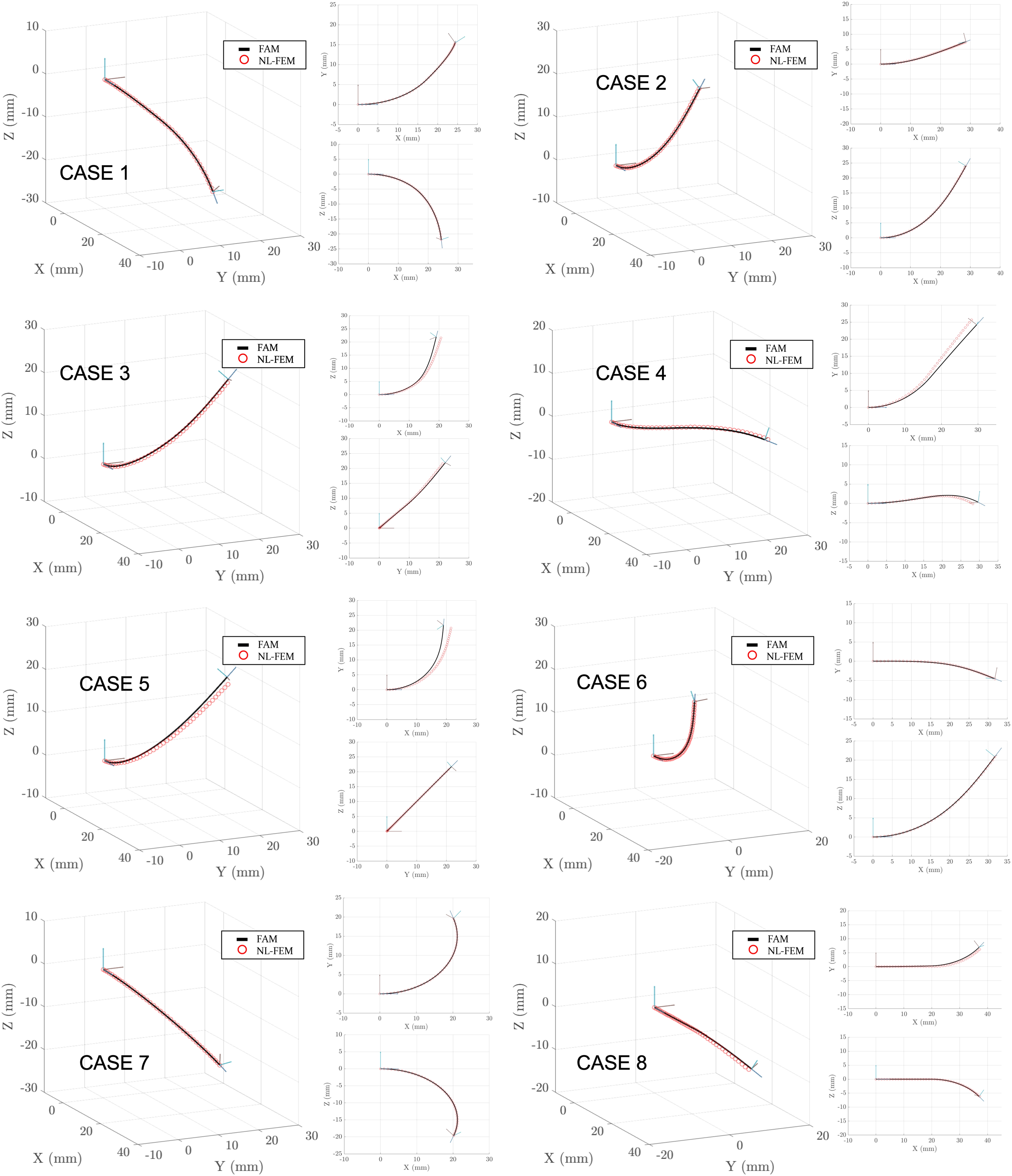
Load case 1 in the 3D simulation was selected to investigate the effect of torsion and solved by increasing the torsion moment from 0 to 50 mN.m (Fig. 9). Table 3 summarizes the tip position error for different torque values applied to the continuum robot's tip. Also, by defining normalized torsion
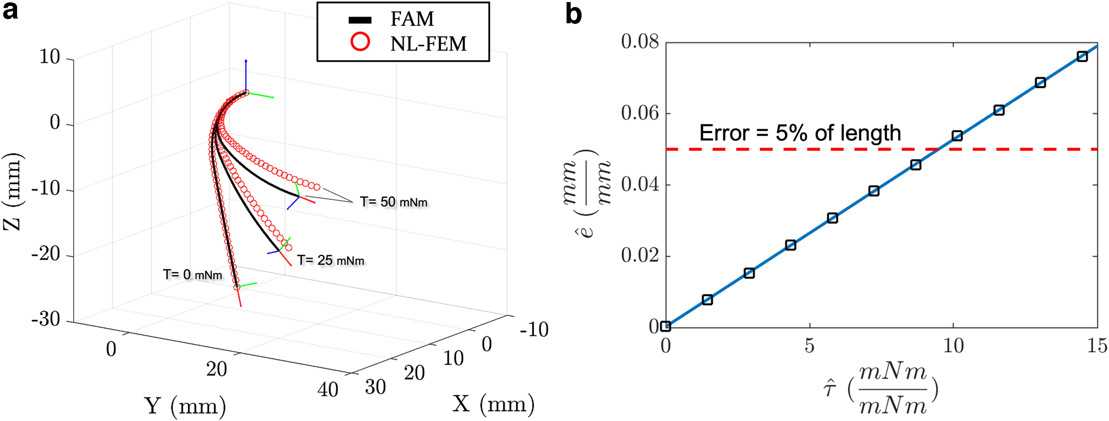
Comparison of Finite Arc Method and Finite Element Method Solutions for Different Values of Torsion Applied to the Tip of the Continuum Robot
with m, g, and rg as the segment's mass, gravity, and nominal radius of gyration before deformation, the applied torque was normalized. Similarly, the tip position error was normalized with respect to the robot's length. It has been observed that by increasing the twist angle, the error increased because of exiting the assumption of decoupling solution.
Study II: Experimental validation
Setup and protocol
The proposed method was integrated with a representative robot-assisted intervention (RCI) system previously developed by the authors in Refs.37,38 to test the feasibility of integrating the proposed method with RCI systems (Fig. 10a). The user would transmit the measured rotation and insertion length to the patient module. As shown in Figure 10a, the CataLyst robot (Thermo Fisher, WA, USA) was used to align the entry angle of the femoral vein of the vascular model (SAM plus; Lake Forest Anatomical, Inc., IL, USA).

Setup used in validation study-II
The forces and their location were extracted using an image-based method developed by the authors in Ref. 38 The total length of the catheter was 504 mm with a hollow cylinder cross-section with an outer diameter of 2.14 and a thickness of 0.29 mm. Its material is linear elastic with Young's modulus of 1592.3 MPa, and Poisson's ratio of 0.395. 38 Three reaction forces were captured in the deformed shape of the catheters depicted in Figure 10b.
The first force f1 had a magnitude of
The estimation of contact forces from our experimental setups involved a detailed analysis of the deformed shapes of the catheters under applied forces. Utilizing an image-based method developed in our previous work,38,39 we captured the deformation patterns of the catheters. From these patterns, the location and magnitude of contact forces were inferred. This estimation process involves correlating specific deformations with known force applications, allowing us to reverse-engineer the forces responsible for observed deformations. This method provides a robust approach to understanding and quantifying the interaction forces between the catheter and its environment, which is crucial for the accurate modeling of soft robotic systems in real-world applications.
Results
Figure 10c compares the magnitude of the reference with the estimated deformation of a catheter. As the comparison showed, the FAM results were in fair agreement with the observed deformation. The maximum absolute error of deflection along vertical axis y was 4.95 mm (8.5% of the maximum deflection), and it was at the tip. The FAM method resulted in a larger estimation error at the tip, which might be due to error accumulation through the segments along the flexure.
A similar trend was observed in Study I on the simulated deformation. Nevertheless, the average relative error of the experiments was 1.41 ± 1.47 mm. Another finding was that the average computational time of the proposed force estimation method was less than 3 mseconds with C++ implementation. These findings showed that the proposed method could successfully simulate the deformation of flexures in real time.
Table 4 compares the performance of the proposed method with representative studies. The comparison showed that the proposed method exhibited improvement in both accuracy and computational cost. Also, the validation studies showed acceptable accuracy of the proposed method in solving the deformation under various loading conditions. In future studies, this work will be extended to accommodate nonlinear constitutive equations in the solution of the FAM.
Comparison of Accuracy and Computation Time of Finite Arc Method and Representative Studies
2D, two-dimensional; 3D, three-dimensional.
The authors have previously proposed such integration with Cosserat rod models in Refs.40,41 The proposed method also can be used in sensor-based42–46 and sensor-free bending-based10,38 force estimation for haptic rendering applications, for example, for RCI systems.47,48
Conclusion
In this paper, a new modeling method and its solution for soft flexural robots, such as tendon-driven catheters, with large deformation using the FAM was proposed and validated. The fast solution of the model solution was made possible by using the proposed Bezier spline shape approximation and discretizing the catheter into a finite set of circular arc segments. Also, combined with an RCI setup, the proposed modeling approach exhibited an acceptable performance in terms of accuracy for real-time force estimation on flexible catheters in contact with tortuous vascular models. The proposed method showed significant improvement in accuracy and reduction of computational cost for direct and inverse mechanistic problems pertaining to the deformation of flexural robots.
Footnotes
Author Disclosure Statement
No competing financial interests exist.
Funding Information
This study was supported by McGill University, Research Institute of McGill University Health Center (RI-MUHC) [Grant Number 10910], Fond de recherche du Quebec—nature et technologies (FRQNT) [Grant Number 315939], and Montreal General Hospital (MGH) Foundation [Research Award 9204].