
Abstract
Lizard is a soft mobile robot equipped with six three-spoked whegs to negotiate uneven terrain and a flexible spine to enhance maneuverability and obstacle-climbing performance. The flexible spine consists of an origami bellows structure fashioned from laser-cut plastic sheets and actuated by three cables attached to Direct Current (DC) motors at the base of the module. Lizard is highly maneuverable and adept at traversing various types of rough terrain. It has a turning radius as low as 18 cm, which allows Lizard to navigate difficult passageways and cluttered environments. Lizard can also travel at 39.20 cm/s on flat carpeted terrain and climb obstacles up to 132 mm tall or 2.40 times higher than the length of the wheg. In addition, we discuss CHOMP+, an optimal motion planning algorithm based on constrained Covariant Hamiltonian Optimization for Motion Planning (CHOMP), for mobile robots with a limited turning radius. We experimentally demonstrate CHOMP+ generating a curvature-bounded path for Lizard through a populated environment in 213 ms.
Introduction
Mobile robots are a popular area of study for their potential applications in a variety of fields, including disaster response, industrial inspection, and automated construction. However, many potential applications require the robot to reliably negotiate complex environments, which is still an open challenge in the mobile robotics field. An effective mobile robot should be able to maneuver through complex environments, adapt to different terrains, and climb various obstacles.
Wheels and legs are two forms of locomotion common in mobile robotics. Wheels are simple and highly energy efficient on flat terrain; however, they are less effective on rough terrain. Legs provide greater mobility on rough terrain, but they require more complex planning and control algorithms to coordinate a larger number of degrees of freedom (DoF). Whegs, or wheel-legs, combine the simplicity of wheels with the versatility of legged systems.1,2 Since their introduction, whegged robots have demonstrated the ability to navigate on rough terrain, 3 traverse stairs,4,5 and climb obstacles larger than their whegs. 6 However, many of these whegged robots feature a long rigid body, which may limit their maneuverability in tight spaces such as winding passageways or cluttered environments.
Some whegged robots have incorporated an articulated body with a single spinal joint to improve obstacle clearance and stability.6–11 However, the spinal joint does not enhance their maneuverability. Similarly, the Advanced Security Guard (ASGUARD) features a passive compliant spinal column, which improves traction on uneven surfaces. However, similar to the body flexion joint, it has no impact on maneuverability. 12
Recent work on whegged robots has taken inspiration from vertebrates like lizards, which have flexible spines that allow them to make agile maneuvers and conform to complex environments. Ai et al. introduced the crawling soft robot (CSR), a whegged robot with a flexible continuum spine.
13
CSR featured a pneumatically actuated spine attached to four passively actuated whegs. The whegs were coupled to a ratchet-pawl mechanism, which only allowed them to rotate in one direction. This allowed CSR to crawl by periodically actuating the spine. Using this technique, the CSR could traverse slopes up to
Similarly, Siles et al. introduced FRESE II, a whegged robot with a passive continuum body constructed from modular tubing.
14
The flexible spine allowed FRESE II to successfully navigate through narrower environments; however, it limited the robot’s obstacle-climbing performance. Niu et al. presented SoSpider, a whegged robot designed to explore planetary lava tubes.
15
SoSpider consisted of six actively driven whegs in addition to an untethered pneumatically actuated flexible spine. Although SoSpider could bend its spine up to
In this article, we introduce Lizard, a novel whegged robot with a flexible continuum spine for improved adaptability and agility in complex environments. Lizard is equipped with a cable-actuated flexible spine, which provides sharp turning capability (with an 18 cm turning radius) and improved obstacle-climbing performance. In contrast to prior whegged robots with flexible pneumatic spines that limited their maneuverability or operational space, Lizard’s electromechanical spine enables it to navigate tight, winding passageways and surmount obstacles up to 13.20 cm (2.4 wheg lengths, or WL), all while maintaining a large operational range.
In addition, we introduce CHOMP+ (Covariant Hamiltonian Optimization for Motion Planning), a curvature-constrained motion planning algorithm tailored to Lizard’s unique design. CHOMP+ enhances the traditional CHOMP16–18 algorithm by incorporating virtual obstacles to restrict curvature, ensuring that planned trajectories adhere to Lizard’s physical actuation limits. We demonstrate CHOMP+ generating a path through a cluttered environment in 213 ms and show that Lizard can track the trajectory with minimal deviation (13.24 mm root mean square [RMS] error).
The remainder of the article is organized as follows: The second section details the hardware description of the Lizard robot, including the system architecture, the flexible spine design, and the wheg design; the third section details the CHOMP+ algorithm; the fourth section presents our experimental results; and the fifth section details our conclusions.
Hardware Description
Figure 1 shows a Computer Aided Design (CAD) diagram representing the first module of the Lizard robot. Subsequent modules have a nearly identical design, however, with two whegs rather than four. In this section, we detail Lizard’s system architecture as well as its design, assembly, and kinematic modeling.

(Left) A CAD diagram depicting the first Lizard module. The module is driven by four whegs coupled to a flexible origami spine and powered by a rechargeable Li-ion battery. The whegs and flexible spine are actuated by Pololu Direct Current (DC) gearmotors with each motor controlled by a custom Smart Motor Driver Printed Circuit Board (PCB). (Right) The Lizard robot is equipped with two flexible spine modules and six whegs.
System architecture
Figure 2 illustrates the system architecture of the two-module version of Lizard. The first module consists of an ESP32 acting as the wireless receiver, a 7.4V 1500 mAh rechargeable Li-ion battery, three Pololu 298:1 Micro Metal Gearmotors to actuate the spine, and four Pololu 150:1 Micro Metal Gearmotors to drive the whegs. A custom Smart Motor Driver PCB is situated on the rear of each motor. The Smart Motor Driver contains an encoder, a current sensor, a Shanghai Mingda Microelectronics MD9927 motor driver, and an ATMega328 microcontroller. The second Lizard module has a similar system architecture; however, the second module has two whegs rather than four. This system architecture is simple, maintainable, compact enough to fit within the slim profile of the body, and easy to expand with additional modules for improved obstacle climbing and stability.

The Lizard system architecture. Lizard is wirelessly operated with an Xbox gamepad. The controller sends the desired robot velocity
The system is manually controlled with an Xbox gamepad controller, which sends the desired robot velocity
Flexible spine
Similar to our prior work on Salamanderbot,
19
OriSnake,
20
and CLARA,
21
Lizard uses the origami actuator introduced by Santoso et al. as a flexible spine.
22
The origami actuators consist of three polyethylene terephthalate (PET) sheets with the Yoshimura origami crease pattern laser cut into each sheet. After they were laser cut, the PET sheets were manually folded together by inserting the forks along the sides of each sheet into rectangular slots on adjacent pieces, creating a triangular bellows structure. Plates 3D printed from polylactic acid (PLA) were then attached to either end of the bellows, and three Pololu N20 DC gearmotors with a 298:1 gear ratio were rigidly attached to the base plate with pulleys coupled to the shaft of each motor. Cables attached to each pulley were threaded through holes along the vertices of the bellows structure and anchored to the end plate. By rotating the gearmotors, we can change the length of the cables to actuate the module. The assembled actuator is lightweight, low-cost, and capable of bending up to
Flexible Spine Design Parameters
We model each section of the flexible spine as an arc with curvature

Flexible spine bending demonstration and kinematic model. A demonstration of one flexible origami spine module
Whegs
Lizard features six actively driven whegs (Fig. 4), each with three curved spokes distributed evenly around the hub. We chose three spokes, as opposed to two or four spokes, as a tradeoff between obstacle climbing performance and motion smoothness. 24 Although obstacle clearance increases with wheg diameter, we designed the whegs with a diameter only 2 cm larger than the plates they are mounted on to ensure that Lizard can navigate in small-diameter tunnels. Thus, each spoke of the wheg is 55 mm long and 5 mm wide.

The three-spoked wheg design. (Left) A closeup drawing representing the curved three-spoke wheg design with a 55 mm wheg length; (right) a photo of the 3D-printed wheg with sleeves situated on the ends of each spoke for increased traction. The whegs were printed with silver polylactic acid (PLA), and the sleeves were molded from EcoFlex 00-50 silicone.
The whegs were all 3D printed from PLA and coupled directly to a Pololu N20 DC gearmotor with a 150:1 gear ratio for actuation. The whegs were later fitted with a silicone molded sleeve for increased traction. Each sleeve was molded out of EcoFlex 00-50, which was chosen for its high traction and durability.
Steering
Lizard maneuvers through an environment by bending its flexible spine in the lateral direction to change the robot’s heading while driving the right and left whegs at differing speeds related to the curvature of the flexible spine.
Figure 5 is a simplified sketch of one Lizard module turning about its instantaneous center of curvature (ICC). The pink components represent Lizard’s whegs, while the red arc segment between the whegs represents a flexible spine module. Based on this model, we derived Equations (4) and (5) to determine wheg velocities

A simplified sketch of the differential drive kinematic model where ICC is the instantaneous center of curvature,
Motion Planning with CHOMP+
In this section, we present CHOMP+ (Fig. 6), an optimal motion planner based on the constrained Covariant Hamiltonian Optimization for Motion Planning (CHOMP) algorithm with additional constraints on the curvature of the trajectory.

A flowchart depicting the CHOMP+ (Covariant Hamiltonian Optimization for Motion Planning) algorithm.
Objective function
We formulate the objective function (6) as the weighted sum of two terms
Similar to Ratliff et al., we represent the trajectory
Curvature constraints
To account for limitations on Lizard’s turning radius, we developed a method to generate virtual obstacles to perturb the trajectory when its curvature exceeds Lizard’s minimum turning radius. The gradient of the potential generated by virtual obstacles nudges the trajectory during each iteration until its curvature falls below the upper bound. By ensuring that the final trajectory is free of collisions, we can guarantee that the path satisfies the curvature constraint. The procedure for generating virtual obstacles is outlined as follows:
We first calculate the curvature at each point along the path to find where the curvature exceeds the maximum curvature of Lizard’s origami body. A circular virtual obstacle is generated for each point exceeding the maximum curvature with a radius given by the radius of curvature at that point. The origin of the virtual obstacle is placed at the center of curvature such that the point in question lies on the border of the virtual obstacle. The virtual obstacles are combined with the set of real obstacles to calculate the obstacle cost of the current trajectory. Once the trajectory has been updated, the virtual obstacles are discarded in preparation for the next iteration.
Orientation constraints
To constrain the initial orientation of the trajectory
Update rule
The update rule includes the gradient of the cost function to reduce the cost of the subsequent trajectory, paired with additional terms to project the unconstrained update onto a constraint surface where
Results and Discussion
We characterize Lizard’s performance in terms of its ability to maneuver, climb obstacles, and traverse various terrains. In addition, we compare these performance metrics to various robots with non-transformable whegs and demonstrate the CHOMP+ algorithm calculating a collision-free curvature-constrained path.
Maneuverability
As previously discussed, Lizard’s flexible spine allows it to adapt and maneuver in complex environments. Each flexible spine module can bend up to
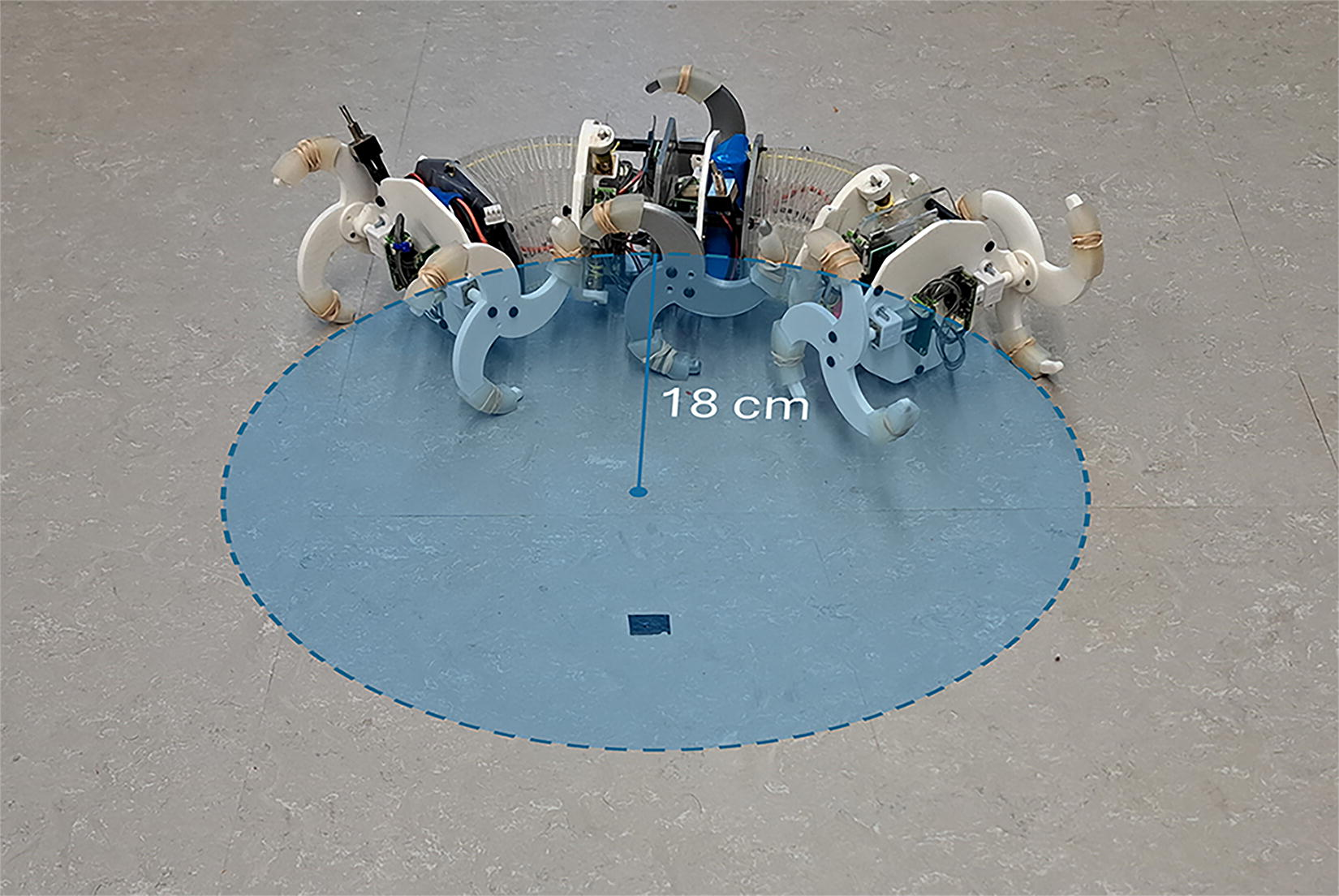
Minimum turning radius achieved by bending each module of the flexible spine by
Figure 8 shows the Lizard navigating through a maze by actuating its flexible spine to adapt to the shape of the walls. The maze consists of walls made with long sheets of corrugated cardboard. The sheets were formed into curved sections and bonded together with acrylic tape to create two walls. Five brackets were 3D-printed from PLA and fixed to the base of each wall. The walls were secured to the floor so that the entrance and exit of the tunnel were slightly wider than the distance between Lizard’s whegs. The curves in this type of narrow tunnel would be more challenging to navigate with a rigid body whegged robot with dimensions similar to Lizard. Lizard, in contrast, can deform its spine to adapt to the shape of the tunnel.

Lizard maneuvering through a narrow corridor by bending its flexible spine to conform to curves in the passageway.
Obstacle climbing
To test Lizard’s obstacle climbing performance, we set up a series of rectangular obstacles. Each obstacle consisted of a set of 300 × 300 mm × 6 mm plywood sheets stacked on top of each other and clamped to the surface of a table. We performed five trials on each obstacle, with heights ranging from 6 mm to 144 mm tall. We considered a trial successful if Lizard climbed the given obstacle in under 60 seconds without toppling over or getting stuck. Table 2 shows Lizard’s success rate while climbing obstacles ranging from 120 mm to 144 mm tall. Lizard demonstrated a 100% success rate on obstacles ranging from 6 to 126 mm tall; however, the success rate dropped to 80% on a 132 mm tall obstacle and 20% on a 138 mm obstacles. The failed trials were primarily caused by Lizard toppling over the side of the obstacle or high-centering and falling backward.
Lizard’s Success Rate While Climbing Rectangular Obstacles with Heights Ranging from 120 mm to 144 mm
A trial was considered successful if Lizard could climb onto the obstacle in under 60 seconds without tumbling over.
Figure 9 shows a demonstration of Lizard climbing a 132 mm (2.40 BL) tall obstacle in 46 seconds. To overcome the obstacle, we first bent Lizard’s front module upward to increase the reach of its whegs. This allowed the spokes on the front whegs to hook onto the top of the obstacle. With the front whegs on the obstacle, we straightened the first module and advanced toward the obstacle until the second pair of whegs met with the top of the obstacle. As the second pair of whegs pulled the end of the first module over the edge of the obstacle, we bent both modules downward to improve stability. With the front and middle whegs on top of the obstacle, we bent the second module upward to prevent the edge of the obstacle from interfering with the second module’s base plate and commanded Lizard to roll forward until both modules were on top of the obstacle.

A demonstration of Lizard climbing a 132 mm obstacle in 46 seconds by flexing the spine of the first module until the front whegs make contact with the top of the obstacle, then bending both modules downward to increase stability, and finally, bending the rear module upward until the back whegs were above the edge of the obstacle.
Speed on various terrains
To demonstrate Lizard’s ability to negotiate uneven terrains, we tested the robot on four increasingly difficult rough terrains—carpet, detritus, gravel, and thick grass. We conducted five trials with Lizard traveling 14 cm on each terrain. We filmed each trial and then used the Physlets Tracker video analysis tool to determine the robot’s speed during each trial. Table 3 shows Lizard’s average speed on each terrain. On the flat carpeted ground, the robot demonstrated a top speed of 39.20 cm/s, or 1.31 BL/s. As the difficulty of the terrain increased, Lizard’s speed went as low as 4.60 cm/s or 0.15 BL/s, which may still be acceptable for less time-sensitive applications.
Lizard’s Average Speed over Five Trials on Four Terrains
The terrains included carpet, detritus (i.e., packed soil, twigs, and sparse grass), gravel, and thick grass.
Whegged robot performance comparison
We present a more comprehensive comparison of performance characteristics for different whegged robots in Table 4. Here, BL indicates the length of the robot’s body and WL is the length of the wheg. Lizard notably has the smallest turning radius with the largest obstacle clearance. This suggests that Lizard will adapt well to complex environments such as cluttered spaces or uneven terrain with large obstacles.
Comparison of Performance Characteristics for Different Whegged Robots
CHOMP+ demonstration
Figure 10 demonstrates the CHOMP+ algorithm deployed in a cluttered environment with five obstacles scattered around an area between the robot’s initial position and the target. The entire system was implemented and controlled in MATLAB. An OptiTrack motion capture system tracked Lizard’s current pose with three markers attached to the front of the robot and provided additional information about the positions of the target and obstacles. During this test, the initial orientation of the path was taken from the robot’s initial pose, and the final orientation was set to
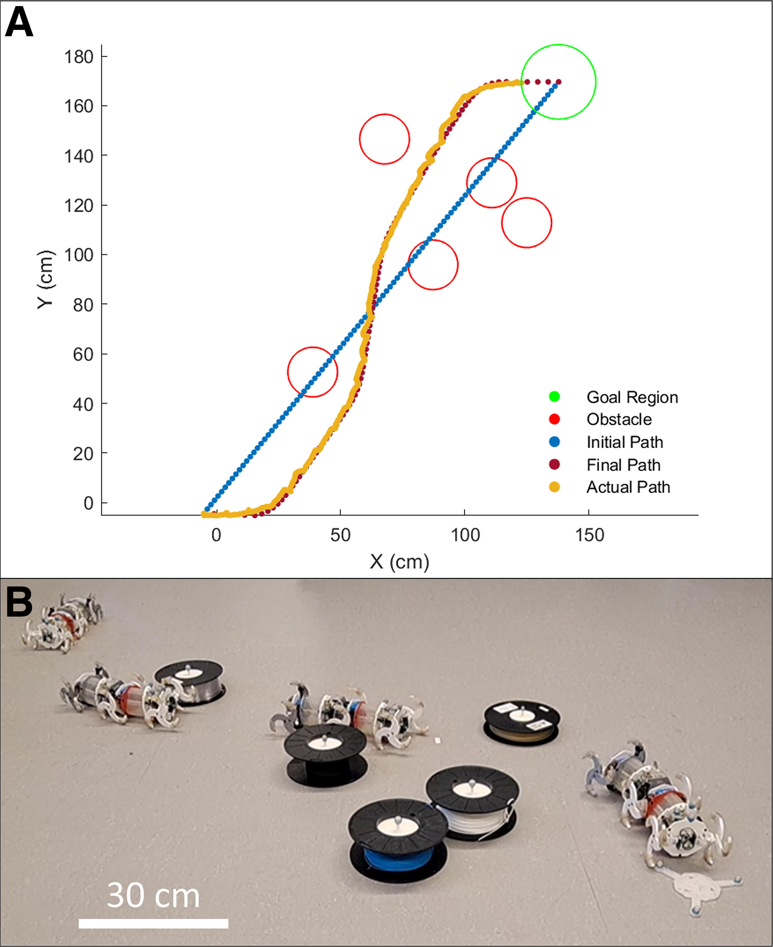
Demonstration of CHOMP+.
The path-following algorithm then drove Lizard along the determined path by periodically sampling the motion capture system for feedback on the robot’s pose before sending control inputs to Lizard’s onboard receivers. Given a feasible trajectory, the line-of-sight (LOS) algorithm
27
used the following procedure to track the target path:
Sample the motion capture system to determine the robot’s current pose. Find the index of the closest waypoint. Add a small buffer to the index of the closest point to get the reference point index. Use the difference between the robot’s current position and the reference point to generate the LOS vector. Using a simple PD controller, calculate a new spine configuration to correct for the error between the robot’s current heading and the LOS vector.
Lizard successfully tracked the path until it reached the goal region with a
Conclusion
This work detailed the design and assembly of Lizard, a novel wirelessly controlled mobile robot with six whegs coupled to two flexible origami spine modules. Each wheg featured three
Footnotes
Authors’ Contributions
T.V.J.: Conceptualization, software, investigation, writing—original draft, and writing—review and editing. G.G.C.: Investigation, formal analysis, writing—original draft, and writing—review and editing. A.G.S.: Investigation, visualization, and writing—original draft. Y.S.: Software and writing—original draft. C.D.O.: conceptualization, funding acquisition, and writing—review and editing.
Disclaimer
Any opinions, findings, conclusions, or recommendations expressed in this material are those of the authors and do not necessarily reflect the views of the National Science Foundation (NSF).
Author Disclosure Statement
The authors declare that they have no conflict of interest.
Funding Information
This material is based upon work partially supported by the NSF under Award No. CMMI-1752195, DGE-1922761, and CNS-2228652.