
Abstract
Controlled grasping using soft robotic grippers is a significant challenge that hinders their deployment in unstructured environments. This work presents a directly three-dimensional (3D) printed soft pneumatic finger that involves separate chambers for soft pneumatic-based control, actuation, and sensing (SoPCAS) simultaneously. The actuation chamber of the finger is designed as a pneumatic network that expands upon pressurization, and its sensing chamber is designed as a thin wall soft pneumatic chamber embedded with a solid air pressure sensor that measures the volume change (i.e., pressure change) when the finger is in contact with its environment. The soft finger is 3D printed using a commercially available thermoplastic polyurethane (TPU) and a fused deposition modeling (FDM) 3D printer. The SoPCAS finger is characterized in terms of repeatability, hysteresis, force–pressure relationship, and stability (i.e., airtightness). Two SoPCAS fingers are used to develop a gripper that highlights the usage of the actuation and sensing components in real-time closed-loop feedback grasping applications using a simple and manually tuned proportional-integral (PI) controller. The gripper demonstrates successful grasping of various objects with different weights, shapes, textures, and stiffnesses, making SoPCAS finger a promising candidate for applications requiring real-time force/pressure control in highly dynamic and unstructured environments.
Introduction
Soft robots have widely attracted researchers given their potential in achieving safe, adaptive, and precise interaction with their environment. 1 Compared to conventional rigid robotic structures, soft robots are made of compliant and flexible materials that have inherent safety and compliance. 2 These properties offer substantial advantages to soft robots especially when it comes to developing robotic grippers that are suitable for applications requiring safe human–robot interaction and grasping and manipulating objects with different weights, shapes, textures, and stiffnesses.3–5 Nonetheless, the inherent compliance of soft robots poses considerable difficulties and challenges in controlling their fully deformable structures, limiting their applicability in areas where accurate and precise control is required, such as grasping fragile objects, due to their infinite degrees of freedom and highly nonlinear dynamics.6–8
Soft pneumatic actuation represents the most popular approach for actuating soft robotic structures. 3 With its design simplicity and ease of fabrication, Pneumatic Networks (PneuNets) stands out among the various methods used for pneumatic actuation of soft bodies. PneuNets-based actuation is achieved through a series of small chambers on top of a base that has a relatively higher stiffness to generate complex motions such as bending, twisting, elongation, or a combination of those.8–10 Given these characteristics, the PneuNets design has been widely adopted for soft robotic grippers10–16 and has seen extensive studies covering its modelling,11,17–19 optimization,12,20 and structural enhancements that improve its performance.13,16,19
Real-time closed-loop feedback control of soft robotic grippers can be realized through the development of novel sensing approaches that can be directly integrated with the soft body of the grippers without affecting their inherent compliance, and thus without altering their behavior. 6 Several approaches have been considered to sensorize soft grippers such as embedding soft resistive strain sensors inside the soft finger structure,21,22 attaching soft and stretchable sensors, such as soft optical fibers and liquid metal sensory skins, on specific areas of the soft fingers,23,24 designing soft fingers that accommodate rigid sensors, such as cameras, in their structure,25,26 and externally sensing the deformable fingers with camera sensors separated from the finger body.27,28 Equipping PneuNets structures with sensing capabilities through these techniques have been implemented by embedding resistive sensors18,21,29,30 or optical fibers 14 into the body of the soft actuator.
Despite this variety in soft-sensing technologies and approaches, integrating such sensors with the body of soft fingers or grippers remain a challenge due to several reasons. First, when soft sensors are used, their signals should continuously reflect the state of the soft body, whether they are embedded inside it or attached to it, which necessitates distributing them along the whole soft body such that they are subject to the same loads and deformations. Second, the already proposed soft sensors involve complex and laborious fabrication process and steps that limit the mass production of sensors with similar characteristics.
Third, most of such sensors have undesirable characteristics, such as nonlinear response and hysteresis, and drift over time (i.e., lack of stability).6,31 Fourth, in the case of conventional rigid sensors, they require innovative design approaches to prevent them from altering the behavior the soft body or gripper due to the difference in compliance between the sensing element and the soft body and, consequently, obtain uninterrupted and accurate information about the state of the grippers.9,28
Compared to the already proposed soft-sensing technologies and approaches, soft pneumatic chambers represent an effective and attractive approach for endowing soft robotic structures with viable sensing capabilities due to their fast response, reliability, repeatability, stability over time, negligible hysteresis, and very low power consumption.31,32 These chambers are usually realized through the combination of solid pressure sensors with a hollow chamber such that any volume change inside the chamber is reflected as a pressure change following Boyle's law at constant temperature.8,31 Previous works utilized the concept of soft pneumatic chambers for several goals including human gait monitoring, 33 force estimation,34,35 haptic feedback,32,36 and control of robotic grippers remotely through wearable gloves.32,37
In the context of soft grippers and fingers, these chambers have been integrated with tendon-driven grippers of different designs through monolithically three-dimensional (3D) printed structures to successfully enable closed-loop position 38 and force control. 39 For PneuNets actuators, pneumatic sensing chambers that can be directly manufactured with the actuator body were explored to measure the bending angle. 40 However, the presented design may not be suitable for controlled grasping given that the sensing chamber internally deforms with the actuator.
In this work, we present the soft pneumatic-based control, actuation, and sensing (SoPCAS) finger, a monolithic sensorized 3D printed soft pneumatic finger that is composed of separate pneumatic actuation and sensing chambers. The actuation chambers are developed based on PneuNets, whereas the sensing chamber is designed as a soft pneumatic deformable chamber embedded with a solid pressure sensor that measures internal volume change when it is deflected. The actuation and sensing chambers are attached together and separated by a wall in a single finger design that can be monolithically 3D printed, as shown in Figure 1. The sensing chamber was characterized to study the relationship between its deformation and the acquired signal from the solid pressure sensor.

The 3D printed soft fingers and gripper with actuation and sensing capabilities:
A simple two-finger gripper design was developed based on two prototypes of SoPCAS finger to validate the sensing chamber capability and performance in achieving closed-loop feedback control. A proportional-integral (PI) controller was successfully implemented to control the input pressure that actuates the gripper using the feedback signal from the pressure sensors on the pneumatic chambers in real time, thus achieving real-time pressure/force control. The gripper was capable of grasping several objects with different properties in terms of size, shape, weight, and stiffness. Figure 1 illustrates the 3D computer-aided design (CAD) model of SoPCAS highlighting the actuation and sensing chambers, the monolithic 3D printed finger prototype, and the two-finger gripper with the pressure sensors where one sensor was attached to each sensing chamber.
Overall, the contributions of this work can be summarized as follows:
Design and prototyping of SoPCAS finger: a monolithic 3D printed soft finger with separate pneumatic chambers for simultaneous actuation and sensing for real-time pressure/force control. Experimental characterization and performance assessment of the finger prototype-sensing chamber with analog pressure sensors. Real-time closed-loop controlled grasping based on the feedback signals from the sensing chambers embedded in a SoPCAS-based gripper.
Finger Design and Prototype
The 3D CAD models of the finger and gripper were developed using SolidWorks (Dassault Systémes SE) modeling software. Finite Element Method (FEM) simulations were carried out using Ansys Mechanical (Ansys, Inc.) to study the behavior of the finger. Higher-order tetrahedral elements were used to mesh the soft finger and the rigid cylinder with an element size of 2.5 mm, and a fixed support was imposed at the backside base of the finger (i.e., on the face of the hole of input pressure to the actuation chambers) and the sides of the cylinder for the contact simulations in each simulation. Normal pressure was applied on all the internal faces of the actuation chamber. Self-contact frictional pairs were applied between the outer wall of the actuation chamber since they come into contact upon deformation, while a frictional contact pair was applied between the finger (i.e., contact) and the rigid cylinder (i.e., target). The hyperelastic model presented in Tawk et al. 38 was used to model the NinjaFlex material behavior.
The finger prototype was manufactured using thermoplastic polyurethane (TPU) material known commercially as NinjaFlex (NinjaTek) and an open-source fused deposition modeling (FDM) 3D printer known commercially as FlashForge Creator Pro (FlashForge Corporation). The same 3D printing parameters for the slicing software (Simplify3D, LLC) presented in Tawk et al. 38 were used to manufacture the fingers. Figure 2 shows the finger design in different views along with the dimensions of the finger. The pressure sensor hole is located inside the thick part of the sensing chamber with 100% infill to eliminate any interaction between the solid pressure sensor and the deformable part of the sensing chamber. On the other hand, the actuation chambers contain a hole that extends to the backside of the finger to connect an inlet pressure tube.

Design and dimensions of the proposed soft finger showing its
Figure 3a highlights the FEM simulation results of the finger behavior and the bending angle under 50 kPa of input pressure for different number of PneuNets. The chosen finger design incorporates six PneuNets as they provide a bending angle larger than 90° within 50 kPa of pressurized input air. Nonetheless, the finger design can be tailored to include less or more PneuNets depending on the application. The hollow region inside each actuation chamber extends to 1 mm, and a distance of the same length separates each network. A bottom channel with a height of 1.9 mm connects the PneuNets with each other such that the pressurized air reaches all networks. The bottom wall thickness that covers the bottom channel is chosen as 1.4 mm.
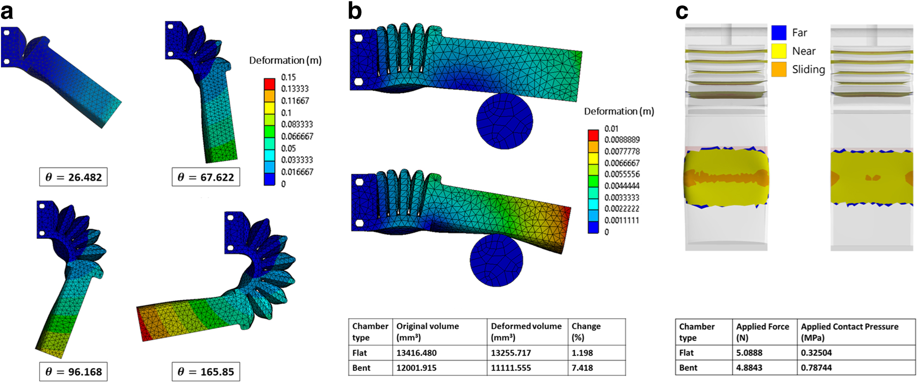
Selecting the wall thickness surrounding the actuation chambers is faced by several design limitations and considerations. In a single PneuNet, lower wall thickness has been shown to cause more deformation for the same input pressure. 20 However, high input pressure may damage walls with small thicknesses. Additionally, the quality of the walls is generally affected by the printing parameters and the printer used. Given the aforementioned trade-offs and design considerations, a wall thickness of 0.8 mm across the finger is chosen for the PneuNets walls as this thickness of 0.8 mm has been shown to result in airtight soft pneumatic structures when using NinjaFlex with an FDM 3D printer. 39
The soft pneumatic sensing chamber is hollow from the inside with a pressure sensor attached to it. The sensor measures the changes in the pressure of the hollow chamber when the finger comes into contact with an object as the chamber has a thin frontal wall that deforms during the contact. Moreover, the final design of the chamber has a curved contact surface designed to enhance its deformation when the finger is in contact with an object.
Figure 3b compares the simulation results of the proposed finger design against the same design with a flat sensing chamber when pressing a cylinder under 50 kPa of pressurized actuation chamber. The curved sensing chamber causes a volume change that is roughly six times the change seen in the flat chamber. The wall thickness of the sensing chamber is chosen at 1 mm to generate the required deformation during the grasping process. Higher structural deformation causes larger changes in the pressure sensor readings, which may lead to provide higher sensitivity about the grasping scene data and information. The internal height of the sensing chamber ranges between 6.9 mm on its sides and 9.9 mm in its middle point when seen from front. In other words, the frontal cross section of the sensing chamber is designed as an ellipse with a semiminor axis radius of 3 mm (i.e.,
The actuation and sensing chambers are connected with a wall that separates them to eliminate any volume change in the sensing chamber resulting from the bending of the actuation chambers. The wall thickness between the chambers is chosen to be 3.8 mm. Figure 4 shows experimental data for the effect of the input pressure on the sensing chamber pressure in the absence of contact. The signal was acquired after pressurizing the actuation chamber and allowing the pressure to drop after actuation to acquire the sensing chamber signal under variable input pressure, indicating the minimal effect the actuation pressure has on the sensing chamber pressure.
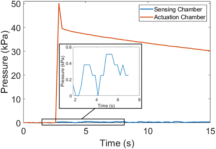
Response of the sensing chamber pressure sensor when the actuation chamber is pressurized without contact.
The length of the full finger is 80 mm where the sensing chamber takes 50.4 mm out of it. The width of the finger is 30 mm, where a wall of 1 mm at each side covers the chambers that extend internally by 28 mm. Developing PneuNets-based actuators that allow actuating part of the internal chambers have been proposed and studied in Liu et al., 16 showing enhanced performance compared to the conventional PneuNets design in many aspects. In other words, aside from the sensing capability, our design brings the benefits of larger contact area in the pinch-grasping mode shown in Liu et al., 16 given that the sensing chamber is not actuated. The contact area is further enhanced by the bent sensing chamber as shown in Figure 3c, achieving a comparable applied force with less than half the contact pressure compared to the flat sensing chamber.
Sensing Chamber Characterization
The characteristics of the sensing chamber in the proposed design strongly influence its performance in grasping applications. For instance, the acquired pressure signal may jeopardize the grasping process if air is leaking from the chamber under deformation. Therefore, in this section, the sensing chamber was characterized to assess its behavior and performance in terms of repeatability, stability (i.e., drift over time resulting from airtightness level), hysteresis, and pressure–force relationship to confirm the reliability and validity of using SoPCAS finger with embedded pneumatic actuation and sensing chambers for developing reliable soft robotic grippers that can be accurately controlled using the sensing chamber signals based on the gripper grasping state.
The repeatability, stability, and hysteresis experiments were performed using a linear actuator (L16-50-63-6-R; Actuonix Motion Devices, Inc.) to deflect the sensing chamber (i.e., causing a pressure change). A pressure sensor (ABPDANT015PGAA5; Honeywell International, Inc.) was directly glued to the sensing chamber to measure its internal pressure changes. An Arduino Mega 2560 Rev3 micro-controller board was used to record the pressure data obtained from the solid pressure sensors and to control the linear actuator for the characterization experiments. The linear actuator was actuated using pulse-width modulation (PWM) signals, whereas the pressure sensor readings were acquired as analog input signals. Finally, the force–pressure comparison experiment involved acquiring the signal of a force sensor (Dual-Range Force Sensor; Vernier Software & Technology) that was pressed randomly against the sensing chamber to show that both the sensing chamber and the force sensor have similar characteristic curves.
Repeatability
The linear actuator pressed and released the sensing chamber 100 times over a period of 10 minutes, while the pressure sensor readings of the sensing chamber were recorded. The setpoint of the linear actuator was fixed (i.e., same linear stroke in each cycle) during each cycle such that the sensing chamber exhibits the same deformation every cycle. Figure 5a shows that the sensor provides consistent and reliable pressure signal with minimal differences. Moreover, the sensing chamber quickly recovers its initial state as the sensor readings consistently return to the starting pressure, confirming that the sensing chamber is airtight.

Hysteresis
In this experiment, the input to the linear actuator was ramped up and down by one millimeter in each step to press or release the sensing chamber to assess it in term of the hysteresis. The experiment was repeated five times to corroborate the obtained results. Figure 5b demonstrates that the chamber exhibits negligible hysteresis. Such a result facilitates the process of developing accurate control systems using SoPCAS finger as hysteresis modelling is not required to achieve accurate and precise control.
Drift over time
The sensing chamber was pressed for 10 minutes caused by the linear actuator to check the stability of the acquired signal (i.e., airtightness of the chamber). As shown in Figure 5c, the pressure loss was limited to around 2.5% of the starting pressure as it dropped from 10.07 to 9.82 kPa, confirming the stability and airtightness of the printed chamber. The minor change in pressure can be attributed to the overshoot of the linear motor at beginning which resulted in an increased pressure initially. Combining this result with what was concluded from Figure 5a and b, these features reflect the reliability of utilizing the proposed finger design with actuation and sensing chambers for grasping applications.
Force–pressure relationship
In this part, an arbitrary force was applied on the sensing chamber using the force sensor to compare the pressure and force readings and assess the potential of using the pressure sensors in force control applications. Figure 5d shows that the force sensor and the sensing chamber have similar characteristic curves. In other words, the sensing chambers follow the behavior of the force sensor, proving that it can be used as a reliable pressure sensor in a gripper to achieve pressure/force control.
Controlled Grasping Experiments
SoPCAS fingers were used to develop a simple two-finger gripper to demonstrate the potential in achieving closed-loop control in grasping applications for objects with varied properties.
Experimental setup
A pressure regulator (ITV2031-21F2S5; SMC Corporation) was connected to an air compressor to supply the actuation chambers of the gripper fingers with compressed air. The regulated pressure output tube was connected to an inlet tube that was glued to the hole inside the actuation chambers. The input signal to the pressure regulator was controlled using the feedback signal from the sensing chambers. A data-acquisition (DAQ) card (PCI 6221; National Instruments) controlled using Simulink Real-Time tool in MATLAB (MathWorks) software was used to directly operate the system. Figure 6 shows the components and the corresponding flow of operations of the experimental setup.

Experimental setup components for the gripper control experiment.
The experiments involved several test objects that included a small paper cup, a hollow cylindrical aluminum part, a mango fruit, a soft sponge, a single grape, and a 400-point breadboard. Each object was experimentally tested to determine a preset reference signal (i.e., setpoint) that can act as a reference input target pressure.
Gripper control
The average pressure value obtained from both sensing chambers was used as the feedback signal. A PI controller was manually tuned (i.e., trial and error) to control the soft gripper. A low-pass filter with a cut-off frequency of 10 rad/second was used to filter the noisy signals from each sensor before computing their average. Figure 7 shows the block diagram of the described closed-loop feedback control system.

Block diagram of the closed-loop feedback control system where u indicates the control signal, pa is the input pressure to the actuation chambers, P is the readings from the sensing chambers, p is the average of these readings, and e is the error between p and the sensing chamber pressure setpoint
The manual tuning process of the PI controller revealed that choosing the controller constants
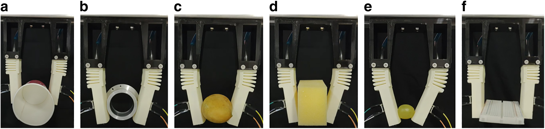
Gripper operations with successful closed-loop control during the stable grasping of the
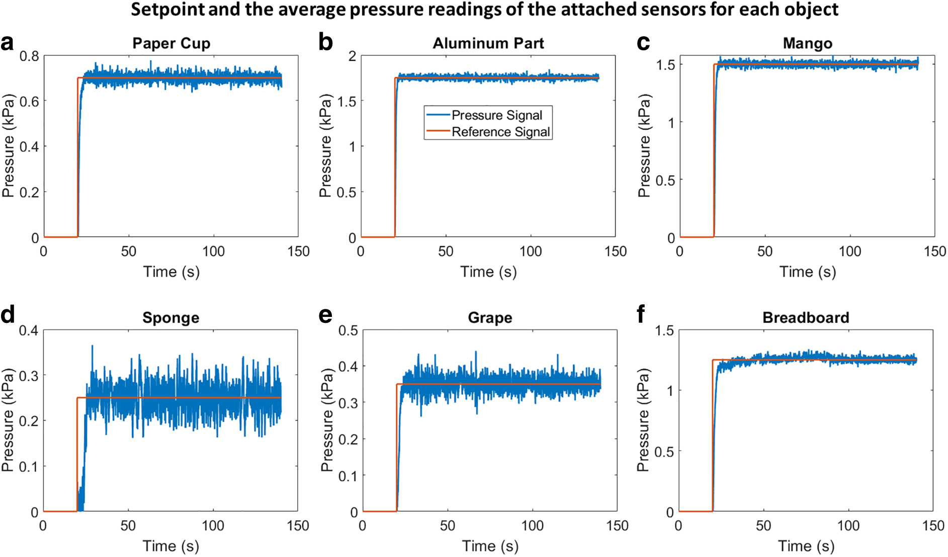
Average pressure readings of the two pressure sensors caused by the deformation of the sensing chambers during the grasping of the
Discussion
The presented finger design seamlessly combines pneumatic sensing chambers with PneuNets actuation chambers in a single monolithic structure that can be rapidly manufactured with low-cost 3D printing technology. The sensing chamber has undergone several tests that successfully confirmed its reliability and readiness for constructing soft robotic grippers that use the finger in grasping application.
The developed gripper utilized the proposed SoPCAS finger design and analogue pressure sensors to enable stable grasping of different objects using solely pneumatic-based tools for both actuation and sensing with closed-loop control that guarantees the operational safety during the grasping process regardless of the object properties. The results demonstrate that pneumatic sensing chambers present an effective and simple approach to sensorize pneumatically actuated soft fingers that adopt PneuNets design. We believe that our current finger design can be scaled to construct grippers that can suit applications with various object properties as long as the chambers are airtight.
Conclusion and Future Work
This work presents a novel design for a monolithic soft pneumatic finger that combines pneumatic-based actuation and sensing chambers in a single 3D printed structure to enable closed-loop control of grasping operations. The actuation chambers were designed with six PneuNets that expand when compressed air is supplied. On the other hand, the pneumatic soft sensing chamber uses pressure sensors to measure the pressure changes inside the chamber when it is subjected to a load. The finger prototype was fabricated from the hyperelastic NinjaFlex 3D printed material. Based on several characterization tests and experiments that were performed on the sensing chamber, the finger prototype exhibits an airtight and reliable structure when printed with the chosen design and printing parameters, indicating that it can be readily used for the intended application. Subsequently, a two-fingered gripper was developed to enable the controlled grasping of several objects. A real-time PI controller was successfully used to actuate the actuation chambers of the finger. The average readings of the pressure inside both sensing chambers was used as feedback signal that was compared with a preset reference pressure, and the error was used as an input to the controller to produce a PWM signal that was fed into the pressure regulator connected to the actuation chamber. Stable grasping of six objects with high variations in their properties using the developed gripper was shown to confirm the effectiveness of the proposed approaches in achieving closed-loop control of the soft pneumatic gripper.
In the future, we plan to optimize the design parameters of the SoPCAS finger design and utilize such fingers in grippers with variable workspace that can accommodate more objects. Moreover, the sensing chamber can be further utilized to attach more sensors and enhance its capability by changing the design parameters to include extra sensors. In such scenarios, machine-learning techniques may provide the necessary framework for processing the information of the grasping scene activity to deliver the desired performance.
Footnotes
Acknowledgment
The authors would like to thank Dr. Mohammad I. Awad (Khalifa University) for his help in performing the control experiments.
Author Disclosure Statement
No competing financial interests exist.
Funding Information
This publication is based upon work supported by the Khalifa University of Science and Technology under Award numbers FSU-2021-019 and RC1-2018-KUCARS and the University of Wollongong in Dubai.
Abbreviations Used
References
Supplementary Material
Please find the following supplemental material available below.
For Open Access articles published under a Creative Commons License, all supplemental material carries the same license as the article it is associated with.
For non-Open Access articles published, all supplemental material carries a non-exclusive license, and permission requests for re-use of supplemental material or any part of supplemental material shall be sent directly to the copyright owner as specified in the copyright notice associated with the article.