
Abstract
Introduction
Furthermore, the results in the available literature regarding subablative Er:YAG laser irradiation as a method to increase enamel acid resistance for caries prevention have been contradictory. 15,16 One previous study evaluated enamel morphological changes and acid resistance after subablative Er:YAG laser irradiation. Although the acid resistance was not increased, scanning electron microscopy (SEM) analysis on the enamel surface showed craters and cracks, 17 which may be sites of high risk sites for bacterial accumulation. In addition, a massive demineralization along the cracks has been reported. 15 However, additional research regarding the undesirable effects of Er:YAG laser irradiation is needed.
Recently, more attention has been focused on the application of atomic force microscopy (AFM) in dental research 18 –21 because of its applications in the exploration of biomaterial surfaces. Furthermore, it is useful because it has a higher resolution than SEM, and a three-dimensional image compared with the two-dimensional image of a sample observed with SEM. The use of both microscopic analyses may improve the observation of morphological changes of the enamel, resulting in a synergism achieved by the advantages of each technique.
Regarding enamel structural changes associated with Er:YAG laser irradiation, alterations to apatitic inorganic component of tooth enamel, 22 as well as differences in the calcium/phosphorus (Ca/P) ratio, 13 and significant laser-induced reduction of carbonate and modification of organic material content, have been reported. 23
Therefore, the aim of the present study was to evaluate, using AFM and SEM, the morphological changes of the enamel surface after irradiation with the Er:YAG laser, and the structural changes through the weight percentages (wt%) of Ca, P, oxygen (O) and chlorine (Cl) in the resulting craters and periphery area with energy dispersive X-ray spectroscopy (EDS).
Materials and Methods
Tooth selection and sample preparation
The study protocol was reviewed and approved by the Research and Ethics Committee at the Autonomous University of the State of Mexico (UAEM). All subjects enrolled in this research signed a consent form. Five unerupted permanent third molar teeth extracted from two patients for therapeutic reasons were stored in a 0.1 (wt/vol) thymol solution at 4°C until the experiment was performed. The crown was separated from the root in each tooth using a diamond disc (BesQual, NewYork, NY) mounted on a low-speed motor (Brasseler, Savannah, GA) under distilled water irrigation to prevent dehydration. The crown was fixed to a glass slide with thermoplasticized epoxy resin (Allied, Rancho Dominguez, CA).
Afterward, a diamond wheel (South Bay Technology, Inc., San Clemente, CA) mounted on a cutter (South Bay Technology, Inc.) was employed to obtain the samples under constant irrigation. For the AFM evaluation, an unerupted permanent third molar was vertically crosscut in the buccolingual direction, and four samples measuring 8 mm wide x 5 mm high were obtained (one for each group). The samples were fixed with thermoplastic cement (Buehler, Lake Bluff, IL) to AFM steel mounting discs (SPI Supplies, West Chester, PA). All of the samples were polished with a MetaServ® 2000 polisher machine (Buehler), using diamond lapping film with grain sizes of 35, 30, 15, 9, 6, 3, 1, 0.5, 0.25, and 0.1 μm under constant water irrigation. Only two samples (Groups II and III) were further polished after laser irradiation.
For the EDS and SEM analysis, the occlusal surfaces from four unerupted permanent third molar teeth were vertically crosscut in the buccolingual and mesiodistal directions. Twelve samples per molar were obtained (three for each group), measuring 1.5 mm wide x 2 mm in length. A total of 48 samples were obtained (twelve samples per group) (Fig. 1).
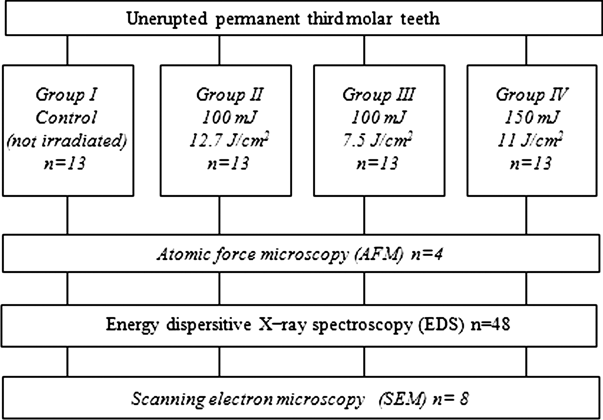
Experimental design.
Finally, all of the samples were rinsed with deionized water and dried at room temperature for AFM, EDS, and SEM evaluation.
Er:YAG laser irradiation
An Er:YAG laser system (Lumenis OPUS DUO™ Er: YAG + CO2, Yokneam, Israel) was used to irradiate the samples. The main experimental parameters of the laser during the study were as follows: wavelength fixed at 2.94 μm, energy pulse from 100 to 150 mJ, frequency of 10 Hz, pulse duration of 250-400 μsec, and an exit tip diameter from 1.0 to 1.3 mm. Fifty-two enamel samples were divided into four groups (n = 13) (Table 1).
Energy levels were calibrated using the calipers of the equipment, and the energy delivered was measured periodically with a power meter (LaserMate-P, Coherent Co., Santa Clara, CA). The irradiation was manually performed in one direction such that the tips were smoothly scanned perpendicularly to the samples' enamel surface while distilled water was sprayed (5.0 mL/min) to reduce heating. Each sample was irradiated only once during 18 sec, while the tip-sample distance was kept at a fixed position of 1 mm. A sheet of stainless steel (23 mm x 5 mm x 0.5 mm) was fixed to the top of the laser handpiece to perform this task. At that tip-sample distance, the exit tip and the laser beam had the same diameter, as corroborated with a laminated infrared sensor screen (Lumitek International, Inc., Ijamsville, MD).
AFM
AFM images of four samples (three irradiated and one control) were recorded using a Digital Instruments Multimode NanoScope IIIa (Digital Instruments, Plainview, NY) operating in contact mode and using a standard Si3N4 tip.
EDS
Forty-eight samples (12 per group) were dried at room temperature and attached to a testing ring with an adhesive carbon tape (SPI Supplies, West Chester, PA) to determine the weight percentage (wt%) of Ca, P, O and Cl in the resulting craters and their periphery by EDS (ThermoNoran Superdry, Thermo Scientific, Waltham, MA), under the following parameters: 15.0 KeV and 100 sec livetime. By this method, 12 points were performed per sample.
SEM
Eight samples (two per group) were attached to a testing ring using an adhesive carbon paper and were gold-coated (Vacuum Evaporator JEOL, Tokyo, Japan) for observation using the scanning electron microscope (JSM-5300, JEOL).
Statistical analysis
All data were analyzed using the SPSS 13.0 statistical package for Windows (SPSS Inc., Chicago, IL). The measurements were analyzed using the Kolmogorov–Smirnov test at a p ≤ 0.05 level of significance to assess the distribution of the data. The Kruskal–Wallis and Mann–Whitney U tests were used with a level of significance of p ≤ 0.05.
Results
AFM surface analysis
Group I control (no laser irradiation)
AFM images show the typical enamel surface of the polished sample (Fig. 2a and b).
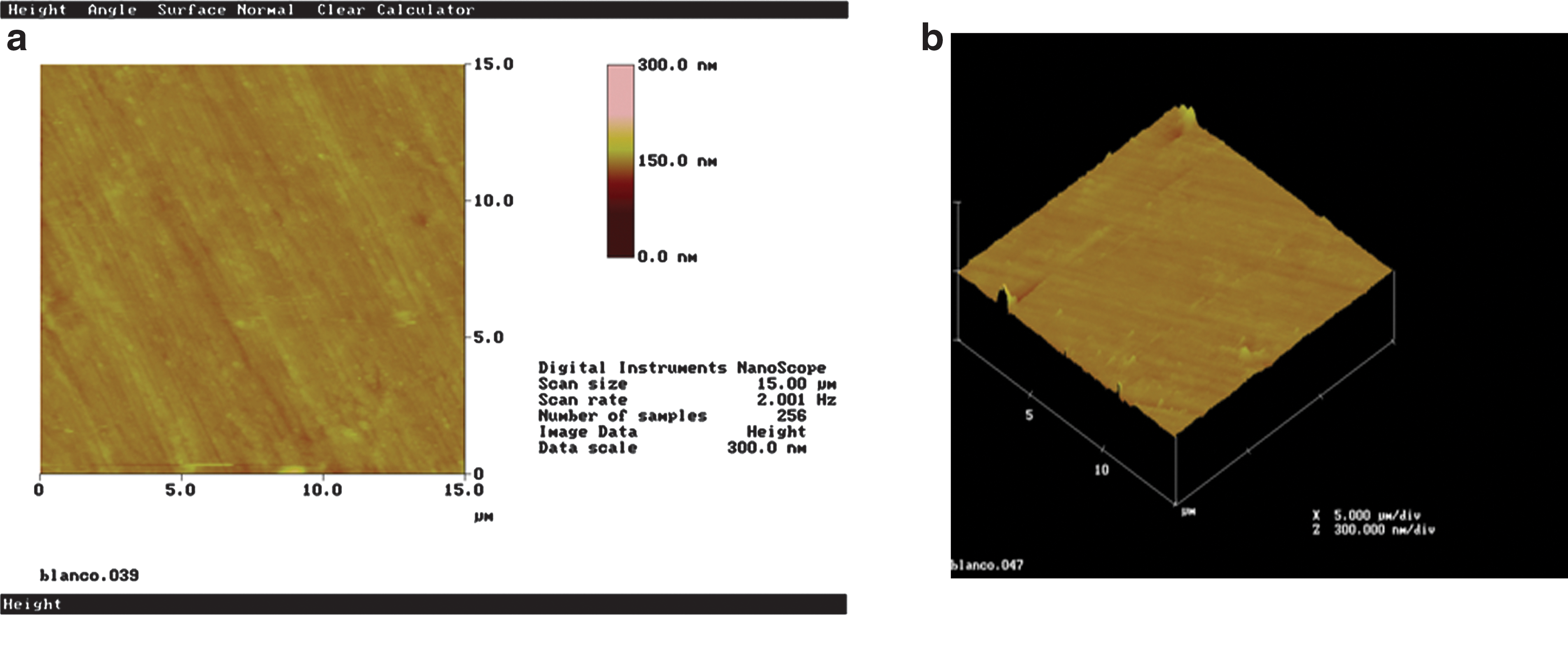
Tapping mode AFM images of the control group: (
Group II
A crack (∼250 nm deep × 2.58 μm wide × 20 μm long) can be easily observed on the enamel surface; it is marked by two red triangles or cursors. (Fig. 3a and b).
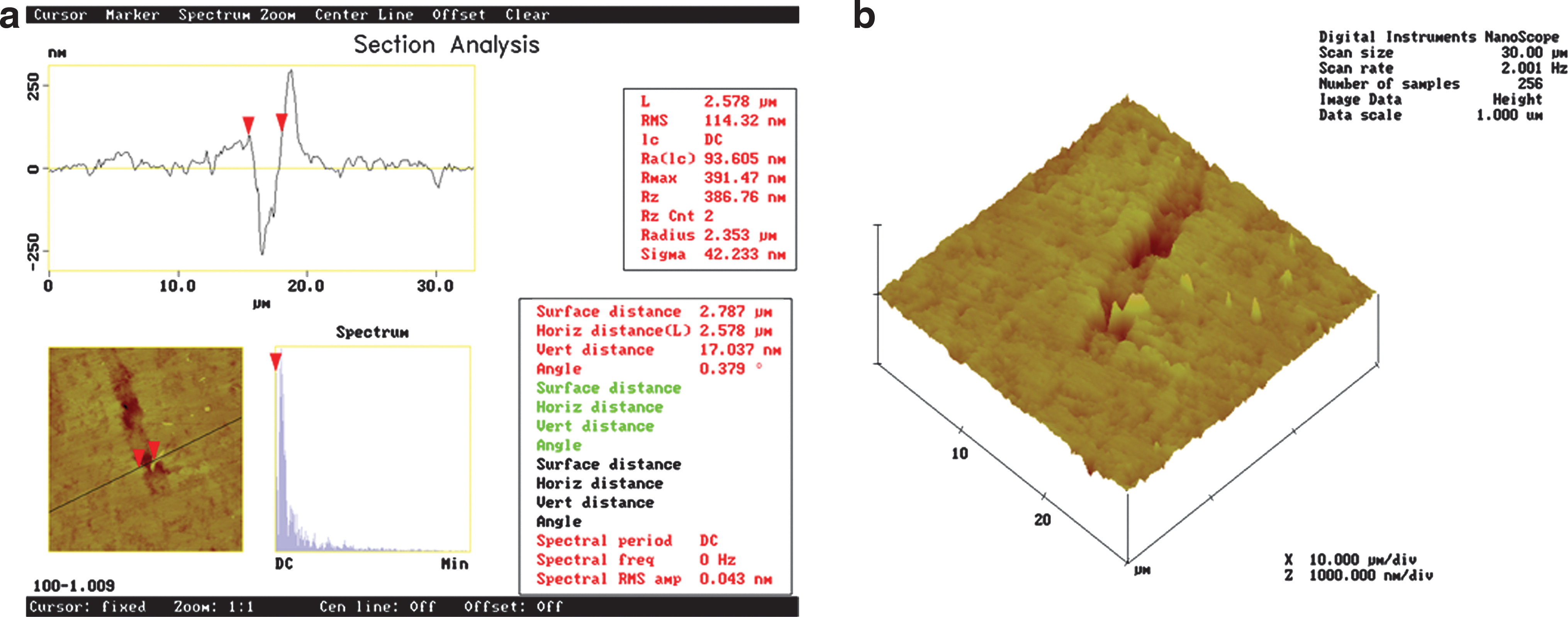
AFM images of 30 × 30 μm from the Er:YAG laser-irradiated enamel at 100 mJ/10 Hz, 12.7 J/cm2 after polishing. Section analysis and (
Group III
There is an S-shaped crack across the AFM top view image. The marked segment between the red cursors is ∼500 nm deep × 2.22 μm wide × 20 μm long (Fig. 4a). The 3-D expression shows a very rough surface characterized by ridges and grooves (Fig. 4b).
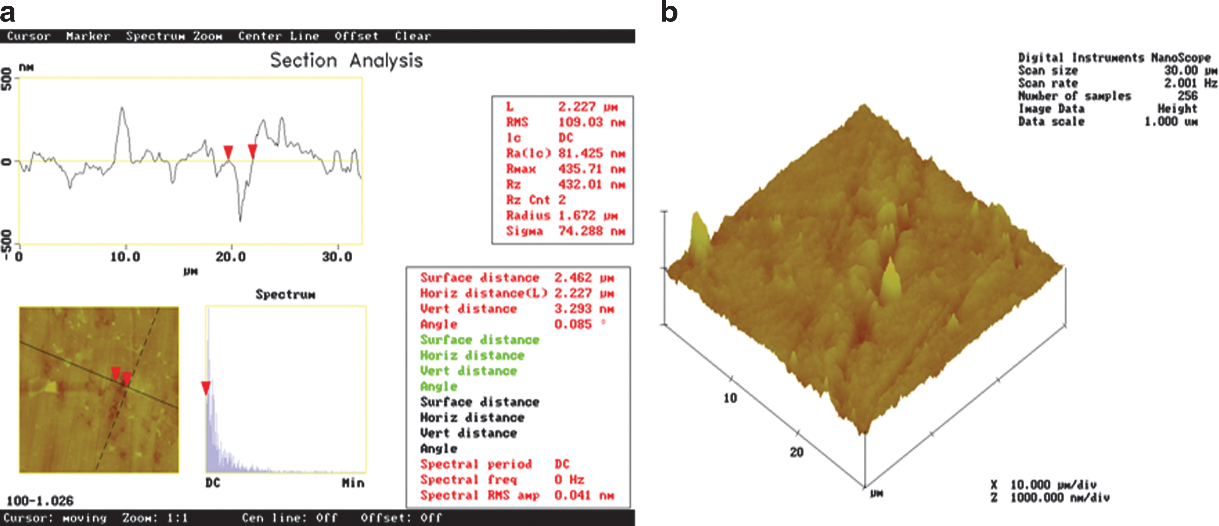
AFM images after Er:YAG laser irradiation at 100 mJ/10 Hz, 7.5 J/cm2, and polishing. Section analysis and (
Group IV
The AFM top view image shows a curved crack ∼750 nm deep × 5.37 μm wide × 20 μm long, in an unpolished sample after enamel irradiation (Fig. 5a). The 3-D figure shows the stacking of removed material at both sides of the crack, caused by laser irradiation (Fig. 5b). The area inside the fissure shows an evident rough surface (Fig. 5c).
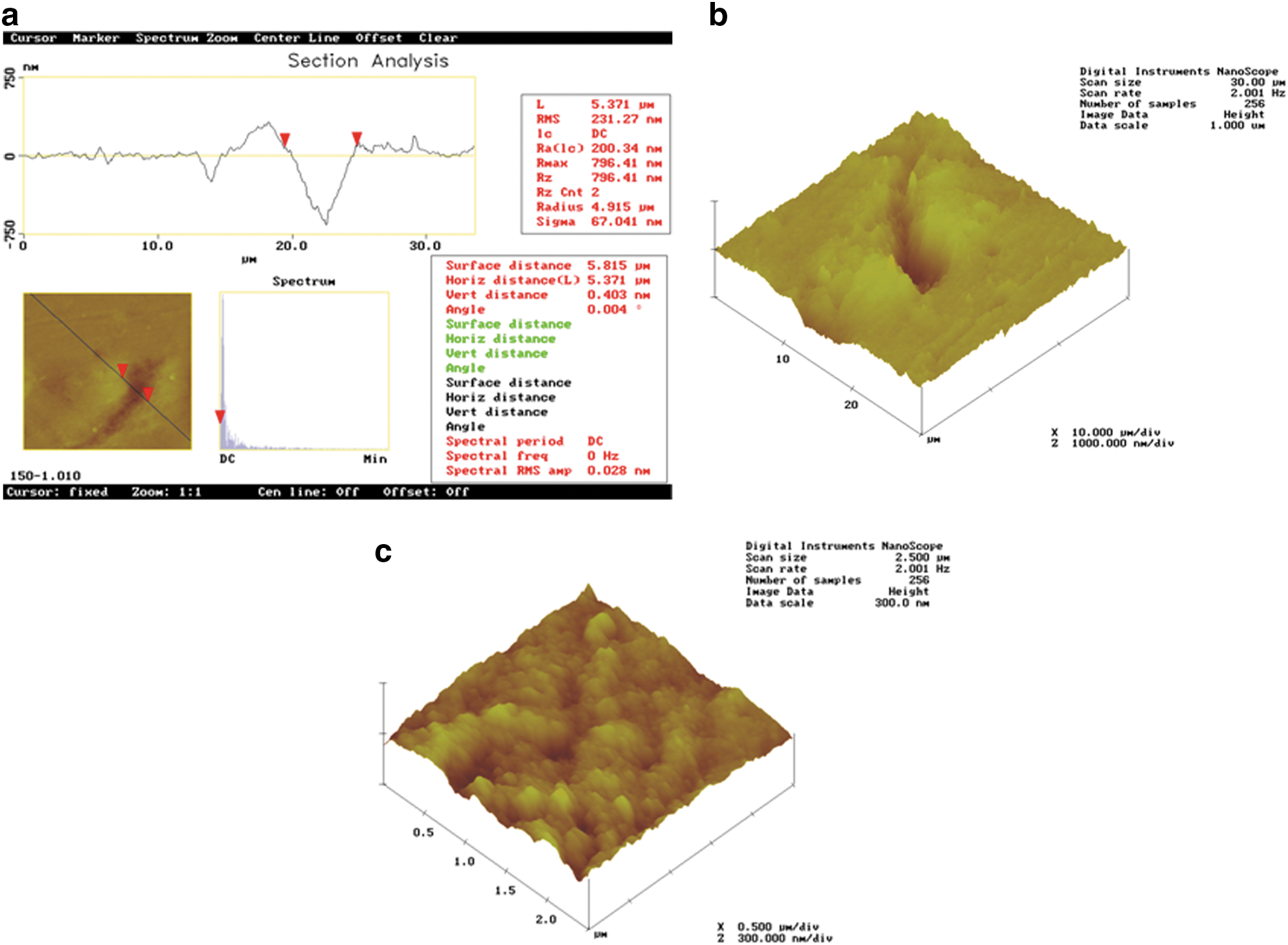
(
EDS evaluation
The experimental data obtained by EDS for all groups, in the crater and periphery with respect to wt% of Ca, P, O and Cl, are presented in Table 2. When the Kruskal–Wallis test was applied, statistically significant differences were obtained for Ca (p = 0.001), P (p = 0.004) and Cl (p = 0.003). According to the Mann–Whitney U test, the following statistically significant differences were found. For Ca, Groups III and IV demonstrated values in the crater and the periphery, respectively, that differed from what was found in all of the groups and areas studied. Additionally, in the periphery, Group III showed the lowest wt% of Ca when compared with the control group. Regarding P, the periphery of Group IV had the lowest value among all of the groups and study areas. The results obtained for Cl revealed differences in the crater when comparing the different groups and areas.
Groups with different letters are significantly different (p ≤ 0.05), statistical analysis by element.
SEM surface analysis
The most significant images obtained for each group are shown. The control group (not irradiated) displayed open enamel prisms, and the rest of the surface was predominantly smooth (Fig. 6). In the irradiated samples (Figs. 7, 8, and 9), rough areas, craters, and cracks were observed; in addition, in the regions near the craters, occluded prisms were observed in the smooth zones.
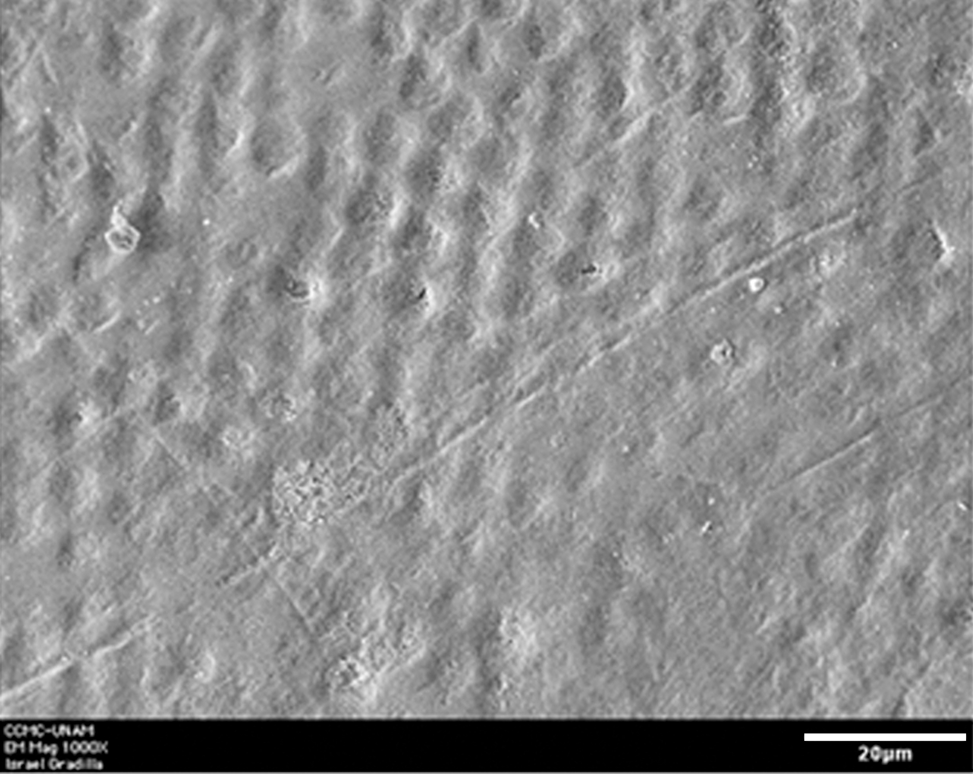
Representative SEM micrograph of samples from the control group showing occluded prisms and a smooth area (original magnification × 1000); scale bar = 20 μm.
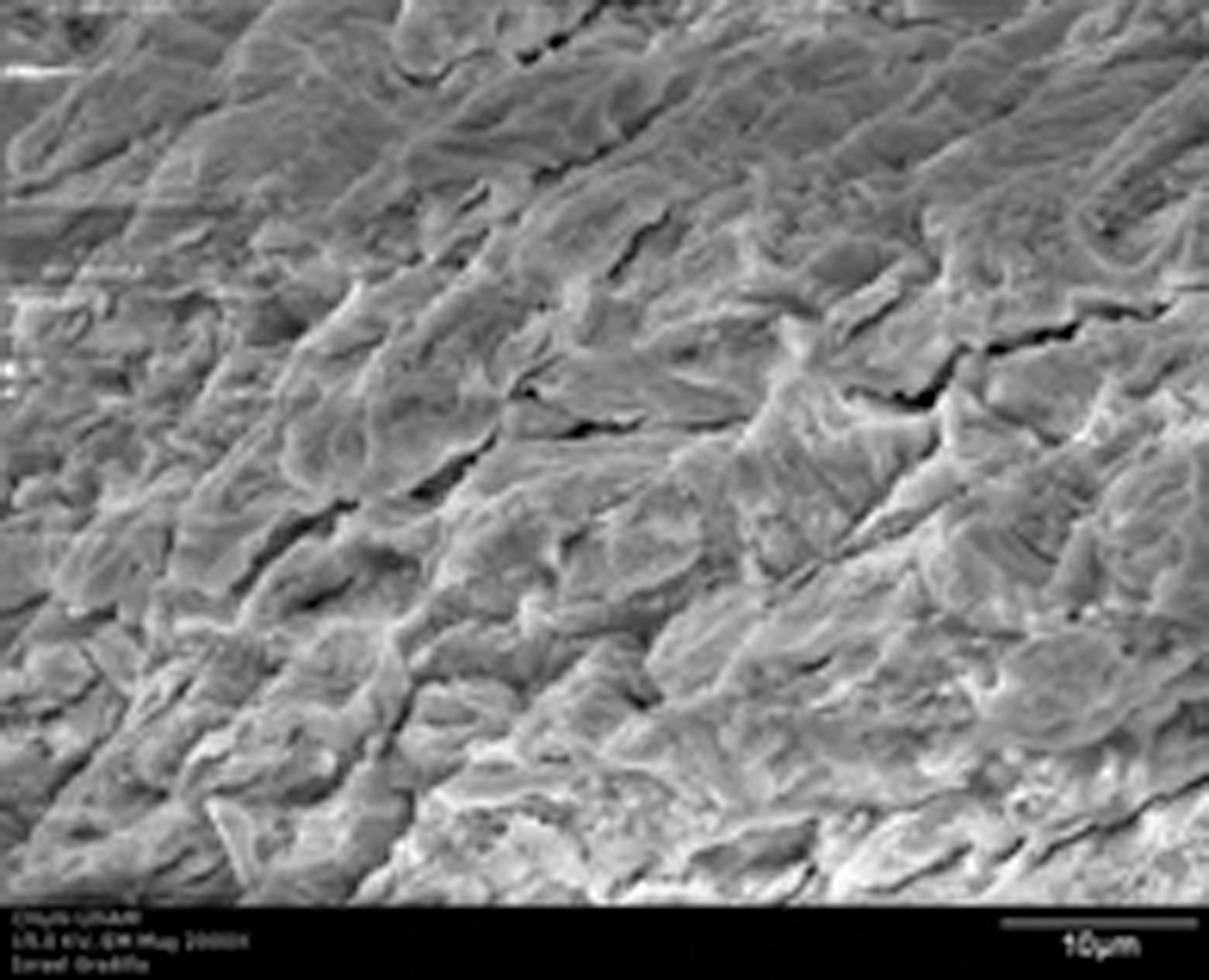
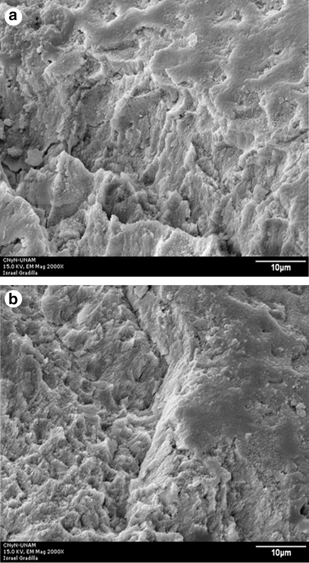
SEM micrograph of the enamel surface after Er:YAG laser irradiation at 100 mJ/10 Hz, 12.7 J/cm2 (original magnification × 2000); scale bar = 10 μm. A crack is evident crossing the central area of the surface.
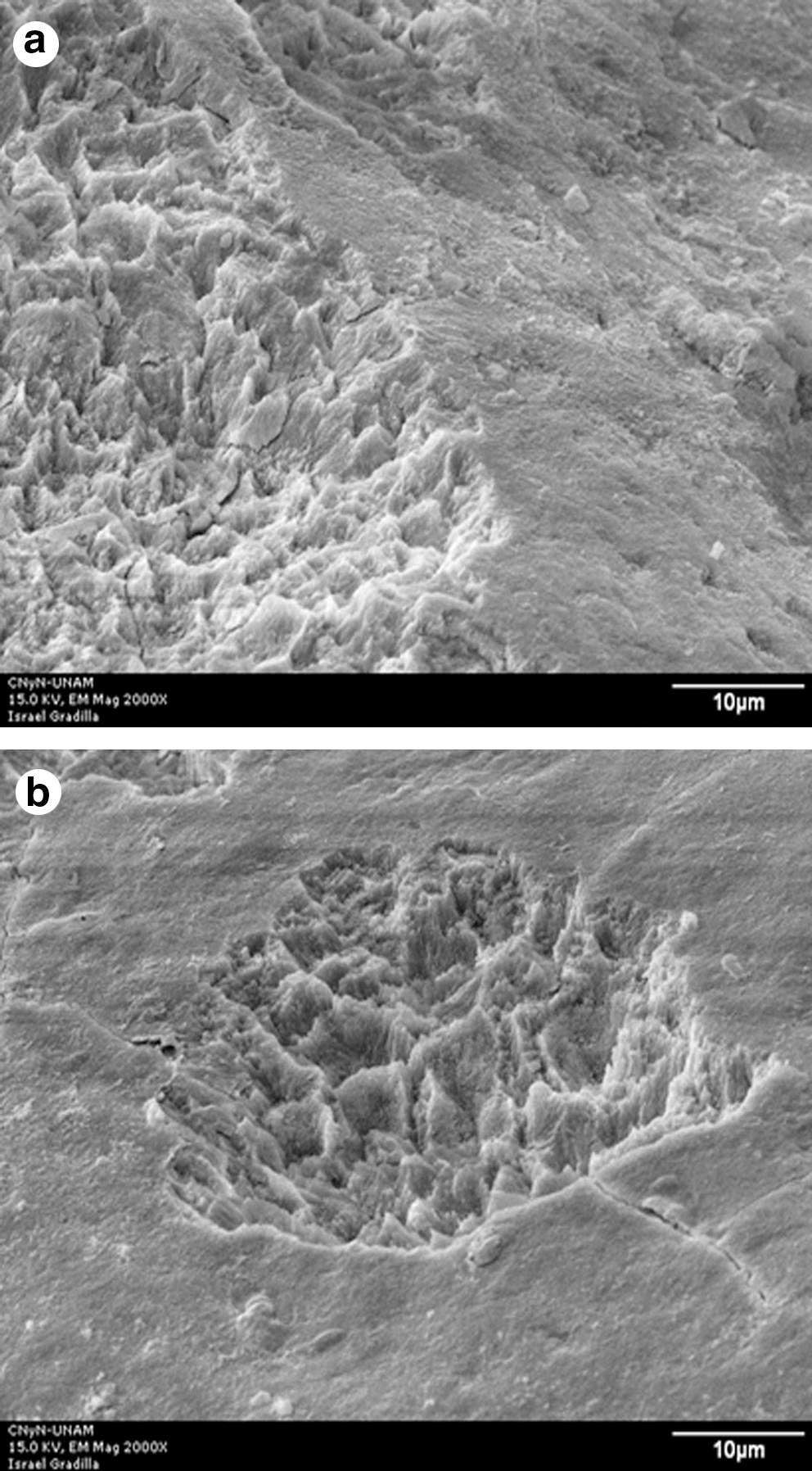
SEM micrograph of the enamel surface after Er:YAG laser irradiation at 100 mJ/10 Hz, 7.5 J/cm2 (original magnification × 2000); scale bar = 60 μm. (
(
Discussion
It has been reported 4 –14 that Er:YAG laser irradiation induces morphological changes in the enamel that include the formation of rough surfaces, cracks, and craters, which seem to be more prone to bacterial accumulation. Such morphological changes create favorable conditions for the development of carious lesions. 15 On the other hand, an increase in enamel acid resistance associated with Er:YAG laser irradiation of smooth surfaces has been suggested by several authors. 10,11,13 The results from a previous study 17 pointed out that the used subablative energy density did not promote an increase in the acid resistance of the occlusal enamel surface. In contrast, evident enamel morphological changes were found by SEM evaluation.
In order to further study the morphology and chemical characterization of these undesirable effects, the samples investigated in the actual study were irradiated under the same conditions used in a previous work, which were based on observations from pilot studies.
In this study, both SEM and AFM techniques, which are widely used in materials science, were chosen to evaluate the samples' morphology. Furthermore, SEM has been widely used in dentistry, whereas AFM has only recently been introduced to this discipline and is rarely applied to the study of enamel morphological changes produced by irradiation with any type of laser. Both techniques have advantages and disadvantages and they are complementary to each other. There are two main advantages of SEM versus AFM: first, one can observe samples almost without any sample preparation (other than the gold coating that is desired for high resolution images, which is not always needed) and second, one can obtain the chemical composition of a sample if the microscope is provided with an EDS detector. On the other hand, the main advantage of AFM is that one can not only obtain the surface morphology (as in SEM images) but also information in three dimensions, which makes it especially useful to measure heights of particles, valleys, and cracks.
For this reason, AFM was used to obtain 3D images of the crack produced in the enamel surface by Er:YAG laser irradiation. A detailed analysis of the cracks suggested that these defects show a triangular shape with a greater width than depth and with the base of the triangle oriented toward the irradiated surface, an apex in the bottom and a rough internal surface. These characteristics are more evident in the 3D image obtained from inside a crack in Group IV. Although the studied cracks had different widths and depths, it was not possible to establish a correlation between the employed irradiation conditions and the crack dimensions; consequently, additional studies are needed. The 3D image and cross–section analysis showed an evident stacking of material on the surface around the crack when the sample was not polished after laser irradiation, resulting in an apparently deeper and wider defect. This stacking phenomenon has not been reported in previous SEM studies, suggesting that AFM may be a useful tool to study more thoroughly the morphological characteristics of the enamel surface after Er:YAG laser irradiation. Considering that the average radius of Streptococcus mutans is 0.321 ± 0.007 μm, 24 the dimensions of the cracks and their internal rough surface shown in the 3D profile could be favorable sites for the accumulation of cariogenic bacteria such as S. mutans.
Regarding the SEM observations, non–irradiated samples (Group I) showed mainly exposed and closed prisms as well as smooth surfaces. Furthermore, all of the irradiated samples displayed rough areas, craters, and cracks, consistent with the results of previous studies. 4 –9
The use of SEM has provided relevant findings for the study of enamel morphological changes after laser irradiation. However, the addition of EDS as an analytical technique provides valuable information about the chemical changes on the irradiated enamel surface. Considering that the craters could be zones more susceptible to caries development because of their morphology (evident changes inside the crater and less pronounced in the outer area) it is important to determinate their chemical composition.
The EDS analysis revealed differences within the groups, depending upon the studied area, as well as among the groups, whereas it has been reported that laser treatment did not affect the mean percentage weights of Ca and P, or the Ca/P ratio on the enamel surface. 25 However, X–ray photoelectron spectroscopy (XPS) analysis reported that the binding energies of Ca 2p and P 2p of Er:YAG laser–irradiated bovine enamel were slightly different from those of control group. 22
Regarding the wt% of the studied elements, only O showed similar values among studied groups and areas. For Ca, there was no change in the wt% among groups and studied areas when higher energy density was used, suggesting that a lower energy density is a factor associated with the increase in Ca wt%, which could increase acid resistance to bacterial attack despite crater morphology. A tendency to P wt% stability was observed, but additional research is necessary to confirm it. Moreover, chemical changes, such as the reduction of phosphorus in the periphery area of the craters of Group IV, could increase the risk of development of carious lesions because of the important role played by phosphate ions in the demineralization–remineralization process of hydroxyapatite crystals.
Regarding Cl wt%, no significant difference between the crater and the periphery was observed when the highest energy density was used for Er:YAG laser irradiation, consistent with the findings of Ca and O, suggesting that this energy density only produces morphological changes on the enamel without structural variations. The differences found among groups and areas could be explained by atomic substitution in apatite, specifically chlorapatite (ClAp), as might be expected from the difference in electronegativities of the elements and the heat generated, which promotes atomic substitution, 26 specifically the temperature produced by lower energy densities of laser irradiation as used in Groups III and IV. Nevertheless, additional research is needed to confirm this hypothesis.
Conclusions
AFM observations revealed cracks characterized by a triangular shape with a greater width than depth and with their bases oriented toward the irradiated surface. Also, internal surfaces of the cracks were rough, and it was not possible to establish a clear tendency of the chemical changes observed inside and in the periphery of the craters. Finally, additional research is necessary to clarify the probable influence of the irradiation conditions on the morphology and chemical composition of the cracks and craters.
Footnotes
Acknowledgments
We thank Dr. Enrique Samano for his valuable support and Israel Gradilla for technical assistance, both from the Centro de Nanociencias y Nanotecnología, Universidad Nacional Autónoma de México (UNAM), and David Villanueva Jurado and Gerardo Guadarrama Álvarez, maxillofacial surgeons from the School of Dentistry, Universidad Autónoma del Estado de México (UAEM), for their assistance with obtaining the samples. This project was financed by UAEM and UNAM.
Author Disclosure Statement
No conflicting financial interests exist.