
Abstract
We present a laminar flow reactor for bone tissue engineering that was developed based on a computational fluid dynamics model. The bioreactor design permits a laminar flow field through its specific internal shape. An integrated bypass system that prevents pressure build-up through bypass openings for pressure release allows for a constant pressure environment during the changing of permeability values that are caused by cellular growth within a porous scaffold. A macroporous ceramic scaffold, composed of zirconium dioxide, was used as a test biomaterial that studies adipose stem cell behavior within a controlled three-dimensional (3D) flow and pressure environment. The topographic structure of the material provided a basis for stem cell proliferation and differentiation toward the osteogenic lineage. Dynamic culture conditions in the bioreactor supported cell viability during long-term culture and induced cell cluster formation and extra-cellular matrix deposition within the porous scaffold, though no complete closure of the pores with new-formed tissue was observed. We postulate that our system is suitable for studying fluid shear stress effects on stem cell proliferation and differentiation toward bone formation in tissue-engineered 3D constructs.
Introduction
Tissue engineering of bone substitutes uses bioreactors that support cell growth, cell metabolism, and cell differentiation. 1 Bioreactor cultivation can enhance cell proliferation and cell survival by improving mass transport of oxygen and nutrients during cell growth. 2 Furthermore, mechanical forces, such as shear stress, can induce the osteogenic differentiation of bone marrow stromal cells, adipose mesenchymal stem cells, or other multi-potent progenitor cells and can support extra-cellular matrix deposition.3–7 However, turbulence, bubbles, or eddies within bioreactor vessels can lead to detrimentally high mechanical forces that can cause cell membrane disruption and cell death.8–10 Therefore, a well-characterized fluid environment may facilitate a comparison of results from different culture systems and conditions. Computational fluid dynamics (CFD) modeling is a powerful tool that is used to better define the mechanical forces inside bioreactors.11,12
Apart from spinner flasks and rotating wall bioreactors, the main systems used for bone tissue engineering are perfusion reactors.4,13 Most of the systems for bone tissue engineering are custom-made devices that are developed for specific needs within research laboratories,4,14 whereas commercially available reactors mainly comprise systems for mammalian cell expansion. 13
The various perfusion bioreactors described in the literature differ not only with regard to their internal vessel shape but also in their perfusion mode. Bancroft et al. described a perfusion reactor with a cylindrical shape, where fluid flow is directed from top to bottom. 15 This system has been extensively studied in recent years with regard to osteogenic differentiation and extracellular matrix deposition of different flow perfusion schemes. 16 A similar principle was used by Jaasma et al., where an O-ring system supported scaffold fixation in order to prevent the lateral flow bypassing the scaffold. 17 In the reactor system developed by Cartmell et al., cylindrical scaffolds were transversely perfused through the rounded surface at various perfusion rates. 18 Perfusion in the vertical direction, through culture chambers, which were connected by an U-shaped tube, characterized a reactor system developed by Wendt et al., where an oscillating perfusion mode supported cell-seeding efficiency in three-dimensional (3D) scaffolds. 19 Grayson et al. described a reactor system suitable for in situ visualization where six cylindrical scaffolds were arranged in a star-like fashion and perfused from a central inlet through distributing channels from bottom to top. 20 A fixed-bed perfusion chamber, developed by the group of Pörtner for cartilage engineering, allowed transverse perfusion from above the cylindrical scaffolds, situated in small cavities, with a counter-current flow of gas on top of the medium. 21 Another interesting approach has been described by Li et al., where a customized porous scaffold, with an inner blind-ending tunnel, was perfused through the central tunnel toward the pores while being surrounded by a culture medium in a reservoir. 22 A perfusion system by Zhao et al., modified by Kim and Ma, allows parallel (horizontal) or transverse flow through three scaffolds placed in a row.5,23
This large variety of perfusion bioreactors has not only been an evolution of trial and error for bone tissue engineering, but also underscores the point that the optimal way for ex vivo tissue growth has not yet been found. For example, the experimental data from the different approaches are not always in favor of dynamic cultures, and some investigators have observed either a lack of extra-cellular matrix formation or cell proliferation and even cell death. 24 In order to compare the effects and ranges of shear forces acting on cells in these different studies, one has many considerations, including the cell type and source, the culture medium perfusion mode and rate, the reactor shape, and the scaffold perfusion characteristics and material properties.
To estimate the shear stresses acting on cells, CFD models have been applied to some of the systems just described.23,25–28 Most of these models have focused on describing the flow through porous scaffolds using various approaches, without taking the shape of the reactor itself into account.23,27,29–34 Considering the bioreactor shape in the modeling approach, a recent study suggested a quadrangular design being superior to the frequently used cylindrical design for improved scaffold perfusion. 35
We have recently developed a differential pressure laminar flow reactor based on a CFD model that supports constant pressure equilibrium within a laminar flow environment.36,37 The flow pattern is based on the specific shape of the reactor vessel. The bioreactor differs from current models based on its internal bypass system that provides a constant pressure environment by the use of irises, which were implemented in the culture vessel between the upstream and downstream sides of the scaffold. During cell proliferation, within a porous scaffold, a decrease in scaffold permeability is anticipated, which will eventually lead to a pressure build-up upstream from the scaffold. By sensing changes in the differential pressure upstream and downstream from the scaffold, the iris system will gradually open to release any pressure build-up in the upper chamber and prevent high shear stresses that would otherwise potentially damage the growing cells.
In the present study, we aimed at examining the biological performance of this laminar flow bioreactor with regard to the growing bone substitutes in a defined pressure environment. We used an inert macroporous ceramic matrix, seeded with human adipose mesenchymal stem cells, and tested for cellular growth and osteogenic differentiation during continuous perfusion culture.
Materials and Methods
Bioreactor design
The differential pressure laminar flow reactor design was based on a CFD model using FLUENT 5.5 software36,37 from which a customized prototype was built (Zerspannung Metallbau). Figure 1a shows the bioreactor prototype, and Figure 1b demonstrates a schematic view of the setup. Figure 2 shows a cross-sectional view of the reactor interior with results of CFD simulation for a closed and open bypass system.

Bioreactor prototype

The computational fluid dynamics model (FLUENT 5.5) as a cross-sectional view of the bioreactor with the bypass system and the scaffold calculated for a scaffold permeability of 5×10⁻⁹ m2. Velocity vectors colored by velocity magnitude (m/s; e-05=10−5) with the irises are closed
Differential pressure above and below the scaffold holder was measured by piezo-resistive pressure sensors (GMSD 25 MR, Greisinger electronic GmbH) and was continuously monitored via an external control box (Mitsubshi). Regulation of the iris bypass system was done either manually or automatically through the control box via a motor-driven hinge. For temperature control, the bioreactor was placed in an incubator (Sanyo) at 37°C. Cell culture media (DMEM-F12 with supplements, see next) were perfused at a rate of 1 mL/min by a roller pump (Ismatec). A custom-made bioreactor scaffold holder allowed the simultaneous cultivation of seven cylindrical scaffolds, each with a diameter of 10 mm and a height of 3 mm. If premature removal of any of the scaffolds was required during the experimental course, the scaffold holder openings could be closed individually with plastic inserts.
Flow and pressure characterization
Laminar flow
Laminar flow describes the fluid moving in parallel layers without disruption between the layers. The dimensionless Reynolds number can be used to characterize the flow conditions of laminar flow with a critical value <2000 versus a turbulent flow >3000. 38
The Reynolds number can be calculated as
where V is the average flow velocity (m/s), d is the hydraulic diameter of the bioreactor (m), ν is the kinematic viscosity of water (m2/s) (with ν=10−6 m2/s=1 cSt at 20°C), Q is the volumetric flow rate (m3/s), and A is the cross-sectional flow area (m2).
From the CFD calculation, we obtained a Reynolds number in the bioreactor of 2942 under conditions with the irises closed and a Reynolds number of 641 with the irises open.
Pressure drop
The pressure gradient (Δp/Δx) through the zirconium dioxide scaffold (below) can be calculated using Darcy's Law:
where V is the average flow velocity (m/s1), μ is the dynamic viscosity (Pa·s) of water as equivalent to medium (with μ=0.6915 cP [centipoise]=0.6915 mPa·s=6.915×10⁻⁴ Pa·s at 37°C), and κ is the permeability (m2) (with κ=5×10⁻⁹ m2).
The average flow velocity V can be derived from
where Q is the volumetric flow rate in m3/s, and A is the total scaffold area in m2.
Therefore,
For a scaffold thickness of 3 mm=3×10⁻³ m, we get a pressure drop in the range of
Average shear stress inside pores
To calculate the shear stress inside the pores, the modified Brinkman equation for porous media can be applied:
39
where τ is the average shear stress on the cell surface (dyn/cm2 or Pa), B is the Brinkman constant for flow around cylinders or spheres (B=4/π for cylinders, and 3/π for spheres), and μ is the viscosity of the medium (μ=1.2 cP) at 37°C.
For our model, an average shear stress is calculated in the range of τ=4.67×10⁻⁴ Pa.
Scaffolds
Macroporous ceramic scaffolds, made from doped zirconium dioxide in the shape of cylindrical discs with a diameter of 10 mm and a thickness of 3 mm, were used (Sponceram; Zellwerk GmbH). Mean pore size was 400–600 μm with a high interconnectivity and an intrinsic permeability κ of 2.31×10⁻⁸ to 6.25×10⁻¹⁰ m2. 31 For a comparison, bovine cancellous bone has been reported to have a permeability between 2.33×10⁻¹⁰ and 4.65×10⁻¹⁰ m2. 40
Cells
Primary human adipose mesenchymal stem cells were obtained from donors undergoing abdominoplasty. Informed consent was obtained from all donors, and the process was approved by the ethics committee of the Hannover Medical School. Fat tissue was dissected and digested by collagenase (Typ CLS, CI-22, Biochrom), and stromal cell fraction was obtained by sequential centrifugation using standard protocol.41,42 Cells were plated in T150 culture flasks and expanded in DMEM-F12 medium (PAA Laboratories) supplemented with 5% fetal calf serum (Biochrom), nonessential amino acids (Biochrom), sodium pyruvate (Biochrom), and penicillin-streptomycin (PAA Laboratories) at 37°C with 5% CO2. Multi-potency of the isolated stem cells was routinely verified by differentiation into the adipogenic, chondrogenic, and osteogenic lineage and demonstration of common stem cell surface markers by fluorescence-activated cell sorting analysis (data not shown).42,43 Cells were trypsinized for passaging and scaffold seeding.
Culture conditions
For scaffold seeding, cells from passage 2–4 were used. Cells were suspended in 100 μL culture medium and seeded at densities of 5×10⁵ cells per scaffold on both sides in a small petri dish. A period of static cultivation for 24–48 h was allowed for cell attachment before the start of experiments. A cell seeding efficiency (X) of about 40% was achieved as calculated by
A total of 15 experiments were included in the analysis. Each experimental course consisted of a static and a dynamic culture group, each with seven cell-seeded scaffolds that were cultured under defined culture conditions: (1) Static cultures were maintained in an incubator at 37°C with 5% CO2 with DMEM-F12-Medium and supplements as just stated. (2) For dynamic cultivation, scaffolds were transferred to the bioreactor, where cultivation was performed at 37°C without the addition of CO2, in a standard cell culture medium, which was additionally supplemented with HEPES buffer solution at 0.01 M (PAA Laboratories) in order to maintain stable pH. The culture period spanned from several days up to 2 months. For dynamic cultivation in the bioreactor, perfusion rate was set at 1 mL/min in the top to bottom direction. Pressure, temperature, and pH were continuously controlled at regular intervals.
Analysis
Cell proliferation
Cell proliferation was assessed by CellTiter-Blue® cell viability assay according to the manufacturer's instructions (Promega). Scaffolds were transferred to 24-well plates in 1000 μL of culture media, and 200 μL of cell-titer-blue reagent solution was added. After gentle mixing and 2 h of incubation at 37°C with 5% CO2 in an incubator, the supernatant was transferred into black 96-well plates and analyzed by spectroscopy at 560 nm emission and 590 nm extinction (GENios, Tecan). Averages from three to five experimental courses were taken; static and dynamic culture results were statistically compared by t-tests (p<0.05) (Excel; Microsoft).
Grinding section
Scaffolds were fixed in formaldehyde and embedded in methyl methacrylate and glycol methacrylate (Technovit). Specimens were cut, ground, then stained with toluidine blue, and analyzed by microscopy (Olympus).
Cell viability
Cell-seeded scaffolds were stained by fluorescein diacetate 2.4 μM 44 and analyzed via microscopy (Olympus SZX16 research stereo microscope).
Cell differentiation stains
Scaffolds were fixed in formaldehyde. von Kossa staining was performed with 2.5% silver nitrate (Merck) and developed with carbonate formaldehyde (Sigma). Alzarin Red S staining was performed with a 10% solution at pH 4 for 30 min (Sigma) and washed with borate buffer.
Polymerase chain reaction
RNA isolation was performed with Trizol reagent according to the manufacturer's protocol (Gibco) and treated with DNASE I (Invitrogen). complementary deoxyribonucleic acid (cDNA) was processed with a reverse transcriptase using an iScript™ cDNA Synthesis kit (iCycler; BioRad). Polymerase chain reaction (PCR) reaction was performed with TaKaRa ExTaq kit (TaKaRa) as follows: Primary denaturation and enzyme activation at 98°C for 1 min, then 40 cycles with denaturation at 98°C for 10 s, annealing temperature (see Supplementary Table S1) for 30 s, extension at 72°C for 1 min, and, finally, extension at 72°C for 5 min (iCycler; BioRad). Primer and reaction details are presented in Supplementary Table S1.
Electron microscopy
Scaffolds were fixed in Sodium-Cacodylate buffer (Merck) containing 10% glutaraldehyde (Polysciences), dehydrated by ascending acetone dilutions, and subjected to critical-point drying with a CPD030 (Bal-Tec) before gold sputtering with a surface electron microscopy (SEM) Coating System (Polaron). Specimens were viewed in an SEM500 (Philips) under vacuum at 10 kV and analyzed by software developed by Gebert & Preiss. 45
Results
Fluid flow simulation
In order to characterize fluid flow in the bioreactor system, CFD simulation was performed for a scaffold permeability κ=5×10⁻⁹ m2, which was in the range of the experimental permeability values of zirconium dioxide scaffolds (2.31×10⁻⁸±6.25×10⁻¹⁰ m2). 31 Typical results from CFD modeling are shown in Figure 2, where opening in the iris system resulted in a reduction of flow velocity (Fig. 2a, b) and pressure distribution (Fig. 2c, d) across the scaffold.
Bioreactor iris system
Opening the iris system resulted in a decrease of the differential pressure across the scaffold without being affected by changes in the pump flow rate, whereas the differential pressure increased when the scaffold holder was blocked.
For designing the prototype bioreactor, results from the theoretical model needed to be transferred into a mechanical design that included a suitable pressure sensor. Experimental results demonstrated a baseline differential pressure of −4 mbar between the upper and the lower pressure sensor (ΔP=Pupper − Plower) for the filled bioreactor vessel with unseeded Sponceram scaffolds. The opening of the iris system resulted in a further decrease of differential pressure across the scaffolds (Fig. 3). The measured differential pressure values did not change for different pump rates in the range between 0.2 and 10 mL/min (Fig. 3). When the scaffold holder was totally blocked, differential pressure increased, resulting in activation of an automatic opening mechanism for the iris system. For a completely blocked scaffold holder, a differential pressure of −1.6 to −2 mbar was measured for a full iris opening of 100% (Fig. 3, brown line).

Differential pressure measured in the bioreactor prototype with zirconium dioxide scaffolds at various pump perfusion rates depending on iris aperture (in %). Baseline differential pressure for closed irises was at −4 mbar for pump rates between 0.2 and 10 mL/min (orange line), and gradual opening of the irises decreased differential pressure to −8 mbar (violet line). Simulating tissue growth inside scaffold pores by replacing zirconium dioxide scaffold with impermeable plastic inserts resulted in a steep rise of differential pressure in the positive range already at 0.2 mL/min pump rate, and this pressure build-up forced plastic inserts out of the scaffold holder. Full opening of irises released differential pressure to −1.5 to −2 mL/min when the scaffold holder was blocked by plastic inserts.
Long-term dynamic culture
Long-term dynamic culture was not accompanied by significant changes of differential pressure across the macroporous scaffold.
No relevant changes in differential pressure across the macroporous scaffold were observed during long-term culture, for approximately 2 months of cell-seeded Sponceram scaffolds in the bioreactor. Based on our calculations, a decrease in scaffold permeability from κ=5×10⁻⁹ m2 to κ=1×10⁻¹³ m2 due to cell growth would have been required to activate the opening mechanism of the iris system.
Cell proliferation
Cell proliferation was not increased under dynamic culture compared with static culture.
During the first 6 days of culture, cell viability testing showed a three-fold increase in fluorescence intensity corresponding to cell proliferation in static and dynamic cultures (Fig. 4). No difference in cell proliferation was seen between static and dynamic culture conditions. These results indicate that the 3D scaffold provided a suitable environment for the proliferation of mesenchymal stem cells, which was not further affected by shear stresses.
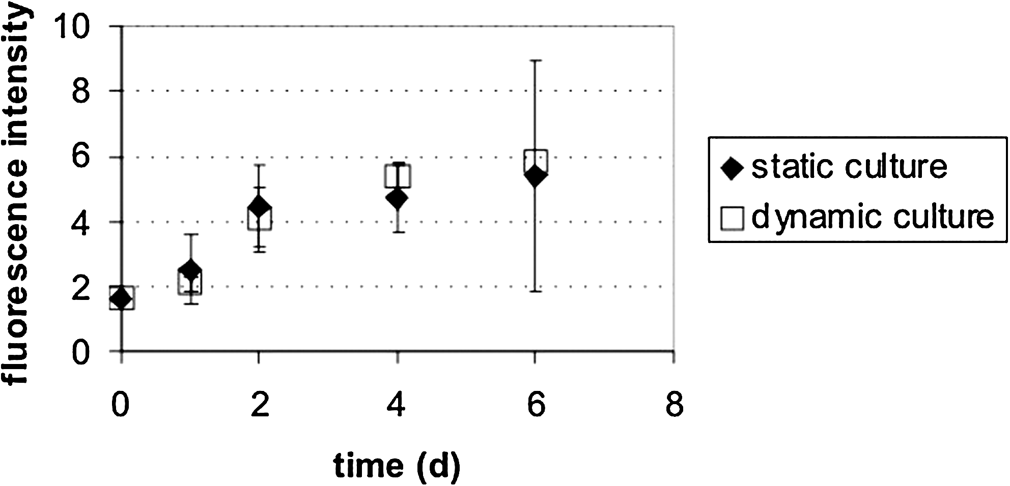
Cell proliferation as measured by fluorescence intensity (560 nm/590 nm) showed similar growth curves with no significant differences between statically and dynamically cultured mesenchymal stem cells grown on macroporous ceramic scaffolds, during the first week of culture.
Cell viability and cell cluster formation
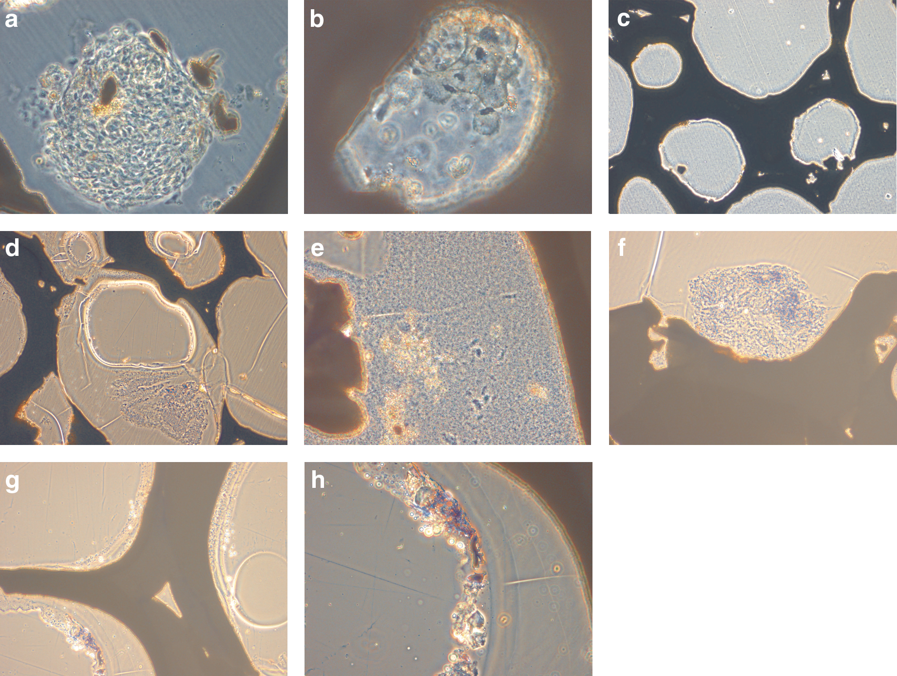
Dynamic culture preserved cell viability and led to cell cluster formation inside the porous scaffold.
Fluorescence staining, for cell viability, showed a dense homogenous distribution of stem cells within the macroporous ceramic scaffold under static and dynamic culture conditions after 1 week (Fig. 5a, b). Static culture cells were observed as smoothly lining the pore walls (Fig. 5c) under dynamic culture conditions in the bioreactor; cluster formation of cells inside the pores was observed as early as 3 days of dynamic culture; cluster formation at 1 week is shown in Figure 5d. High cell viability was preserved at 1 month of culture under static (Fig. 5e) and dynamic (Fig. 5f) culture conditions.

Stem cells growing on macroporous ceramic scaffold demonstrated high viability and homogenous distribution under static
Effects on scaffold pores
Long-term dynamic culture results in the partial filling of scaffold pores with cells and extracellular matrix deposits.
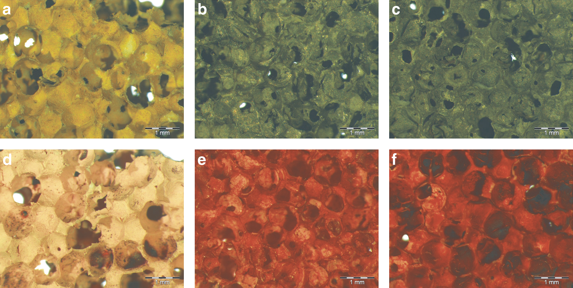
In order to determine whether dynamic culture conditions would support cell proliferation and differentiation inside the macroporous scaffold pores, ground sections were obtained (Fig. 6). Similar cell cluster formations, as observed with the fluorescence viability staining, were observed at 3 weeks of dynamic culture (Fig. 6a, b). Figure 6c demonstrates a cross-sectional view of an empty control scaffold without the cells, whereas the dynamic culture, at 8 weeks, showed partially filled scaffold pores (Fig. 6d). The content of scaffold pores consisted of an amorphous matrix (Fig. 6e), a cluster-like matrix formation (Fig. 6f), or pore walls lined with deposits of metachromatic particles (Fig. 6g, h), which demonstrated mineralization at 8 weeks of dynamic culture.
Ground sections of zirconium dioxide ceramic scaffolds showed cell clusters inside larger
Osteogenic differentiation
The cultivation of adipose mesenchymal stem cells on ceramic macroporous scaffolds induced osteogenic differentiation without differentiation supplements in the culture media in static and dynamic cultures.
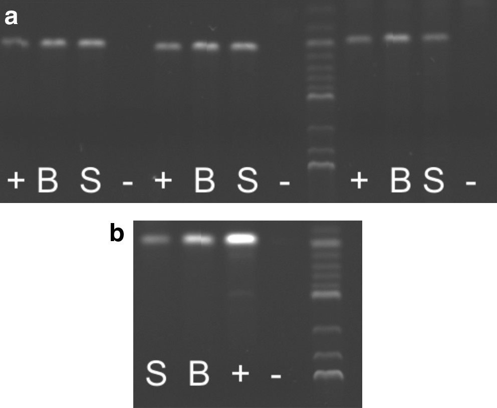
The influence of static and dynamic culture conditions on the osteogenic differentiation of mesenchymal stem cells on macroporous ceramic scaffolds was evaluated by specific histological staining and gene expression analysis by a polymerase chain reaction. Staining by the von Kossa technique for mineralization and Alzarin Red for calcium deposition showed a positive staining compared with plain control samples without cells, but there were no differences between static and dynamic culture conditions at 1 month (Fig. 7a–f). PCR for early (collagen type I, bone alkaline phosphatase, and osteopontin) and late (osteocalcin) osteogenic markers demonstrated positive gene expression that was similar to bone control samples at 1 month, without significant differences between static and dynamic cultures (Fig. 8a, b).
Osteogenic differentiation of adMSCs cultured on Sponceram scaffolds, without differentiation media supplements, under static and dynamic culture conditions:
Gene expression analysis of early
Extra-cellular matrix formation of mesenchymal stem cells
Extra-cellular matrix formation of mesenchymal stem cells on macroporous ceramic scaffolds differed profoundly between static and dynamic cultures.
Extra-cellular matrix formation was further examined by raster electron microscopy. There was a marked difference in extracellular matrix formation between the scaffolds cultivated under static conditions (Fig. 9a, c) compared with those cultivated dynamically in the bioreactor (Fig. 9b, d): Stem cells in static culture showed plain spreading with only sparse extra-cellular matrix formation (Fig. 9a, c). In contrast, in scaffolds cultured under continuous perfusion in the bioreactor, conglomerates of extra-cellular matrix were found inside the pores (Fig. 9b, d). Stem cells in dynamic culture produced crystalline-like deposits (Fig. 9e, g). Figure 9f and h show a higher magnification of the mineralized matrix formed inside scaffold pores, under perfusion culture conditions.

Static culture of mesenchymal stem cells on Sponceram ceramic showed plain cell spreading with only sparse extra-cellular matrix formation (filled arrows)
Discussion
Bioreactor design that promotes a controlled extra-cellular environment in order to support tissue growth can be a challenge. For bone tissue engineering, several approaches such as rotational reactors, perfusion reactors, or stretch and pressure chambers have been used to imitate the physiologic environment for bone formation and repair.6,14,15,19,46–48 Besides the successful cultivation of bone substitutes in various other reactor types, perfusion culture is still the most common concept used for bone tissue engineering. 4 Several other bioreactor models have been already characterized by CFD modeling of internal flow and pressure distribution.11,26,28,34,49–51 In our model, CFD simulation helped define the optimal design for laminar flow perfusion with concomitant pressure regulation via an internal iris system. To our knowledge, this approach is unique compared with existing perfusion bioreactor models.
The benefit of an integrated pressure release system for the cell culturing of a 3D construct, within a flow field, warrants further evaluation. In order to activate the pressure release system in our reactor, a decrease in scaffold permeability, toward values of κ=1×10⁻¹³ m2, would have been required. For comparison, reported permeability values of acellular or cellular collagen gels are in the range of 10−11 to 10−15 m2. 50 The cellular growth and deposited extra-cellular matrix within the pores of the chosen macroporous ceramic scaffold, which had an intrinsic permeability in the range of κ=5×10⁻⁹ m2, was, therefore, not sufficient to induce a relevant change in permeability for activation of the iris system. The scaffold used in our studies can be manufactured with a different porosity. The surface properties of the scaffold can be further improved by polymers, bioactive ligands, or hydroxyapatite coating in order to enhance cell attachment or cell differentiation. For the present study, we decided on the plain doped circonium dioxide material, as it has the advantage of being inert and of not degrading or releasing particles in the culture medium during long-term culture. The bioreactor presented here was practical to use and can be used to test and optimize different scaffolds, cells, and conditions.
Another consideration is the size of the irises, as a fine balance is required to regulate pressure release and scaffold perfusion. Increasing the size of the bypass system will diminish the flow through the scaffold, thereby reducing the benefit of perfusion with regard to mass transport and oxygen delivery to the cells. Further CFD studies will use 3D simulation of the bioreactor interior to examine the effects of iris size, scaffold shape, and thickness and scaffold permeability on the flow and pressure field.
Since our CFD model considered the full shape of the bioreactor, it did not picture the precise internal structure of the scaffold itself. Therefore, shear forces inside the interconnected tortuous, porous system of the scaffold can only be estimated and might be in a wider range than calculated. Furthermore, any reduction in pore diameter will result in a further increase in shear stresses inside, affecting cell physiology. Some studies have used micro computertomography-based CFD simulations of flow through a scaffold in order to better define the shear stresses inside.25,27,29 However, this focus does not define the overall flow field of the reactor itself, in that a drop in the perfusion of the scaffold occurs with less perfusion at the edges than through the center. 49 We did not observe marked differences between the center and the edges of the scaffold that were cultured in the bioreactor, compared with the static culture in the present study. Instead, we worked with a small diameter of 11 mm scaffolds compared with clinical-size scaffolds. These differences might be not as pronounced with increasing the scaffold sizes. The bioreactor prototype would allow the cultivation of larger scaffolds similar to other designs. 49 Our first CFD simulations used a scaffold thickness of 1 mm. For any increase in scaffold thickness, in order to achieve a clinically relevant construct, further changes in the interior design of the bioreactor, such as adjustment of the sizes of the irises, are to be expected in order to optimize the flow field through the scaffold.
The results of the present study suggest that the 3D structure and material properties of the scaffold itself greatly influence stem cell behavior and physiology. Interestingly, without the addition of media supplements that induce osteogenic differentiation, the stiff matrix itself endorsed cell differentiation toward an osteoblastic phenotype, which is consistent with other observations.52–56 The marked difference in extra-cellular matrix deposition, observed between static and dynamic culture conditions, reflects the additional effects of shear stresses on stem cell differentiation.
The use of adipose-derived mesenchymal stem cells, as in the present study, is a common tool for tissue engineering applications. Adipose-derived mesenchymal stem cells are characterized by their plastic adherence, multipotency (differentiation into osteogenic, chondrogenic, and adipogenic lineage), and expression of specific surface markers (positive for CD 105, CD 73, and CD 90; negative for CD 45, CD 34, and HLA-DR) as defined by the International Society of Cellular Therapy. 43 Besides, adipose-derived mesenchymal stem cells have a similar potential for osteogenic differentiation compared with bone marrow stormal cells and can be easily derived in high quantities with a low morbidity. 42
The finding that cell proliferation was not further stimulated by perfusion culture, compared with static culture, might have several reasons: First, the shear stresses of the fluid environment might adversely affect cell attachment and cell division; and second, the stiff matrix itself might induce early cell differentiation and, hence, inhibit further proliferation. A more elastic matrix material might react differently with regard to cell proliferation. Cell cluster formation inside the pores, as it was found in dynamic but not in static culture, might also support cell differentiation and extracellular matrix deposition and might be an equivalent to bone nodule formation, described in osteoblastic two-dimensional cultures.57,58 Since cell clusters were found at early and late culture stages during dynamic culture and stained by fluorescein diacetate throughout the experimental course, for which an intact cell membrane is required, we do not anticipate apoptosis or cell death as a reason for cluster formation. However, it would be interesting to test whether a different biomaterial with improved cell adhesion properties or an altered flow regime in the bioreactor might prevent cell cluster formation.
Further research is necessary in order to connect these findings regarding bioreactor studies toward in vivo bone formation. Some data already suggest the effects of interstitial flow in Haversian canals on bone formation and bone remodeling.59–61 Furthermore, mineralization processes of stem cells or osteoprogenitor cells generally start with vascular ingrowth into the callus and vascular perfusion. New approaches in bone tissue engineering include co-culture systems such as mesenchymal stem cells or osteoprogenitor cells with endothelial cells or osteoclasts in static and dynamic 3D culture systems.50,62–65
In summary, we have introduced a novel laminar flow differential pressure bioreactor system suitable for the induction of mesenchymal stem cell differentiation toward an osteogenic phenotype and the cultivation of tissue-engineered bone substitutes. An integrated bypass system in the form of irises allows flow control through the scaffold and pressure release toward the sides that can occur with decreasing permeability and increasing resistance during cellular growth and matrix deposition. Experimental results are consistent with previous reports on the cultivation of tissue-engineered bone substitutes in perfusion bioreactors.6,16,17,20,23,52 The problem relating to low yields of new tissue formation in a bioreactor may also be related to using a stiff matrix that can induce the early differentiation of stem cells, and the mono-cellular culture system which is not mimicked by nature in the same way. We propose that our system is suitable for studies of mechanical forces on cell proliferation and differentiation in a defined flow and pressure environment. Further work needs to address the variable shear stresses within the 3D matrix by defined matrix structures and sizes as well as modeling continuous cell growth within the matrix during bioreactor cultivation.
Footnotes
Acknowledgments
The authors wish to thank A. Lazarides (MHH) for technical support, G. Preiss (MHH) for help with REM analysis, and J. Zwicker (Zerspanung Metallbau, Hannover, Germany) and K. Gadischke (IGEA, Anlagenbau, Bückeburg, Germany) for their contribution to prototype development. This work has been supported by a start-up grant from Hannover Medical School (HILF) for Birgit Weyand, MD.
Author Disclosure Statement
No competing financial interests exist.
References
Supplementary Material
Please find the following supplemental material available below.
For Open Access articles published under a Creative Commons License, all supplemental material carries the same license as the article it is associated with.
For non-Open Access articles published, all supplemental material carries a non-exclusive license, and permission requests for re-use of supplemental material or any part of supplemental material shall be sent directly to the copyright owner as specified in the copyright notice associated with the article.