
Abstract
The purpose of this study was to provide a simplified alternative technology and format for direct current stimulation of mammalian cells. An incubatable reusable stimulator was developed that effectively delivers a regulated current and does not require constant monitoring.
Introduction
Determining the effects of electric fields (EFs) on cells has been an area of interest for many years.1–7 EFs have been shown to be a signaling cue for cell migration,1,8 mediate growth cone steering, 9 induce cellular alignment,10,11 influence anatomical development, 12 and aid in wound healing and regeneration. 13 Stimulation setups for these types of studies can vary, depending on the application. McCaig et al. 14 and Robinson 15 describe an experimental setup and a protocol for stimulating cells in vitro. The setup was effective for cells not requiring incubation, but for mammalian cells, modifications may be needed. For example, Cork et al. 16 designed and fabricated a field chamber and a stimulator to expose PC12 cells (rat clonal pheochromocytoma cell line) to field strengths from 5 to 100 mV/mm. Each field chamber could house two cell cultures and was placed inside a 37°C, 7% CO2 incubator. However, the chambers were connected to the stimulator by a segment of flat eight-stranded ribbon cable that fed over the closed incubator door to the stimulator set up on the outside. The system also included digital current and voltage meters and a channel selection switch. In addition to the space required for a multicomponent system of this type and specialty chamber, a dedicated incubator may also be necessary.
Borgens et al. 10 designed and fabricated a special chamber and an incubator system to electrically stimulate rat astrocytes. The system was a bench-top setup on a microscope stage and included several components. A 37°C incubator was created around the microscope by fitting it with plexiglas and utilizing a thermostatically controlled heater. An indwelling microthermoprobe was used to constantly monitor the temperature, and an in-series multimeter was added to monitor the current. Pan and Borgens17,18 utilized a heated (35°C) microscope stage setup to apply EFs to chick peripheral neurons for 3–6-h periods. This arrangement was favorable to the cell type examined and stimulation duration chosen and allowed for real-time recording and photography of the cultures. However, for nonreal-time applications and long stimulation periods (≥10 h), a modified arrangement may be more suitable for some cell types. In preliminary work, we found that for extended stimulations, mammalian central nervous system (CNS) neurons had better survival rates and viability when incubated in a traditional CO2 incubator versus a microscope stage-based setup.
As an alternative, a self-contained, incubatable direct current stimulator was developed here that effectively delivers an EF to cells. The circuit arrangement allows the stimulator to be housed inside a traditional CO2 incubator during experimental runs without compromising its output current regulation. This provides a more favorable environment for some cells types and allows longer-duration experiments without concerns for gas regulation. In addition, it eliminates the need for customized or dedicated incubators and multidevice setups. Since it is reusable, fabrication of a new device or replacement of circuit components for each experiment is not required. It can also be used with commercially available, stimulation-compatible cell culture chambers.
Materials and Methods
Stimulator fabrication
The stimulator circuit is based on the National Semiconductor Corporation's zero-temperature coefficient configuration
19
using the LM334Z three-terminal adjustable current source. A schematic is shown in Figure 1. Current stability at temperatures greater than ambient is achieved with this circuit, since it compensates for increases in current due to temperature rises. The output current, ISET, is established by adjusting the variable resistors R1 and R2 to values resulting from Equations (1) and (2). It can be set to any value between 1 μA and 10 mA.

Schematic diagram of stimulator circuit. Variable resistors (potentiometers) R1 and R2 set the circuit current in accordance with Eqs. (1) and (2), while RSeries is used to monitor it. RLoad represents total load resistance (i.e., stimulation chamber, bridges, and medium), which connects to the stimulator through spring connectors and platinum electrodes.
Fixed resistors of suitable values could also be utilized. Since the LM334Z's operating voltage limit is 40 V, four rechargeable 250-mAh, 9-V nickel-metal-hydride batteries were placed in series giving a total power capacity of 36 V. All circuit components (e.g., LM334Z, resistors, diode, and batteries) have operating temperature ranges well above and below 37°C, and thus the incubator environment does not place undue stress on them and shorten their life. This enhances the stimulator's longevity and reusability.
Xenopus cell culture
To determine if the stimulator could adequately supply an EF to and invoke responses from cells, experiments were conducted on cell types known to respond to applied EFs, Xenopus laevis neurons and myoblasts. For these experiments, cell culture/stimulation chambers were fabricated as described by McCaig et al. 14 using No. 1 coverglass strips. Embryos were developed and dissected, and cells harvested and cultured in accordance with protocols outlined by Tabti et al. 20 Cells were harvested from stage 19 to 21 embryos and plated for 11 h before application of the field.
Incubatable setup for mammalian cell culture
For cell culture and application of the EF to mammalian cells, Ibidi μ-Slide I IbiTreat chambers (Ibidi; #80106) were purchased. It has internal dimensions of 50 mm×5 mm×0.4 mm, contains medium reservoirs on both ends, and since cells can be fixed and stained within the chamber, facilitates microscopy. Each reservoir can hold over 1.5 mL of the medium. These features make it suitable for electrical stimulation applications. The setup consists of 1% agarose-filled bridges (mixed with medium), the cell culture/stimulation chamber, 100-mm medium-filled petri dishes (to house bridges), platinum electrodes (0.5-mm diameter; 7-cm long), and a stimulator (Fig. 2). The platinum electrodes were soldered to attachment wires to extend their length. Bridges were made of a flexible silicone rubber tubing (Barnant; #62998-490) with dimensions 3/16″I.D., 1/4″O.D., and cut to an appropriate length for the setup and stimulation duration. 15 They were placed in petri dishes so that their tips were submerged ∼4 mm or less. The opposite ends of the bridges were placed inside the chamber reservoirs to make electrical contact with the circuit. Reservoir caps were first removed and replaced with parafilm to help secure the bridges in place. A hole was punctured in the parafilm to allow bridge entry. The entire stimulation setup is placed on an aluminum-foil-covered tray (of any size and type) and placed on the shelf of a 37°C, 5% CO2 incubator. Before placing the cells and stimulator on the tray, items were UV sterilized. The stimulator was disinfected with 70% ethanol. The platinum electrodes were placed in the petri dishes and connected (via attachment wires) to spring coils installed on the stimulator. The electrodes are reusable over multiple experiments and do not require any special coatings or pretreatment.
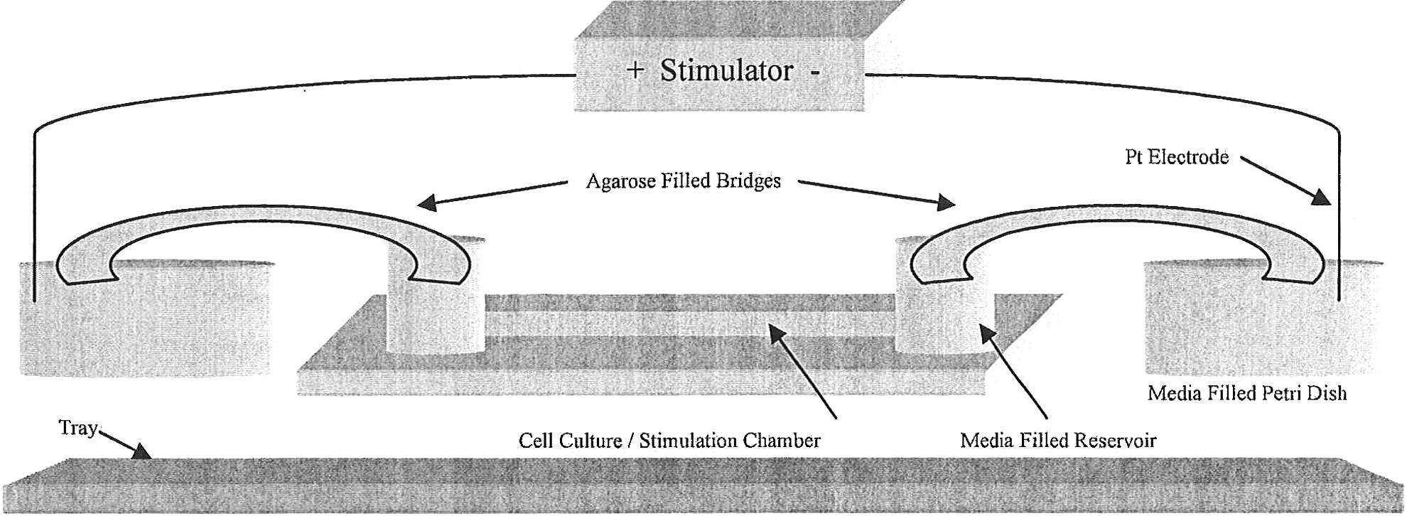
Schematic diagram of incubatable setup. The setup includes the stimulator, platinum electrodes, agarose-filled bridges, medium-filled petri dishes, cell culture/stimulation chamber, and foil-covered tray.
Results and Discussion
To test the effectiveness of the system, experiments were conducted to determine stimulator performance at 37°C and to examine its effect on a biological organism (Xenopus cells).
Stimulator testing
The stimulator's performance was assessed by monitoring the output current at the beginning and end of 16-h incubated runs and by comparing these two values to determine if there was a significant difference (Student's t-Test). Currents were set to 0.55, 0.84, and 0.88 mA. Six experiments were conducted at each current level (n=6). No significant differences were found at any of the values (ISET=0.55 mA, p>0.05; ISET=0.84 mA, p>0.05; ISET=0.88 mA, p>0.05). The 95% confidence intervals were also calculated for the beginning and ending output currents. Plots are shown for ISET=0.55 and 0.84 mA (Fig. 3). Currents were determined using Ohm's law after measuring the voltage across the series resistor (RSeries). Measurements were taken (from ports installed on stimulator) with a digital multimeter immediately after the system was removed from the incubator.
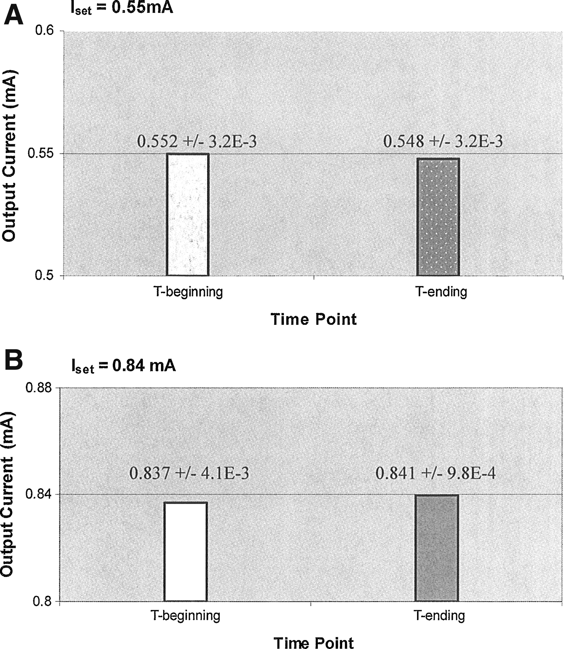
Comparison of stimulator output currents at beginning and at end of stimulation runs. Current stability was observed at each value tested with no significant differences.
Separate experiments were carried out to monitor the output current at several time points during incubated stimulations (Table 1). Readings were taken at 2 to 3-H intervals during the 16-h period. Comparable values were observed during the course of the runs. Results indicate that the stimulator performs well under incubator conditions and delivers a regulated current to the load.
Output Current Readings Taken Over a 16-h Period at 2 to 3-h Intervals
Output current regulation at 37°C.
SEM, standard error of the mean.
Xenopus cell stimulation (effect on a biological organism)
Xenopus cellular alignment and orientation were observed after electrically stimulating the cells with our system on the benchtop. The neurons and myoblasts were exposed to EFs of 120 mV/mm for 10 h. Phase-contrast photos were taken on a Leica DM IRB inverted microscope at the end of the stimulation period. Results were calculated and compared to that reported in the literature.2,7 Neurites (Fig. 4) and myoblast (Fig. 5) exhibited the cathode-oriented and perpendicular-like behaviors, respectively, described. Neurites were categorized in a manner similar to Rajnicek et al. 7 Namely, with the cathode at 0° and anode at 180°, neurites were classified as projecting cathodally if the X-coordinate of the growth cone was greater than the X-coordinate of the somal initiation site of the same neurite. Myoblasts were considered perpendicular if their bipolar axis was >60° with respect to the EF vector.

Xenopus neuron after 10 h in a 120 mV/mm electric field. Neurites labeled “c” are oriented or have turned cathodally. Magnification, 20×. Scale bar=50 μm. +/− signs indicate the field vector.

Xenopus myoblast after 10 h in a 120 mV/mm electric field. The elongated cell has its bipolar axis oriented in a perpendicular manner (63.4°) to the field; magnification 20×. Scale bar=50 μm. +/− signs indicate the field vector.
Mammalian cell stimulation
Rat cortical neurons were cultured in the Ibidi chambers and electrically stimulated with the incubatable stimulator developed. Neurite orientation and enhanced neurite extension were observed (to be reported separately), suggesting an influence by the field. Figure 6 shows a healthy culture of the cells after stimulation. GAP-43 staining confirmed that the cells were in a growth state. The abundance of neurites (highlighted by arrows), robust somas, and GAP-43 suggests that no ill effects occurred from stimulation.

Mammalian cell stimulation. Rat cortical neurons were stimulated with the incubatable system for 20 h at 200 mV/mm. The prevalence of neurites (featured by arrows) and somal morphology seen indicate that the cells were healthy after stimulation. Subsequent verification was performed with GAP-43 staining; magnification 20×. Scale bar=50 μm. +/− signs indicate the field vector.
One advantage of the system is that the current does not require constant monitoring. The performance test results (Table 1; Fig. 3) showed that the stimulator operates in a 37°C environment without any significant change in the output current. The circuit configuration cancels the temperature-dependent properties of the LM334Z, and thus provides current stability. Another advantage is that for mammalian cells, a traditional CO2 incubator can be used. This was found to be advantageous in our study of CNS neurons. It simplified the experimental process and procedures and facilitated obtaining consistent results.
Footnotes
Acknowledgments
Funding was provided by the Arizona Biomedical Research Commission (0017) and Weldon School of Biomedical Engineering, Purdue University, West Lafayette, IN.
Author Disclosure Statement
No competing financial interests exist.