
Abstract
Hollow-core 3D printing (HC3DP) proposes a new method for the production of lightweight, material-efficient thermoplastic 3D printed elements. This new fabrication approach promises material savings of 50–80%, while increasing the extrusion rate significantly (factor 10). This development pushes HC3DP to a similar fabrication speed as high-resolution concrete 3D printing. However, fundamental research on printing features enabled by this novel 3D printing approach is missing. Therefore, this article investigates printing with user-controlled bead dimensions (same nozzle, different size). It is showcased that the size of the extruded cross-section is determined by the positive air pressure used to inflate the beads. Multiple samples are printed, changing the layer height and width significantly without making changes to the hardware setup. Sections of 3DP samples are analyzed and the parameters of 3DP beads are determined. Furthermore, a set of bespoke 3D printed nozzles is introduced to subdivide the HC3DP beads into distinct areas. So far only regular beads, such as hollow tubes, have been used for 3D printing. Samples of those bespoke sections are analyzed to investigate their behavior when used for 3D printing. Finally, large-scale 3D printing experiments are conducted to investigate how printing features like bridging, cantilevering, or nonplanar 3D printing can be manufactured with hollow extrusion beads. In summary, this article provides insights into the fundamental 3D printing behaviors of HC3DP, showcases new design possibilities with bespoke and variable cross-sections, and finally proposes new research trajectories based on the findings presented.
Introduction
Large-scale material extrusion (ME) is one of the most popular additive manufacturing methods across all industries due to its affordability and large variety of available material.1,2 However, the existing large-scale 3D printing systems typically produce material-intense components because of the large size of nozzles and the necessity of thick extrusion widths for fabrication stability and warping prevention. Furthermore, the printing speed of large-scale ME is limited by the cooling rate of the extrudate more than the capacity of the extruder. 3
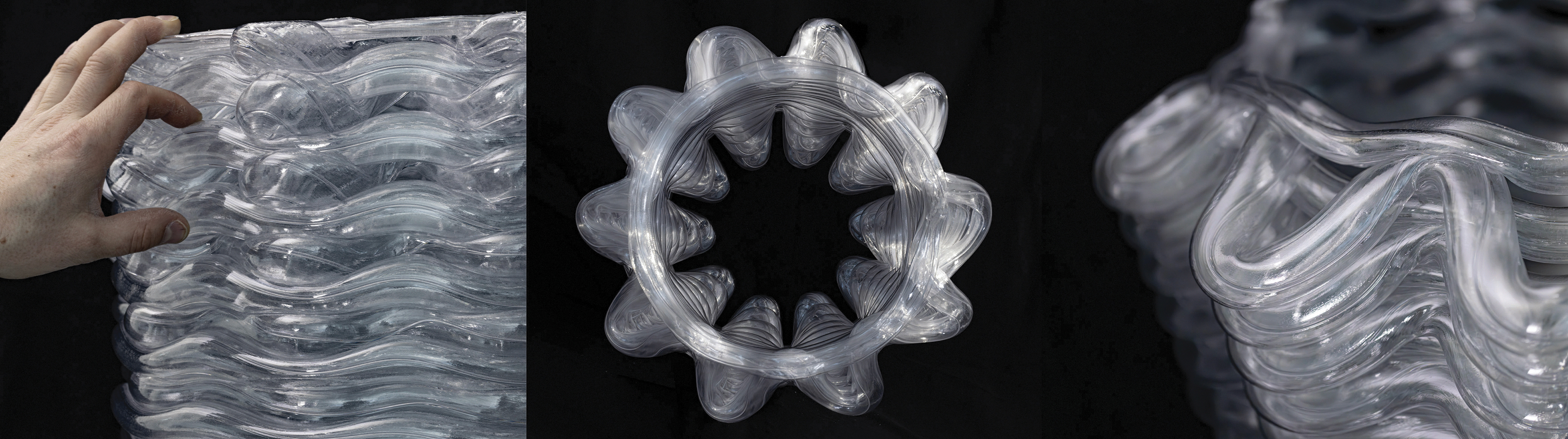
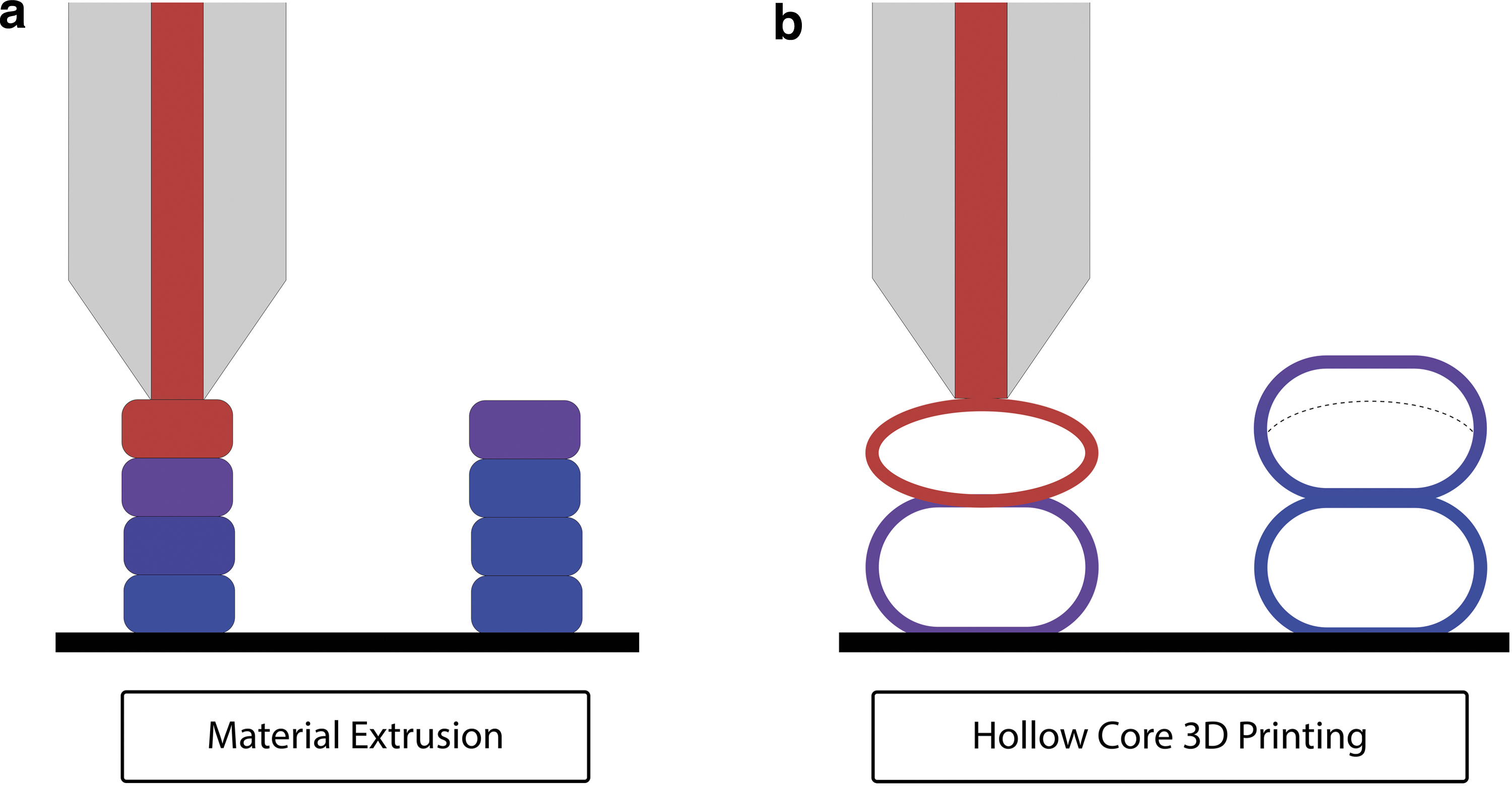
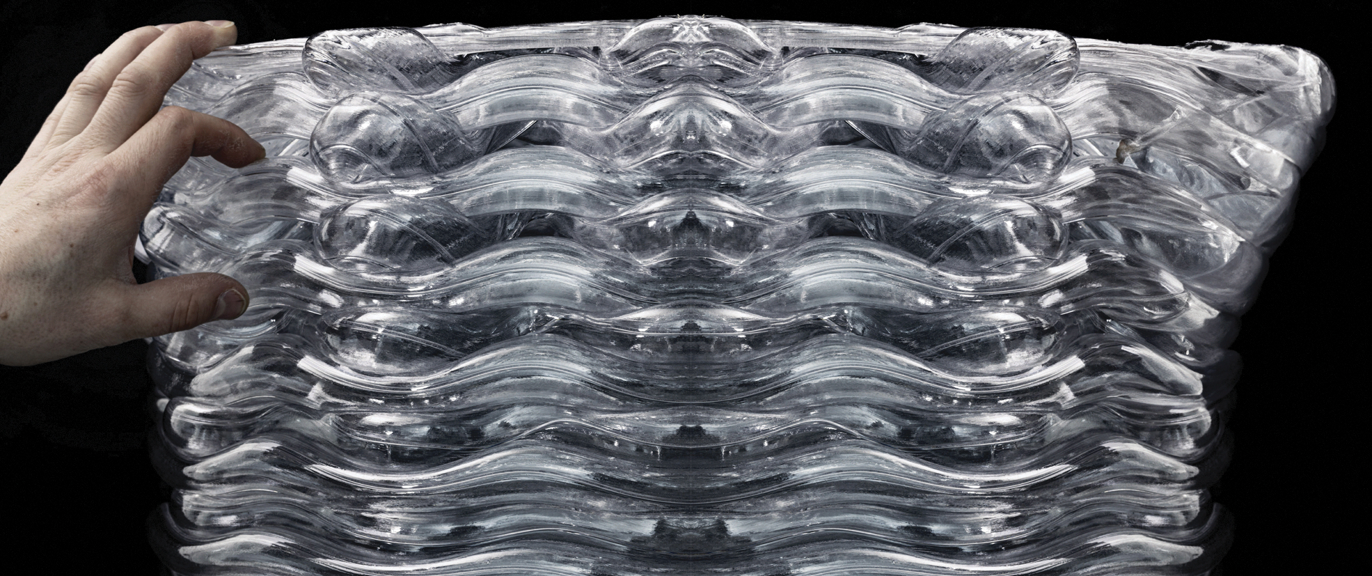
Large-scale hollow-core 3D printing (HC3DP) overcomes these major limitations and enables the production of large-scale, lightweight elements, while using only a fraction of the material by extruding hollow beads (Fig. 1). 4 HC3DP, with its tubular bead structure, holds the potential for great variation in layer height and printing resolution. By injecting air with a user-controlled pressure into the bead's core, the printed section can be controlled. Furthermore, due to the size of the extruded hollow bead, it is possible to introduce internal structures, which has not been investigated before. Furthermore, to this date, there is no investigation that explores the printing features of those low-resolution, large-scale polymer prints.
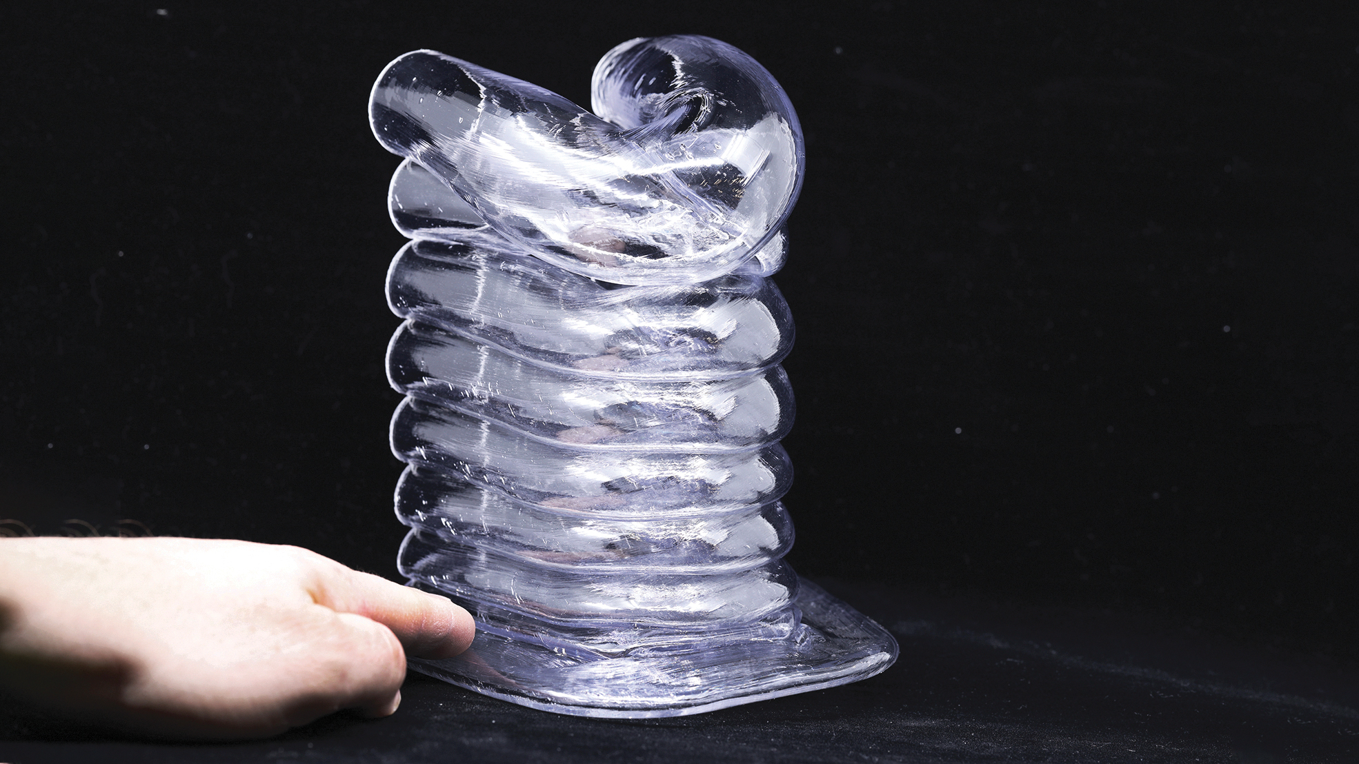
Large-scale HC3DP samples. Layer height 18 mm, layer width 24 mm. HC3DP, hollow-core 3D printing.
This article contributes to the state of the art by introducing variable extrusion sections in the range of 16–32 mm for HC3DP without introducing changes to the hardware. In addition, three different die geometries with internal substructures are introduced. To provide first insights on the printing behavior of these two parameters (layer height and die type), the sections of HC3DP beads have been analyzed for a series of experiments. Finally, investigation on bespoke toolpaths explores printing features, such as the bridging and cantilevering behavior of HC3DP elements.
State of the art
ME has, since its invention in 1989, 5 become one of the most used 3D printing methods worldwide.6,7 One of the latest trends in ME is the incremental advancements in increasing extrusion rate to reduce fabrication time. The extrusion rate of filament-based extruders was improved by extending their heating zone, increasing heating power, or combining multiple extruder units to feed into one nozzle.8–10 However, the extrusion rate of filament-based systems (∼0.5 kg/h) is not sufficient for manufacturing large parts (>1 m3) economically.
Therefore, pellet extruders have been introduced, which rely on pellet/granular feedstock, similar to injection molding machines. Those pellet extruders are specifically designed for extruding thick beads at high extrusion rates, which reach as much as 50 kg/h. 11 Pellet extruders are often mounted on six-axis robotic arms that provide a large-build volume (>1 m3). Scaling up ME using pellet extrusion systems dates back to 2011. 12 A large body of research focuses on technical advancements like material behavior, layer bonding, design guidelines, and bridging behavior.11,13–16 ME has been used for various projects and prototypes like formwork, temporary pavilions, or facades.17–22
Minimizing the fabrication time of large-scale ME has also been addressed from a computational design perspective. To create elements as time-efficient as possible, different layer heights/resolution can be used. One can distinguish between areas to print in low resolution to build up volume fast, and high resolution where details are needed. Changing printing resolution significantly (50% or more) during the printing process requires a multi-toolhead 3D printing setup, 23 multi-robot setup, 24 an automatic tool changer, or manual swapping of nozzles. For pellet-based ME, Chesser et al. have introduced an actuated nozzle design that can switch between two different die extrusion diameters. 14
Finally, for complex elements, overhangs and such typically support structures are needed. Those, depending on the printing geometry, can take up a significant amount of printing time and material. Especially, for large-scale ME, this is to be avoided. One way to reduce the amount of support structures, or to get rid of it entirely, is to use nonplanar 3D printing. In nonplanar 3D printing, the layers are not structured in a simple 2.5-dimensional manner, but layers can be defined freely in XYZ space and allow greater overhangs to be printed. 25
However, even with all those developments, the maximum print speed for large-scale ME (extrusion rate) is not limited by the performance of the extruder (hardware) or the optimal toolpath planning (software), but by the cooldown of the prior extruded layer. The cooling rate of the bead (extruded plastic strands), becomes more critical as the bead size increases. Larger beads take longer to solidify because their volume increases faster than their surface area, slowing down heat dissipation due to the surface-to-volume ratio. 3
The extrusion of thermoplastics to form tubular structures like pipes, tubes, or window-frame profiles is known in the industry as die extrusion.26,27 This manufacturing approach has recently been adapted for 3D printing and enables the fabrication of 3D objects based on hollow beads. To the best of the authors' knowledge only two precedents exist; for small-scale filament-based extrusion28,29 and Leschok et al. for the extrusion of bead sizes of over 20 mm using a pellet extruder. 4 HC3DP, at large dimensions, scales up ME, while addressing the most pressing limitations: material cooldown, material efficiency, and fabrication speed by 3D printing tubular beads/roads instead of solid ones. In this article, variable sections and cross-sections with internal reinforcements, as well as printing features like bridging and nonplanar printing are investigated.
Materials and Methods
Large-scale ME
A robotic setup for large-scale ME using granular feedstock involves several components and steps. 30 The extruder, mounted on the robotic arm, is responsible for melting and depositing granular material into the desired 3D object. The extruder generally consists of a motor with a gearbox, a heated barrel with different heating zones, a screw mechanism to move the material forward, and multiple heating elements to melt the polymer granules. The nozzle, at the end of the extruder, defines the size and shape of the extruded polymer bead. The nozzle size and design can vary depending on the desired printing resolution and the specific requirements of the printing process. A control system regulates various parameters such as temperature, material flow rate, and printhead movement.
The robotic arm provides precise control over the movement of the extruder, enabling intricate and complex printing patterns. With its six degrees of freedom, the robotic arm can manipulate the extruder in various directions, allowing the creation of bespoke geometries and curved surfaces. Finally, a granular feedstock is required, which must be dried before 3D printing. A material handling system is necessary to handle and deliver the granular feedstock to the printing system. This handling system typically includes storage containers, dryers and mechanisms like hoppers, or conveyors to transport the material to the printing unit.
Hollow-core 3D printing
To 3D print hollow-core beads instead of regular ones, adjustments to the aforementioned fabrication setup need to be made and have been described by the authors in detail in a previous publication. 4 The two major adjustments are, changing the nozzle to a hollow mandrel supported by spider legs, which splits the molten plastic into a thin wall and empty core, and positive air pressure to keep the hollow-core bead inflated. For the experiments described in this article, an ABB IRB 6700 industrial robotic arm with a pellet extruder system from SAEKI Robotics is used (Fig. 2). A 2 × 1 m wooden plate serves as a print platform and allows for easily fixing the printed object during printing experiments.
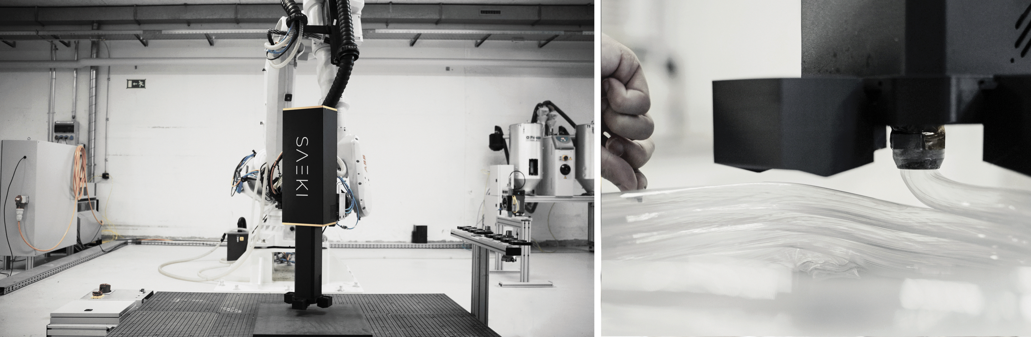
The 3D printing setup includes ABB IRB6700, a pellet extruder, a control cabinet, and a material handling system. Right: Close-up of the printing process.
For the experiments in this article, several die geometries are presented. They have an outer diameter of 24 mm and display varying wall thickness and internal subdivisions/reinforcements. Table 1 provides detailed information regarding the different nozzle types, material cross-section, and ratio of air to plastic. Those nozzle prototypes are manufactured with an Aluminum Alloy (AlSi10Mg) using direct metal laser sintering technology. The resolution of the printing process allows the fabrication of intricate and complex geometry at reasonable cost. The aluminum is sufficiently tough to be used in the prototypical 3D printing setup, while having good heat transfer for the molten pellets to maintain the necessary temperature for extrusion.
Comparison of Different Nozzles, Showing Area of Extruded Plastic and Internal Voids (mm2)
The nozzles are sorted by increasing the extrusion footprint.
Fabrication data and communication
Commercial software packages like AI built, Adaxis, or open-source developments like Compas Slicer allow the creation of robotic toolpaths for large-scale ME based on the 3D representation of a 3D model. However, these software packages do not create individual air pressure values for the HC3DP process, nor do they allow adjusting the toolpath for each individual layer, such as increasing overhangs or cantilevers used in this article.
Therefore, to have full control of the robot movements and to integrate different air pressure values, the toolpaths are generated with a custom script that produces a custom array of points. Each experiment will later describe the rules of the toolpath creation in more detail. The fabrication data are generated using a custom python script. The input is a list of points, velocities, tool orientation, speeds, and air pressure values, and each individual set of information per print point is exported into a JSON dictionary.
The communication between 3D printing setup and user is established by compasRRC, an online communication library for ABB Robots.
31
CompasRRC is able to read JSON dictionaries and send these data as robot code (RAPID) to the ABB robot. The information is sent to the robot includes the following:
position tool orientation speed zone, and a pressure value for each specific point.
This allows a high level of control over the toolpath and its materiality, and increases the stability of the HC3DP process.
Printing material and parameters
For the experiments presented in this article, polyethylene terephthalate glycol (PETG) modified is used. PETG is a popular material for 3D printing due to several key advantages it offers, like good chemical and structural resistance, and high transparency. 32 Before printing, the PETG was dried for 4 h at 60°C. While printing, the three heating zones of the extruder were set to 145°C, 175°C, and 205°C and the ambient temperature was 14.2°C. The most crucial printing parameters are robot speed, RPM of the extruder, air pressure values to inflate the bead, and the temperatures of the extruder. For each experiment, the values of those are provided. For all experiments, the authors print the first layer at a reduced speed (50%) to ensure good adhesion between the print platform and the printed object.
Sample design and fabrication
Two specimen types have been designed and printed for this research: First, a single-outline rectangular box with a footprint of 500 × 75 mm, and second, bespoke cylinders with a radius of 400 mm with varying height. The simple rectangular boxes are cut by hand using a fine metal blade and double-sided custom guide, and the sections are analyzed. The complex cylindrical geometries are designed to investigate the behavior of printing features at large dimensions. The focus here lies in creating cantilevering structures, observing bridging behavior, and testing nonplanar 3D printing.
For all specimens, the following design principles are considered:
Continuous toolpath, no start and stop, and no individual printing islands
Blend between individual layers, no straight z movement upwards
No self-intersecting toolpaths
Blend radius for corners/minimal feature size
Variable cross-section
The footprint of the printed samples is 500 × 75 mm and the height of the elements varies; at least seven layers are printed. The single outline toolpath is chosen, as it allows a stable printing process and a fast cooldown (fast fabrication time). Furthermore, the single outline print eliminates interface interactions between different beads within the same layer.
The distance between the layers (resolution in Z direction) varies for every print. The experiments start with a layer height of 16 mm and increase in 2 mm steps until a layer height of 32 mm is reached. Although the layer height is not limited to 32 mm, it is beyond the scope of the article to define the maximum printable layer height for the given fabrication setup.
All samples are fabricated with identical printing parameters, only the layer height and internal air pressure are changing. For each experiment, the internal air pressure is gradually increased to adjust the size of the extruded bead.
Static printing parameters are as follows:
temperature: 145°C, 175°C, and 205°C.
robot speed: 12 mm/s.
extrusion rate: 90 RPM.
Sample preparation and measurements
After printing, the samples are cut by hand using a fine metal blade and a custom double-sided guide. Cutting with electric devices holds the risk of damaging the part, as the polymer is heated beyond its melting temperature and debris might stick to the sample.
The sections are 2D scanned using an EPSON Perfection v39 with a resolution of 600 DPI.
ImageJ 33 was used to analyze the sections and determine the center point (c) of each bead. Then, for each individual bead, the vertical distance between layer interfaces (hc) and the width at the center of the bead wc, as well as the maximum width of the bead wmax are measured. Furthermore, the wall thickness at several points (rx), see Figure 3, is measured. Finally, the widths, heights, and wall thicknesses for each specimen are averaged to understand the trends in wall thickness, layer width, and the width to height ratio. The first printed layer is not included in the measurements, as it is connected to a second outline printed (brim) to increase the adhesion to the print bed (Fig. 7).
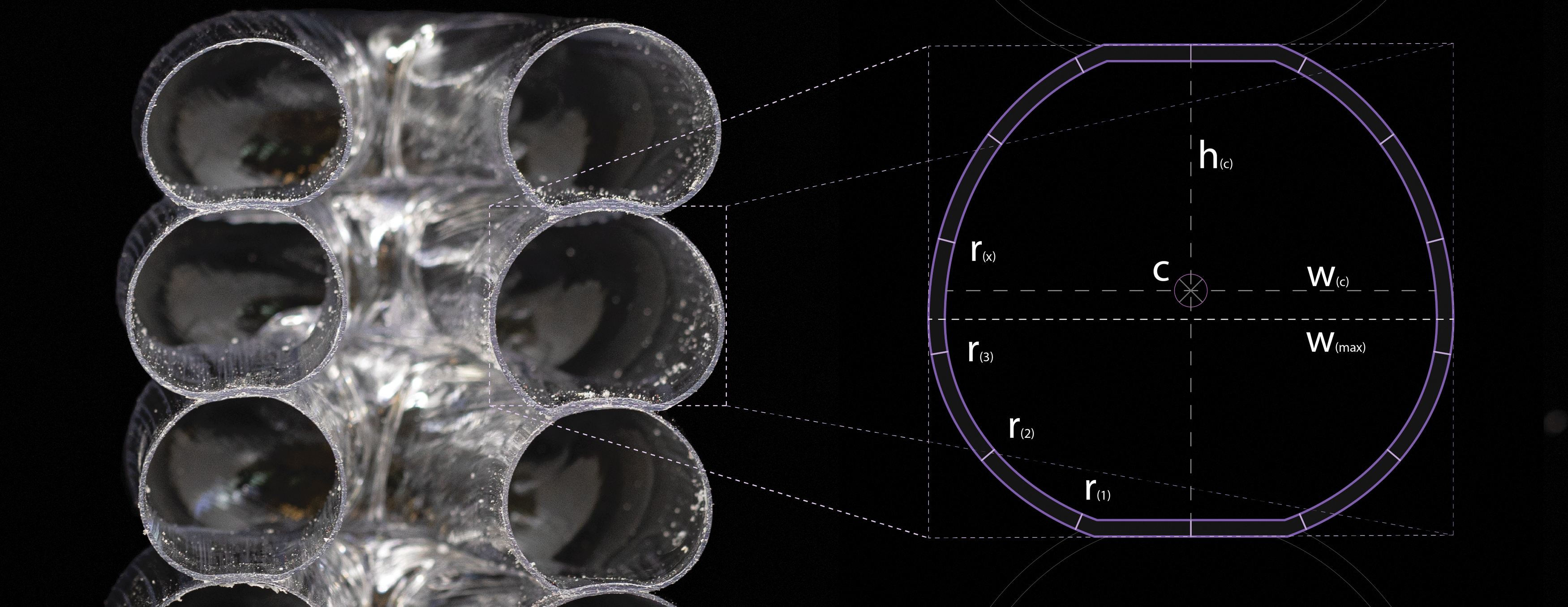
Close-up of a section, layer height 24mm and diagram of measurement points. c: center point, determined by ImageJ. h(c): height at point c; w(c): width at point c; w(max): maximum width, determined by ImageJ bounding box; r(x): wall thickness at point x.
Different nozzles: Internal geometry
The increased dimension of the 3D printable bead offers the opportunity to create subdivided die geometries. Those internal substructures can potentially improve the properties of the printed component in regard to structural, optical, or thermal performance (Fig. 4).
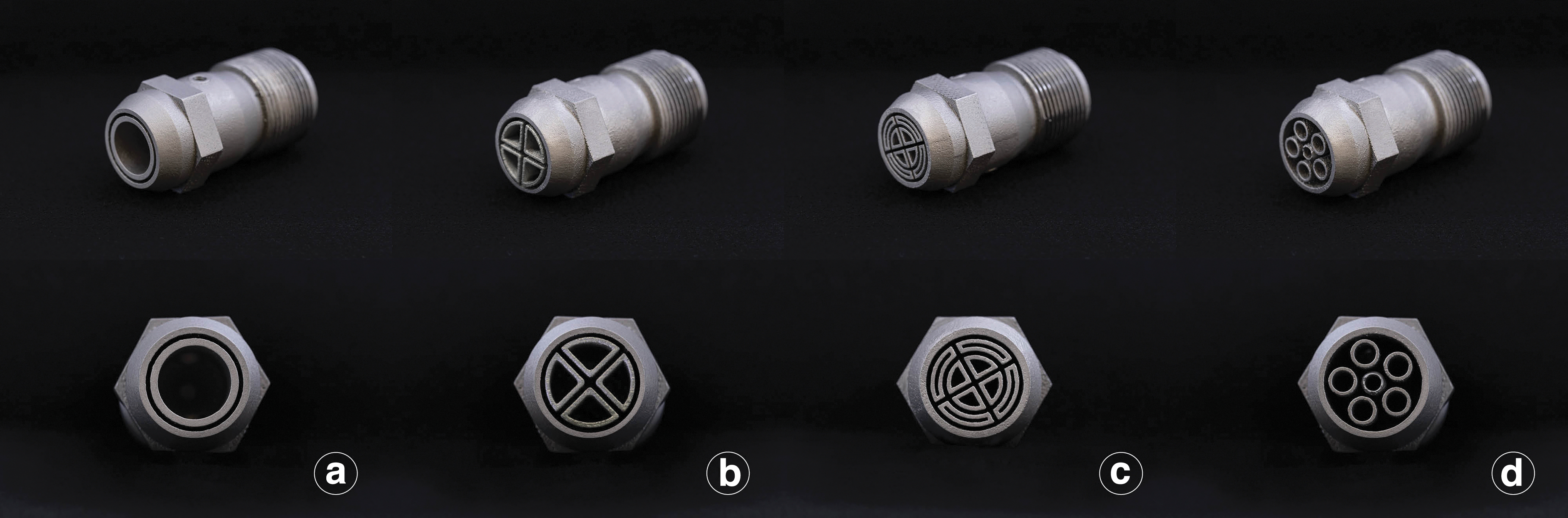
Different nozzles types, prototyped using 3DP of aluminum.
As a first attempt, four different die typologies are designed and fabricated. All nozzles have an outer diameter of 24 mm, (a) is a nozzle with no internal geometry, (b) contains a cross to reinforce the bead, (c) contains a crosshair pattern, and (d) consists of five individual tubes. Table 1 provides a detailed overview of the shape, pocket size, and plastic cross-section for each design. Similar to the experiments described in Sample Design and Fabrication section, basic rectangular elements are 3D printed and sections of the printed object are analyzed. This time, the wall thickness of the scanned sections (4800 DPI) is visualized using a color gradient, representing the minimal distance of a pixel to its closest border using the Rhino and Grasshopper environment.
Three-dimensional printing features
To provide initial explorations on printing features, several undulating cylindrical geometries with an average diameter of 400 mm are designed and fabricated. Those geometries are designed with the manipulation of points in either XY or Z direction of the base cylinder using the parametric design environment of Grasshopper. Three aspects of 3D printing are investigated: Cantilevering, bridging, and nonplanar 3D printing.
Bridging and cantilevering
Bridging describes segments of a print path that are only supported on their start and endpoint and not constantly supported from below. Researchers have investigated the bridging behavior for large-scale ME.15,16 Hopkins et al. showcased unsupported 3DP using small-scale tubular extrusion; however, their printing speed was limited to 0.8 mm/s. 29 The bridging behavior of HC3DP at large dimensions and regular printing speed remains unexplored.
Figure 5 shows the alternating print pattern that moves printing points in the XY plane away from the center of the cylinder, based on the points Z value/layer (from 3 to 8.8 cm). Two cantilever types are tested with this design, (red) straight bridging between two single supports and (blue) the unsupported print of a polyline.
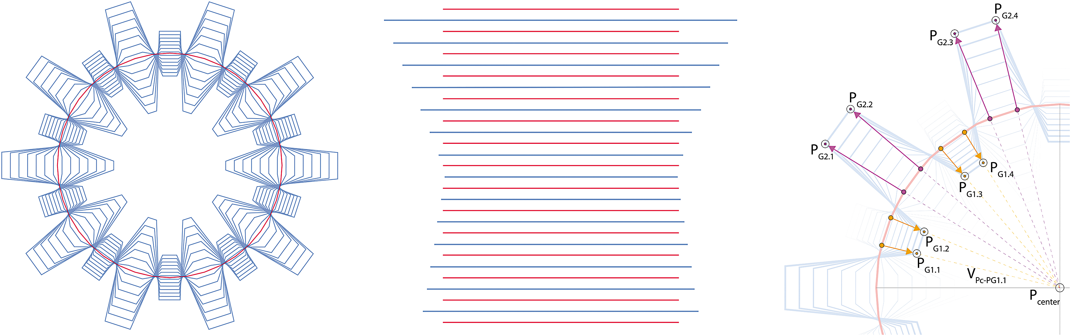
Bespoke toolpath with strong undulations in XY direction. Red represents bridges with a distance of 60 mm, blue indicates cantilevering areas.
The base circle is subdivided in 40 equally long segments, defining 40 points on the polyline. Each layer N is defined by this geometry, see red lines in Figure 5. Then for every second layer, the list of points is divided into pairs, creating two lists of points (group 1 orange and group 2 pink). The translation is defined by the vector V starting from the center point, the layer P-center, and each individual point PG.X. The distance for each translation is defined by two ranges, −100 to 100 for group 1 and 40 to −40 for group 2. Depending on which group a point is associated to, it moves either inwards or outwards depending on the current layer.
Nonplanar 3DP
Another set of experiments investigates the behavior of nonplanar 3D printing with HC beads. Figure 6 shows the toolpath, created similar to the aforementioned method. Print points of the base cylinder are moved, this time in vertical direction. The tool was kept at a constant frame/position during these initial experiments for easy programming.
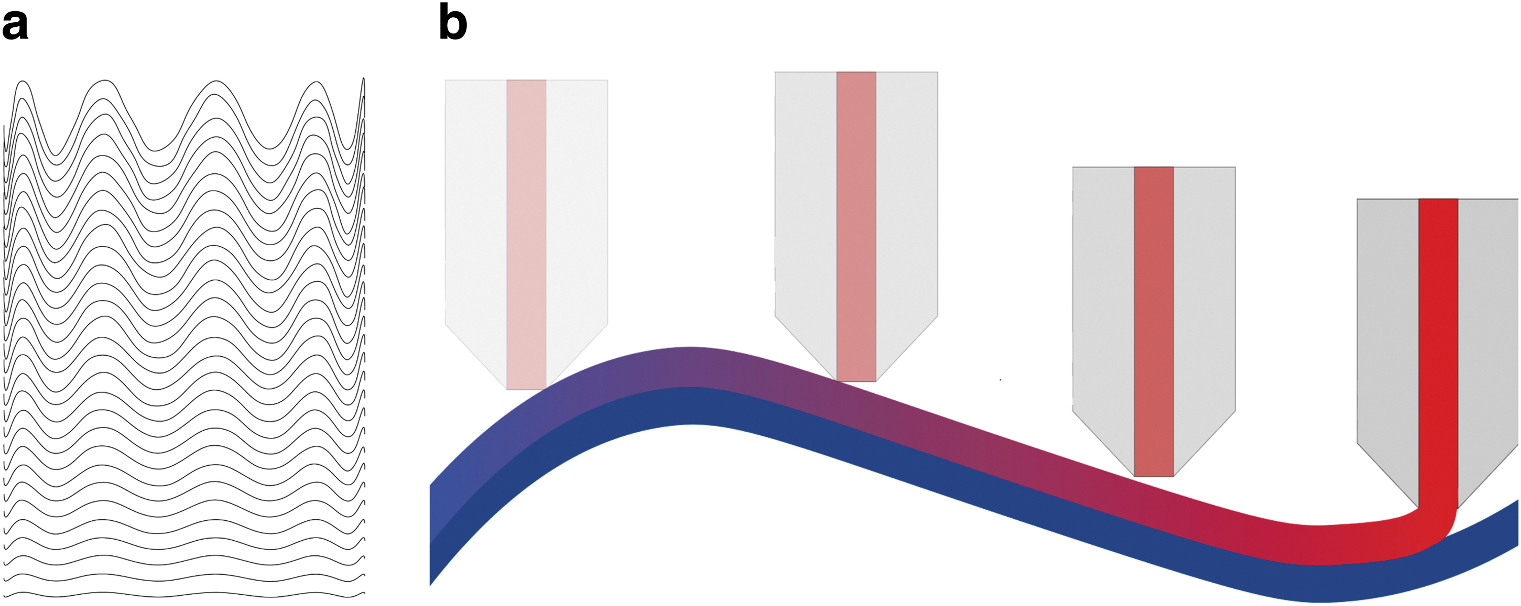
The toolpath is based on the identical subdivided circle, described in Bridging and Cantilevering section. This time, each individual point is moved in Z direction, perpendicular to the construction plane. The translation vector is defined by a sine function, whereas the frequency of this specific design is defined by a range from −1 to 9. The amplitude for each individual layer is remapped using a series of domains, with increasing range for increasing layer heights, starting from −3 to 3 for the first layer, to −47 to 46 for the last layer.
Results
Variable cross-section
The results show that it is possible to change printing resolution using HC3DP. The layer height was successfully changed from 16 to 32 mm without requiring changes to the hardware setup (Figs. 7 and 8).
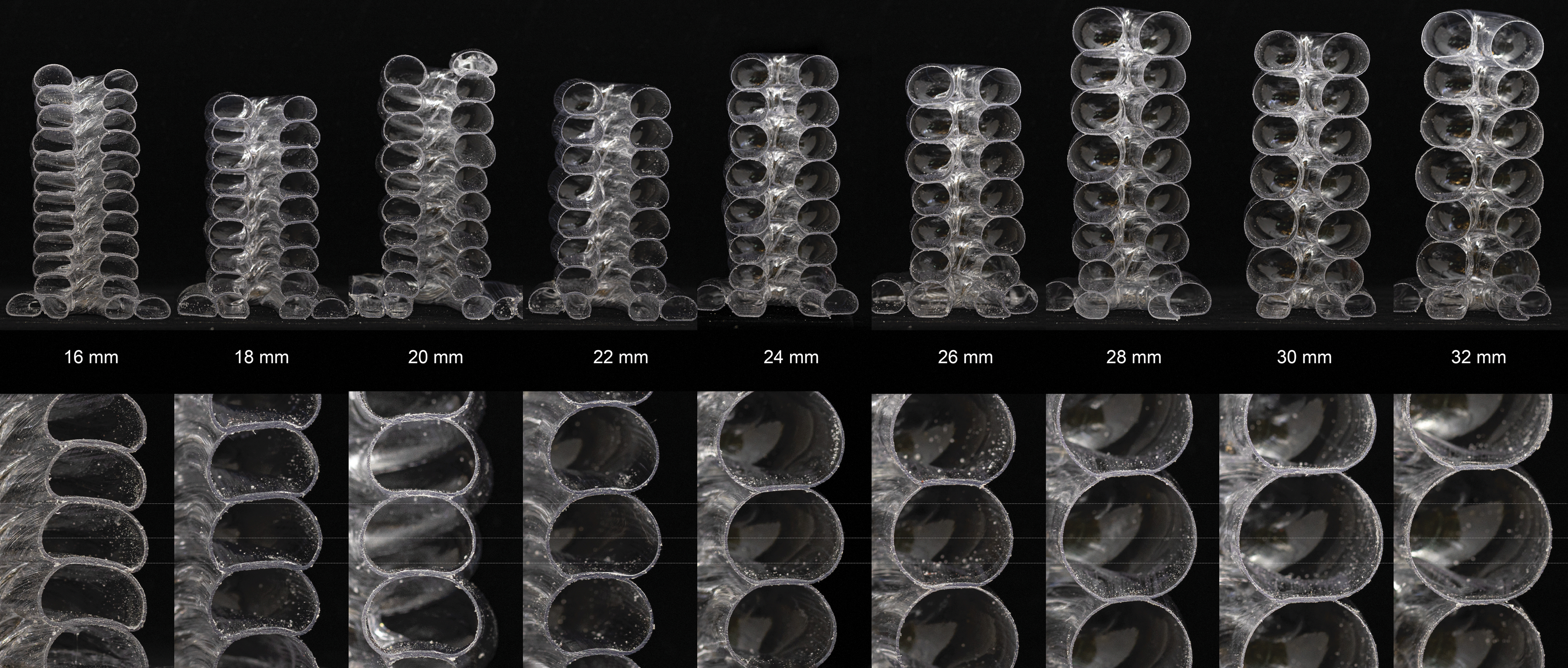
Sections of specimen printed with the same nozzle, but increased layer height.
Left: 16 mm layer height, right: 32 mm layer height.
The observations can be summarized as follows:
As the extrusion rate was kept constant, the wall thickness, as expected, becomes thinner with larger inflated beads.
The shape of the HC3DP bead changes from a rectangle with half-circular ends (low layer heights) to a nearly round shape for large layer heights.
The bead dimensions are not constant and become less consistent, the higher the layer height. Partially, this can be explained by the adjustment of air pressure during the experiments.
The increase in height always goes in hand with an increase in width, because of the uniform inflation of the core
Table 2 summarizes the measurements and provides the average dimensions for each layer height. There are clear trends in increasing layer width, reducing wall thickness, and reduced ratio of width to height.
Summary of Changing Printing Resolution
All parameters are kept constant, only the pressure increases.
Different nozzles: Internal geometry
The authors successfully 3D printed specimens using all nozzles with bespoke internal substructures. For doing so, a new concept of differentiated air pressure per print point needed to be introduced. 4 Figures 9–11 document the sections of the different nozzles; the scans generally show the following:
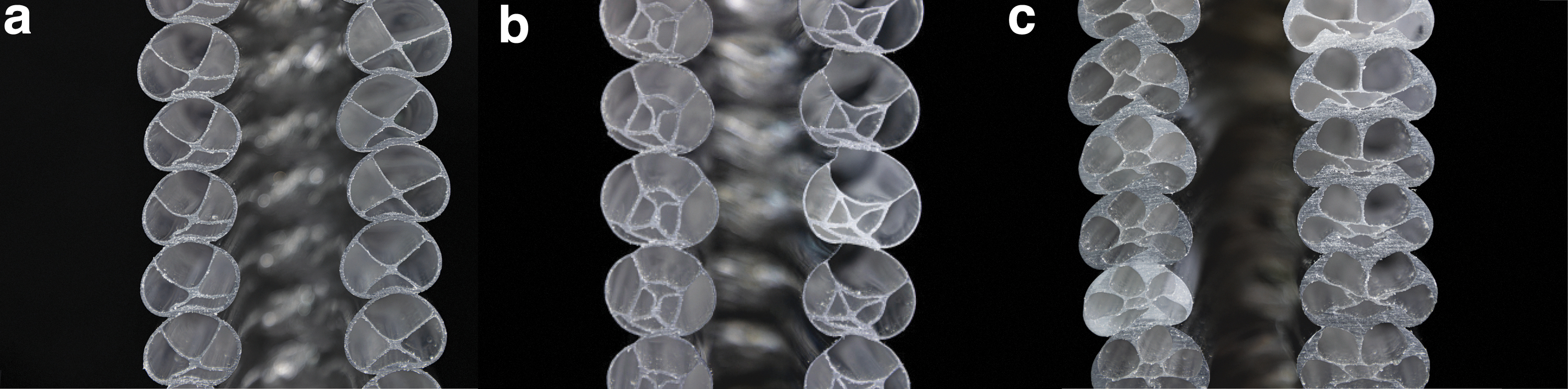
Section of 3D printed samples.
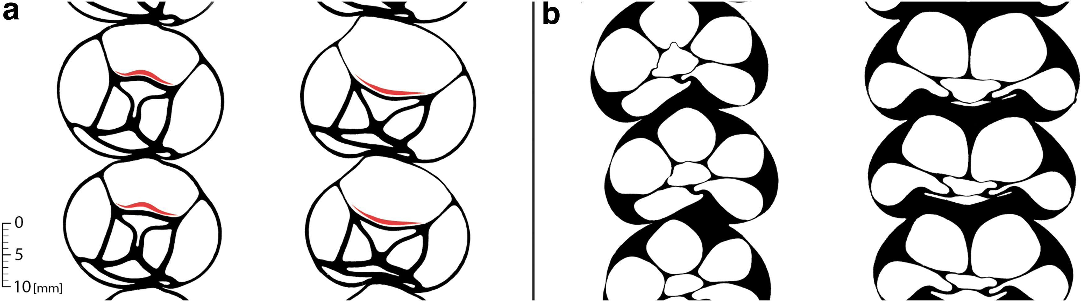
Two-dimensional scan of the bead cross-sections, printed with static tool orientation. Left and right specimen printed in linear motion with static tool orientation (transverse to the printing layer) from point A to point B and B to A respectively.
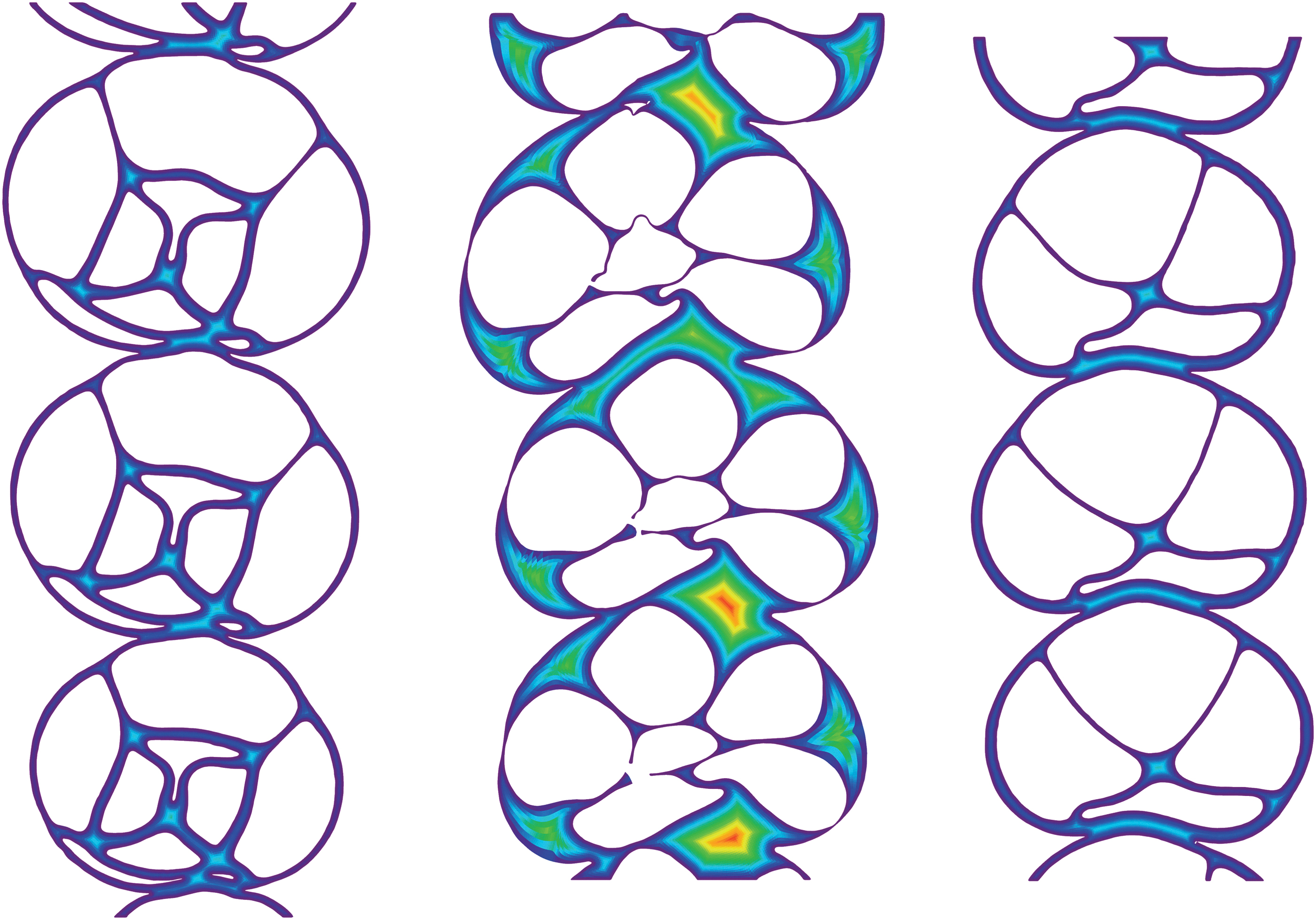
Visualization of the material distribution in the HC3DP beads, the color gradient displays the distance from a pixel to the closest border.
all die geometries can be used for 3D printing
there are deviations in the bead geometry, between individual layers and from one wall to the other
the deviations are more significant for cross-sections with more material/unequal wall thicknesses
The lower air pockets, interfacing with the previous layer, are less inflated than the corresponding upper air pocket
asymmetric die geometries create, depending on the tool rotation, different 3DP cross-sections.
The section of the crosshair nozzle is specifically interesting as it shows different internal deformation depending on the printing direction. As shown in Figure 10a, the internal ring shows either a convex or concave deformation (red stroke). This indicates that the pressure inside the single air pockets is not equally distributed. The design of the air inlets, or the manufacturing process of metal 3D printing, might be the reason for this phenomenon. For asymmetric die geometries (tube in tube), the cross-section of the printed bead changes for different printing directions if the tool orientation is static (Fig. 10b).
Three-dimensional printed features
Bridging and cantilevering
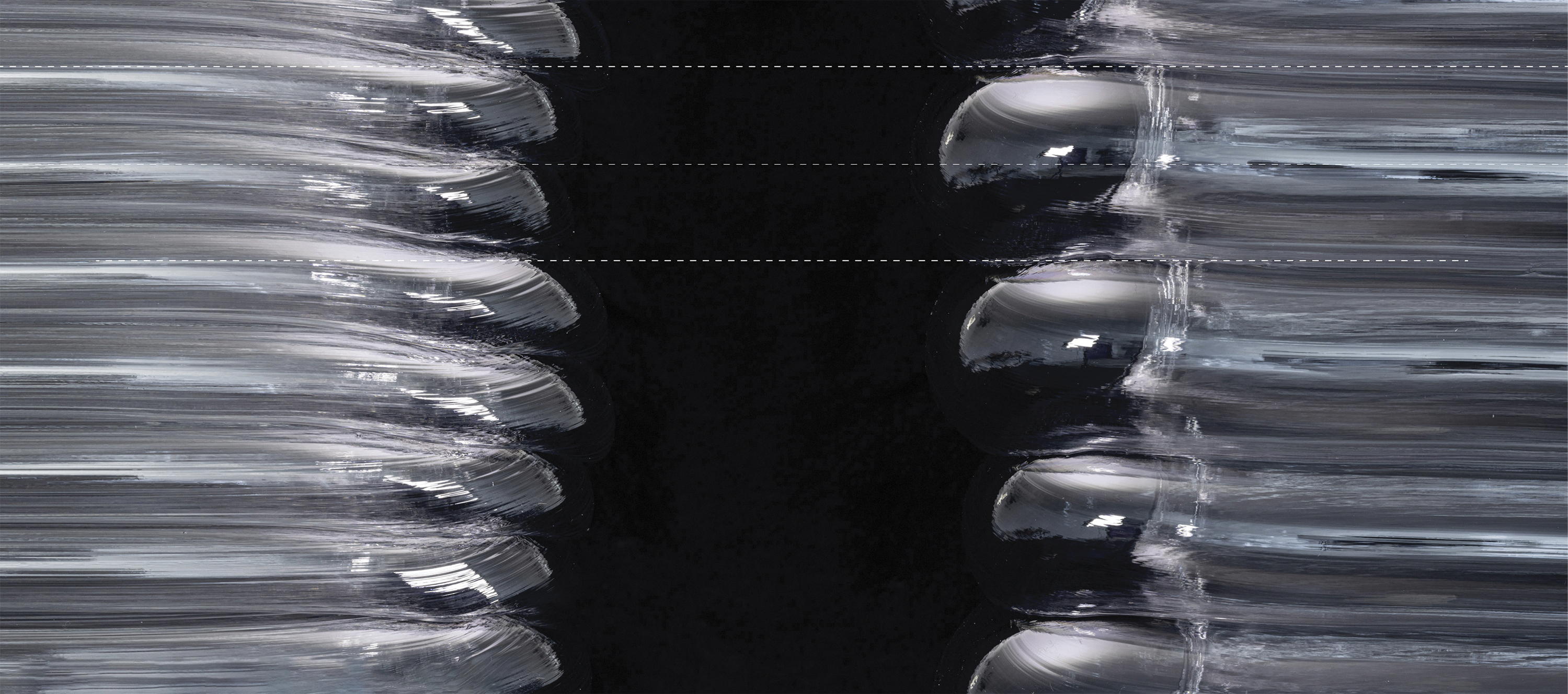
The results show that HC3DP bridges distances of 60 mm successfully at print speed of 12 mm/s, Figure 12a. However, the sagging behavior is observed to be different from common ME. As shown in Figure 13, the upper and lower sag are significantly different. The upper side of the bead sags ∼2.8 mm, the lower portion of the bead is sagging up to four times more, ∼12.2 mm. This difference can be explained with the active cooling that is reaching the upper side of the bead, but not the lower. The material exposed to forced airflow solidifies faster than the bottom area, which then stretches due to gravitational forces. For a more equal cooling, the current set of fans needs to be redirected to also hit the sides of the extruded bead, or external fans need to be set up.
Three-dimensional printed specimen overlaid with actual toolpath.
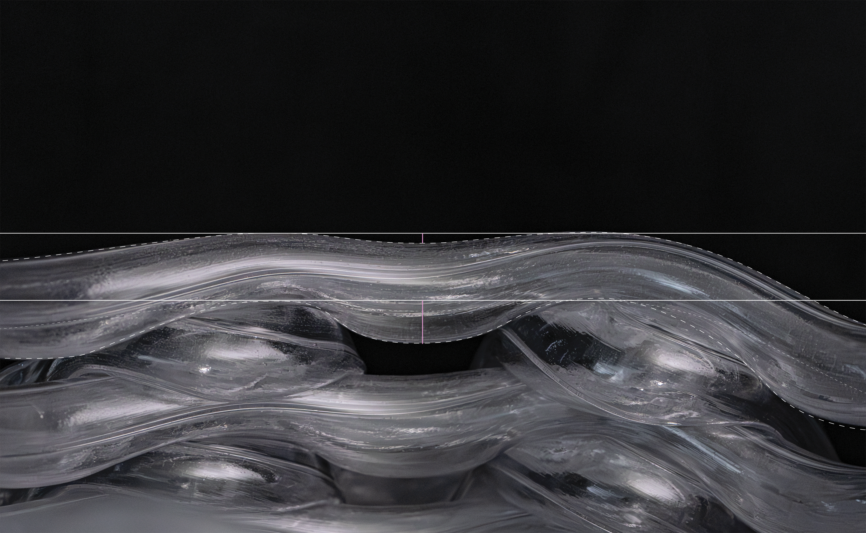
Sagging behavior of HC3DP during bridging.
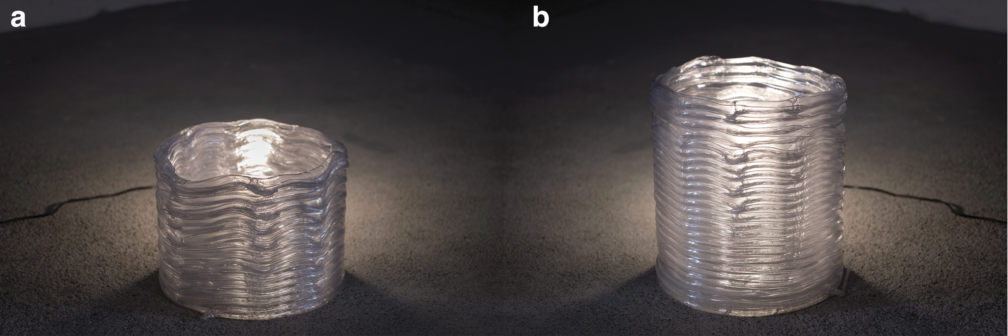
Printing in air cannot be reproduced with large beads at fast printing speeds, as shown in small-scale tubular printing by Hopkins et al. 29 However, the print does not fail, only strong deviations occur (Figs. 14 and 15). Although only every second layer is printing the cantilevering structure, the cantilever is still building up, with a maximum deviation of three layers missing. This can be partially explained as the beads that are not supported from below, and therefore not squeezed between the previous layer and the extruding nozzle. Those beads have a round and not a rectangular shape with half-circular ends, similar to the experiments in Variable Cross-Section section, and showcase a larger layer height than designed for.
Bespoke toolpath design for large-scale elements.
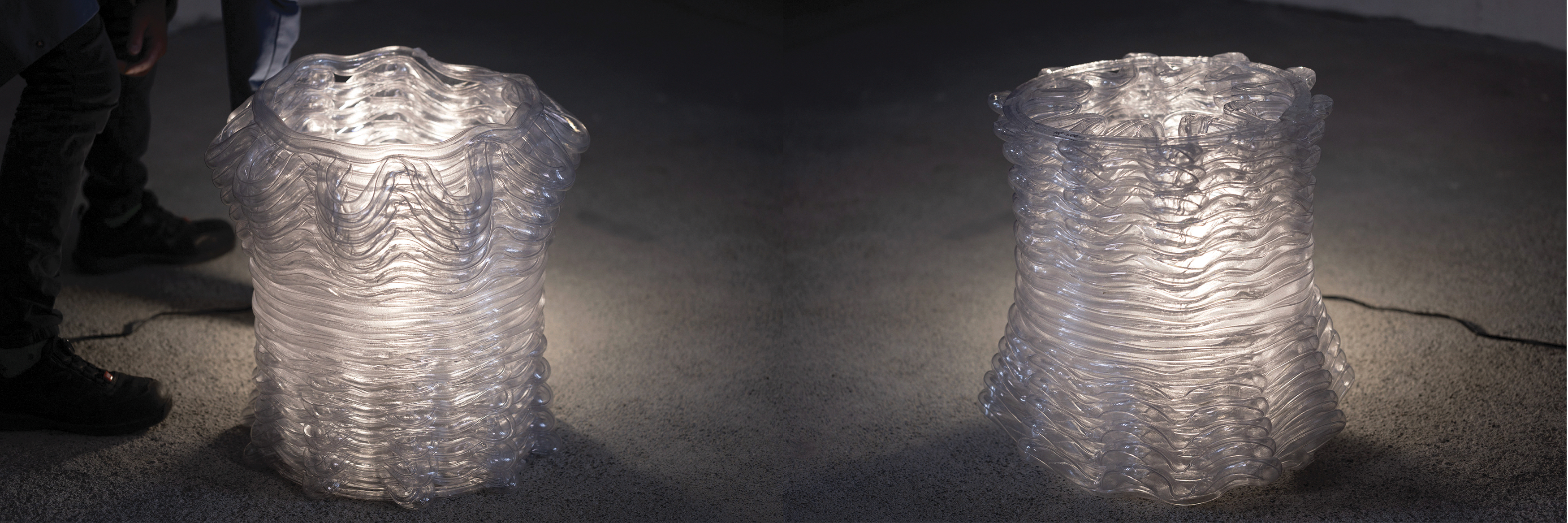
Large-scale specimen with a light source behind it.
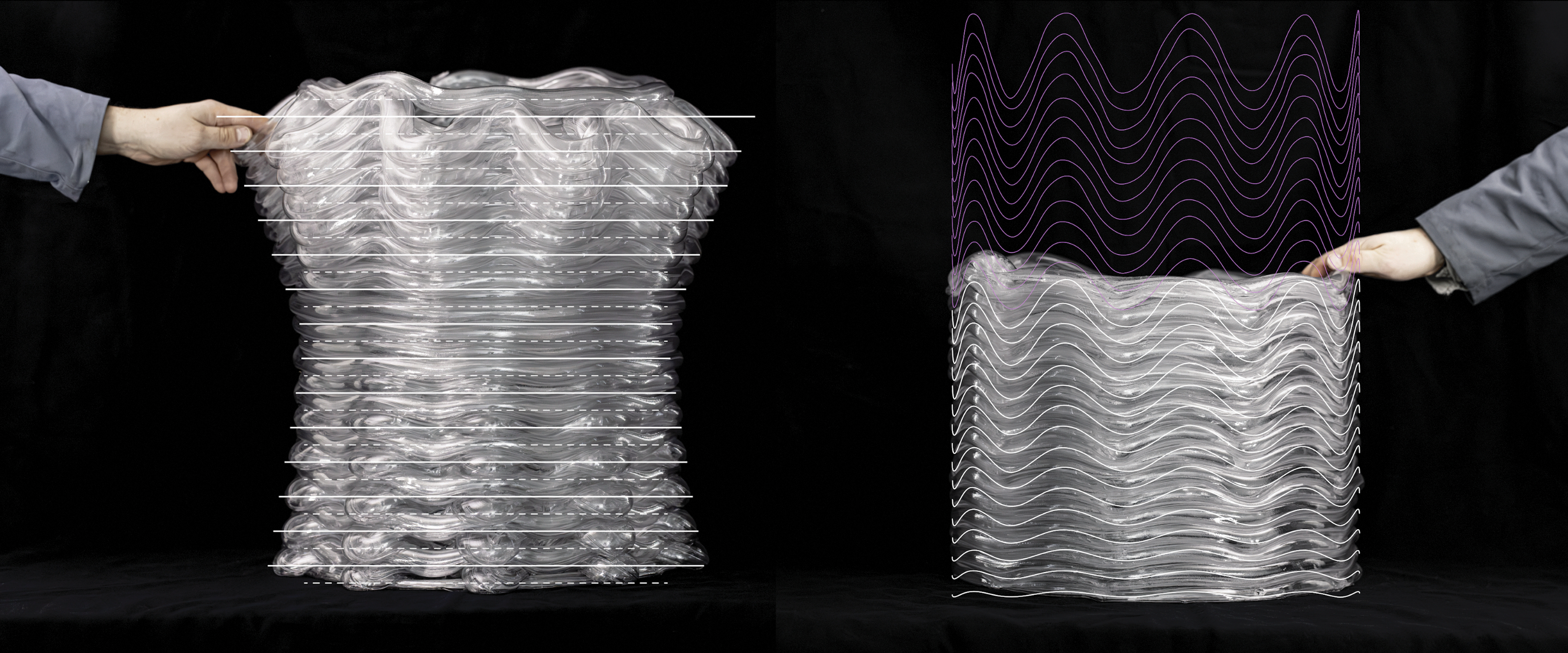
Nonplanar 3DP
Figures 12a and 16 show successful nonplanar HC3DP. However, as the tool was not reoriented during printing, collisions with previous layers caused the print to fail. It was observed that when moving the toolhead downwards, toward an already printed bead, the distance between nozzle and printed objects becomes too little for the tubular bead to be inflated. Instead, the hollow bead gets squeezed together and becomes solid. Then, when the toolhead rises to follow the trajectory of the toolpath, the distance between printed object and nozzle increases and the hollow-core bead is overinflating. This causes the consecutive layer to collide with the object and the experiment needs to stop after layer 15.
The observations are showcasing a different behavior than ME. Although the HC3DP layers can be squeezed down, the inflation of the bead continues once the extruder moves along the printing path (Fig. 17). This postinflation of beads results in strong deviation to the desired toolpath and remains a challenge for nonplanar 3D printing. More research is needed to fully understand the postprint inflation and achieve controlled results.
Postinflation diagram.
Discussion
Variable cross-section
Changing the extruded cross-section without changing extrusion rate has been successfully demonstrated. Whether the same result can be achieved while maintaining a constant wall thickness is still to be investigated. The difference in wall thickness measured in Table 2 can be potentially used to determine an extrusion multiplication factor. Controlling the layer height and the wall thickness precisely would increase the versatility of HC3DP and allow the fabrication of even more material-efficient components. To which extent these findings can be transferred to a multi-outline (contour) print is still to be investigated.
How to dynamically change the cross-section during printing remains unexplored. Although the hardware setup allows for it, the software will need to map pressure values to certain layer heights, similar to tight geometrical features. 4
Main benefits of dynamically controlling the cross-sections are, but not limited to the following:
increased print speed for fast vertical build-up in low-resolution HC3DP
more detailed areas can be printed in high resolution
stronger overhangs can be printed at low layer heights, as the stepover per layer reduces
Different nozzles: Internal geometry
The initial experiments with bespoke cross-section, although inflated, show deviations from the initial geometry. Further investigations need to clarify if the quality can be improved by tuning printing parameters, or if it is necessary to have differentiated pressure control for each individual air pocket. If individual pressure zones are implemented, these differences can be potentially counteracted. However, hardware/software requirements change, and the HC3DP nozzle and control system will increase in complexity.
Furthermore, there is a tradeoff between maximum print speed and the number of subdivisions, as internal geometries will increase material consumption. The maximum print speed will be determined either by the maximum extrusion of plastic or the cooldown rate of the extruded bead.
The benefits of subdividing the internal core, although a unique feature, must be investigated further for specific applications. Structural experiments are still to be conducted, as well as the potentially improved thermal resistance. Finally, it would be interesting to see to which extent adapting the extrusion section is possible with those bespoke die geometries.
3DP features
The fundamental behavior of HC3DP features has been presented in this article. With this understanding, a fabrication-aware design tool can be created to eliminate printing errors, and increase the ease of use of this novel printing technology.
Initial observations show an improved bridging behavior for HC3DP compared to state-of-the-art large-scale ME (Fig. 18), mainly due to the increased cooling rate of thin-walled beads. However, future investigations must quantify this trend to understand the dependency of print speed, bridging distance, and material.
Close-up of the bridging sample. Sample flipped.
Conclusions
The authors have proven that it is possible to change the extruded section by increasing/adapting the air pressure inside the bead. Multi-resolution 3DP can now be achieved without the need for a second extruder or additional hardware. Research on dynamically changing the extruded section is yet to be conducted.
The introduction of dies with purpose-made cross-section creates a new research trajectory for large-scale HC3DP. Tailoring the cross-section of the extruded bead introduces an additional parameter that can affect the functionality of 3D printed components, in addition to design and toolpath that are commonly considered. HC3DP at large dimensions provides the opportunity to create bespoke, noncircular, and such cross-sections that increase the range of possible applications.
Adaptive extrusion section control allows the creation of unseen designs, material efficient structures, and significant improvements on fabrication speed. With this article, the authors hope to provide fundamental understanding of this novel printing technology to foster more in-depth research, new design strategies, and production of material efficient 3D printed elements.
Footnotes
Acknowledgments
The authors would like to acknowledge Philippe Fleischmann for his technical support on the compass RRC communication and SAEKI Robotics AG for their time, dedication, and providing 3D printing capacities.
Authors' Contributions
Conceptualization: M.L. and B.D. Data curation: M.L. Formal analysis: M.L. and Y.F.C. Funding acquisition: B.D. Investigation: M.L. and M.K. Methodology: M.L. Project administration: M.L. and B.D. Software: Y.F.C. Supervision: B.D. Validation: M.L., M.K., and Y.F.C. Visualization: M.L. and Y.F.C. Writing—original draft: M.L. and M.K. Writing—review and editing: M.L., M.K., and B.D.
Author Disclosure Statement
ETH Zurich has filed a patent application: M.L. and B.D., Arrangement for Additive Manufacturing of a Structure, EU Patent Application EP22201353.4, filed 13 October 2022. M.L. is co-founder and COO of SAEKI Robotics AG, a company specializing in robotic large-scale additive manufacturing equipment used in this research. No other competing financial interests exist.
Funding Information
This research is financially supported by the National Centre for Competence in Research in Digital Fabrication, funded by the Swiss National Science Foundation (NCCR Digital Fabrication Agreement No. 51NF40141853).