
Abstract
Metal three-dimensional (3D) printing technology brings several benefits to the field of high-pressure die casting of aluminum, which enhances its development. The associated conformal cooling application is already commonly used where there is a need to improve the quality of castings, increase tool life, or reduce the production cycle. However, will this technology withstand the production of a large part (∼270 × 270 × 200 mm), which will be used directly in the serial production of engine blocks? This article describes a slider with a conformal cooling case study, which was redesigned and manufactured using the laser powder bed fusion (L-PBF) method. After the slider was put into serial production of 1.0 TSI three-cylinder engine blocks, this tool was thoroughly monitored based on the temperature field by comparing the results of a simulation in SW ProCAST with reality, and furthermore examining the influence of the tool on the quality of castings. There was also an evaluation of repairs performed on the tool in the ŠKODA AUTO tool shop and the foundry. These data were compared with a serial tool. Finally, the costs to produce the slider in conventional and 3D-printed variants are compared with an outline of other possible steps for optimizing these costs. The study results show that relatively large parts can be printed and used in serial production even today. It was also confirmed that conformal cooling influenced improving tool life, and the number of repairs in ŠKODA AUTO production also decreased.
Introduction
Progressive and modern metallic three-dimensional (3D) printing technologies are becoming more widely used in various industries. High-pressure die casting (HPDC) is one application where this technology is already relatively widely utilized. Hassen et al 1 summarize and interpret the results of the AMBA (American Mold Builders Association 2 ), which estimates that the market value of the mold and die industry will reach $ 368.5 billion by 2026. The authors also point to a drastic increase in 3D printing to increase productivity, reduce the production cycle, and reduce the cost of producing molds and tools. The use of conformal cooling is well-researched; however, this research is usually focused on smaller components of the tool such as cores and inserts, which are tested in a special mode, prototype, or small-series production.
The purpose of this article is to test an additively manufactured part of atypically large dimensions exceeding ∼200 mm along each axis in mass production, where the life of the tool part is expected to be more than 80,000 produced castings.
Some of the main advantages of additive manufacturing (AM), include freedom of design, waste minimization, mass adaptation, and the ability to produce lightweight structures as determined by Ngo et al. 3 Due to the limited working space of currently available 3D printers, it is not currently possible to entirely produce whole parts of molds (max 800 × 400 × 500 mm), and hence limited to creating smaller segments such as inserts and cores.4–6 Furthermore, modern powder bed technologies also suffer from limited workspace size and low productivity.4–6
Readers may consult references4–6 for a comprehensive overview of the materials used to produce these tools and a list of the most common failures of mechanisms in the HPDC process, which in summary are as follows: heat checking (thermal fatigue), erosion, that is, hot mechanical wear (velocity of the melt), metal corrosion (chemical interaction Al and tool material), cracking (mechanical overloading), soldering (molten alloy sticks to the shape), shrinkage porosity (bad temperature management), and cracking from the cooling channels (high stresses based on wrong channel design, residual stress, or chemical corrosion).
Additive technologies can offer significant improvements in heat distribution in the manufacturing of die-casting molds, namely, using conformal cooling and tool steel with a high thermal conductivity.7–9 Specifically, time efficiency is improved, more unused material can be reused and recycled. It is important to note that heat treatments performed after printing have negative effect on tolerances.
Armillotta et al 10 and Piekło and Garbacz-Klempka 11 report on an experimental study of the production of molds with conformal cooling using AM. Their main goal 10 was to compare the advantages and limitations of the application. The results show that conformal cooling improves the surface quality of castings due to a higher and more uniform cooling rate.10,11 Other advantages include shortening the cooling time and reducing the porosity. The tool was tested in production, where the mold underwent 2000 cycles, and the printed insert showed no signs of damage.
Stolt and Jarfors 12 present a similar study and describe the process of manufacturing a tool measuring 240 × 64 × 35 mm made by metallic 3D printing for HPDC. The decision to leave the dimensions at nominal values led to the destruction of the first set of tools, as the real dimensions were of the order of several mm smaller. This led the authors to introduce a +2% shrinkage compensation allowance, with which the tool had already been printed. Jarfors et al 13 partially confirmed and verified the results of Armillotta et al 10 of the use of conformal cooling produced by the metal 3D printing method.
An extensive review study on conformal cooling was conducted by Kanbur et al. 14 This was partly followed by Feng et al, 15 in their study on the design and manufacture of conformal cooling channels in molds, Brooks and Brigden, 16 Berger et al, 17 Wang et al, 18 and Minguella-Canela et al, 19 who were focused on optimizing the process of injecting molding. Authors showed positive results of conformal cooling, a reduction in cooling time of ∼30% compared with conventional cooling channels. Mazur et al 20 and Oter et al 21 decided to focus on the challenges of printing H13 and 1.2709 steel injection molds by selective laser melting.
Cortina et al 22 examined the design and manufacture of conformal cooling ducts, which are additively made of hot work tool steel and then milled to achieve the final quality. The results show that laser metal deposition (LMD) is a superior technology for creating conformal cooling, allowing the production of geometries that cannot otherwise be produced. Sinico et al 23 showed how the new thermal-limited topological optimization tool reduces heat accumulation, and the optimized design could be printed with greater accuracy without using local preheating.
Petrič et al 24 performed modification and redesign of the insert for HPDC based on simulations in SW ProCAST. By changing the cooling, 60% lower temperatures were achieved, and thus also lowering the stress loads on the tool. Based on these successes, the total tool life has been increased by a total of 36%. Fiorentini et al 25 presented two finite element simulations to analyze and compare the temperature, and the stress fields obtained on the insert with two different cooling systems and find out the better system that could limit the frequent substitutions of the inserts. The result was, analogously to the study, 24 a reduction of mechanical and thermal stress and a reduction of cycle time.
Malca et al 26 and Kang et al 27 compared new methods of optimization: lattice structure and lightweight shell. Lattice structures are helpful for injection molds, reducing weight by up to 58%. Experimental results revealed that the new sand mold design saved at least 60% sand and reduced shaking time by 20%. The hollow structure prolonged the solidification process by ∼15%. The three main problems that most commonly occur with the use of AM are as follows: designers using conventional design to design conformal cooling, lack of knowledge of design rules that should be followed when designing AM parts, and ignorance of mechanical loads and negative impacts by poor design choices.28,29 This is followed by another article, 30 which already shows a specific case study of an additively manufactured distributor applying conformal cooling, leading to a significant reduction in cycle time and increased tool life.
The aim of our investigation was to design and manufacture a large tool for HPDC using the laser powder bed fusion (L-PBF) method with subsequent use in real conditions of serial production. As mentioned in DebRoy et al, 31 the production of large parts on commercially available L-PBF equipment is difficult and sometimes impossible. L-PBF technology was chosen due to accessibility within the Volkswagen Group. Other technologies, such as direct energy deposition (DED), can offer better productivity in manufacturing large-scale parts than L-PBF, but the internal surface and cross-section geometry of cooling channels do not meet quality requirements.31,32 The authors find this an unexplored area because as already mentioned, 12 there are few publications on this segment.
Often, this topic is solved at the simulation level, for example, in Kanbur et al, 14 Feng et al, 15 and Fiorentini et al, 25 and the largest printed parts according to the state-of-the-art were, for example, ∅ 110 × 50 mm by Piekło and Garbacz-Klempka 11 or 240 × 64 × 35 mm by Stolt and Jarfors. 12 Furthermore, this article could serve as a case study to help open the chapter on 3D printing of large components and show that it is possible to produce parts at this size with this technology. However, due to the principles of L-PBF technology, it is necessary to consider specific problems (e.g., poorly chosen machining allowances and shrinkage compensation, 12 and workspace size limitations).4,5
The subobjectives that have been set are the following:
comparison of temperature fields in SW ProCAST tools concerning the method of cooling, influence of the tool on the quality of castings, the influence of the tool on the number of repairs in the tool shop and foundry, and comparison of actual costs for tool production (conventional production × 3D printing).
Materials and Methods
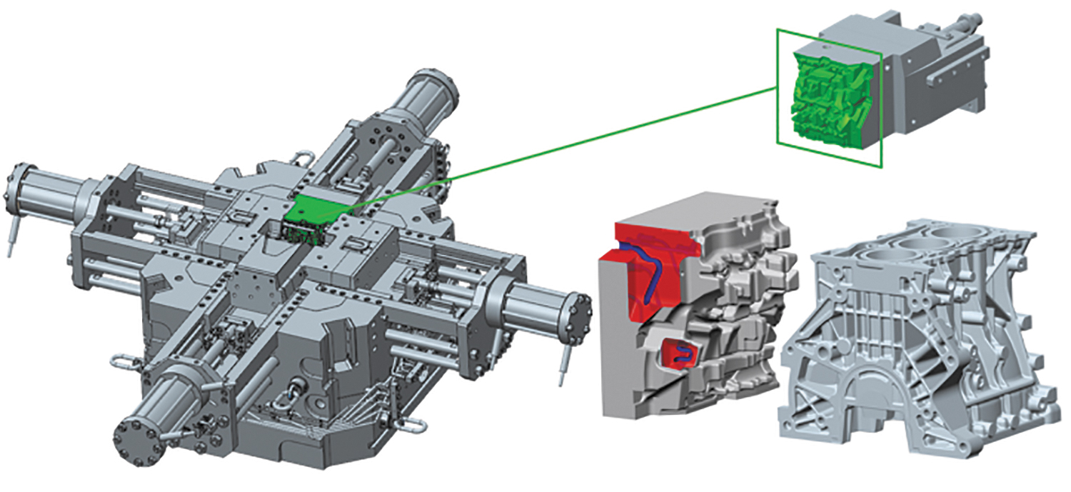
The part selected for the experiment is the upper slider to produce a 1.0 TSI three-cylinder engine block from AlSi9Cu3 (Fe). As shown in Figure 1, the slider forms 1/6 of the mold and formally forms the entire side of the final engine block casting. From a design point of view, it is a complex part with a shape, which contains large protrusions and deep pockets that recede into the tool's shape.
Basic information about the upper slider of the die with its position and the model of the casting.
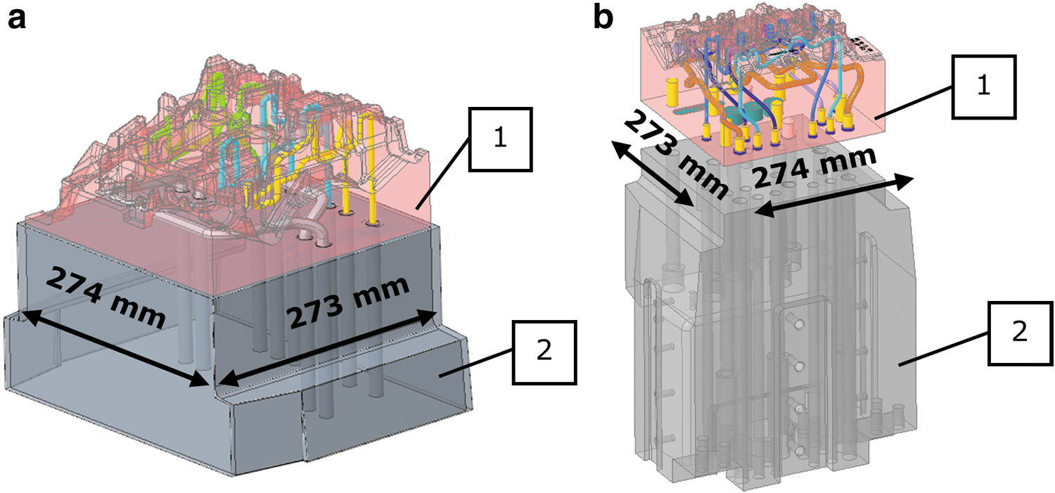
The first proposed variant was produced as a hybrid construction (shown in Fig. 2a). However, this variant was not implemented as the authors did not find an acceptable price range for a semifinished product made of material 1.2709 in the dimensions of ∼286 × 287 × 175 mm. Therefore, the authors decided to take the more sophisticated approach and implement the second design variant (shown in Fig. 2b). This variant was more complex in that the design of the slider and the guide had to be reworked. The slider was modified and designed so that it could be printed as one piece.
Compared with the original variant, the cooling system was completely redesigned, where, instead of the initially straight drilled channels, a conformal cooling system was created. The guide had to be adjusted to attach the printed and machined slider. For this purpose, the guide was considerably enlarged and completely made by machining. The final step was to connect the two parts using screw connections, guides, and adjusting pins.
The initial variant of this part contained a conventionally made (drilled) cooling circuit. As shown in Figure 3, the circuit was made by drilling from the bottom and sides of the part. Subsequently, it was necessary to use plugs to connect these holes into one circuit. This, however, is one of the main disadvantages of plugs. On average, 10% of molds that return to the ŠKODA AUTO tool shop for repair are caused by fluid leaking through the plugs. Leakage of the cooling medium into the mold cavity is hazardous to the resulting casting quality, as it directly affects the occurrence of gas porosity and shrinkage. Given these concerns, in this variant, the production of conformal cooling can be considered safe since the aforementioned plugs are not needed.
Original and new slider concept and basic dimensions.
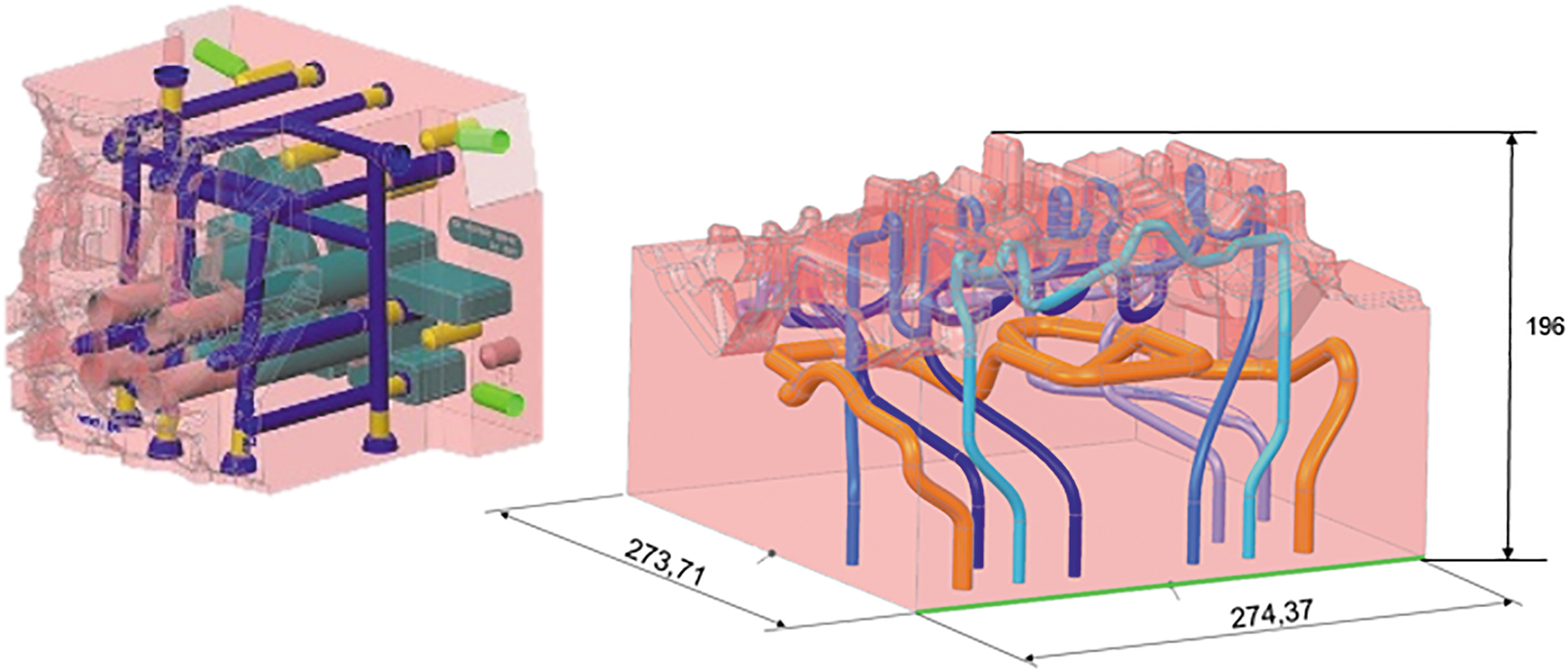
The newly designed conformal cooling can be seen in Figure 3. This cooling is divided into four separate circuits. Three of the circuits are designed to intervene directly in the shaped part and are responsible for the uniform cooling of this part of the tool. The geometry of the channels was chosen based on what is possible with printing technology and the dimensions of the shaped protrusions on the mold. A circular cross section with a diameter of 6 mm is printable without major deformations and changes in the size or shape of the channel.20,33 The last branch (orange in Fig. 3) is designed to be much more massive and was placed there for temperature equalization, similar to a tempering channel.
For these purposes, a special cross section was dimensioned, which should be self-supporting and therefore not require supports, as these structures would not be able to get out of the product. The base of the shape is a circular cross section with a diameter of 10 mm, which is then transformed into a teardrop shape. If a circular cross section with this diameter were left, the shape and size of this channel would be degraded.
As for machining allowances, these were selected based on colleagues' previous experience from AUDI AG. It was impossible to follow any recommendations here, as the part was huge, and no recommendations were found. The only source 12 in this work based on the initial failure is the use of 2% shrinkage compensation with which the tool was printed on a second attempt. The machining allowance was 2 mm on the part's shaped part and was used mainly for compensation and final machining. The sides and base, mainly due to the expectation of the large deformations due to the printing process itself, were provided with an addition of 6 mm. This allowance was determined with a large margin because, in the event of a fatal deformation of the part, this part would not be usable and would have to be produced entirely again.
Printing of the slider (material, printer, parameters)
The material used in this study and composition are shown in Table 1 (the powder lot has been verified by the EOS powder Inspection Certificate according to EN 10204, type 3.1 for AUDI AG). Chemistry analysis has been done in an external ISO 17025-accredited laboratory. The powder for the experiment used was 1.2709 from EOS GmbH (EOS GmbH—Electro Optical Systems, Krailling, Germany). The chemical compositions differ slightly from lot to lot. This experiment used only powder from one manufacturing lot produced under a gas atomized atmosphere and delivered in 10 kg packages. Around 400 kg of powder was used to fill up the powder tank at the machine. This steel is characterized by excellent strength with high toughness and excellent mechanical properties, the heat treatment options of which can easily be achieved after the printing process. 34
The Chemical Composition of the 1.2709 Powder
The slider was produced on an EOS M400-1 machine equipped with a 1000 W laser and a build chamber size of 400 × 400 mm × 400 mm. The chosen atmosphere in the building process was filled with nitrogen instead of argon. EOS performed a basic analysis of the powder, the particle size distribution in the manufacturing lot was tested in AUDI AG with the result being as follows: d10 was 21 μm, d50 was 35 μm, and d90 was 53 μm, and the fraction retained of >63 μm was 0 determined by a sieving test. For comparison, another powder manufacturer states a generic particle size distribution in the range of 20–65 μm. 35 A scanning electron microscope (SEM), Tescan Vega 3 LMU (TESCAN, Brno, Czech Republic) with accelerating voltage 20 kV, detector secondary electrons + backscattered electrons, was used for another powder analysis.
Figure 4a shows the powder material by an SEM. The state of the powder did not differ in any special way from the standard state. Compared with EOS, 35 at first glance, it showed slightly more irregular and deformed particles.
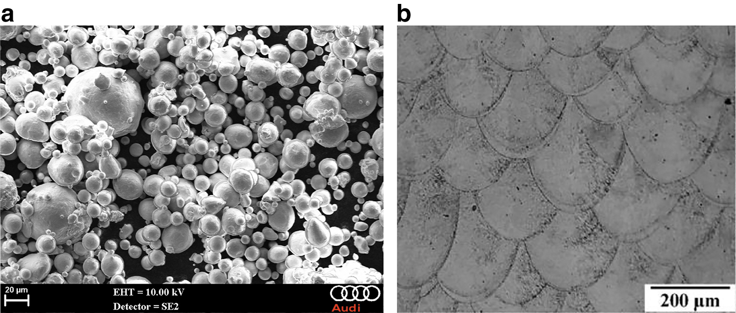
The part was printed with parameters, as in Table 2, with 99.8% relative density after printing (Fig. 4b). The powder characteristics, laser power, layer thickness, and the material itself have a huge impact on the process. 36 The behavior of the material and the optimization of the parameters for every material are necessary, which the authors examined and verified in the study. 37 Therefore, AUDI AG has developed its parameters with 37% reduced printing time than the standard parameter. Applicators can choose between different standard exposure patterns. Choosing these patterns greatly influences machining time, part quality, density, and distortions. 38 The exposure pattern “stripes” was used for this slider because of the gained experience in programming and printing such a vast tool insert.
Printing Parameters for the 1.2709 Powder (Skin Core) from AUDI AG
The main aspect of the decision was to reduce the printing time and avoid the risk of job crashes due to the reduced printing time. It even allows also cooling channels with 20° down-facing surfaces to be built without support structures. The production time of the part was 381 h. Figure 5 shows the already finished printed slider with conformal cooling.
Heat treatment
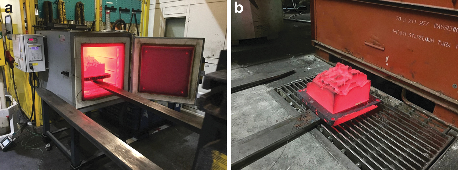
The heat treatment was performed based on the requirement for the application in the real casting process. Two different chamber circulation furnaces were used generally at AUDI AG, Padelttherm HDE 600/1200 (Padelttherm GmbH, Markranstädt, Germany) and Nabertherm N 120/85HA (Nabertherm GmbH, Lilienthal, Germany), for the heat treatment of the tool inserts. The Almemo Datalogger and Sensorsystem (Ahlborn Mess- und Regelungstechnik GmbH, Holzkirchen, Germany) were used to control and log the temperature curve in a central region of the insert and a cooling channel. Based on the authors' experience and the recommendations from the manufacturer, a final hardness in the range of 48–51 HRC was required. After printing, the part was annealed at 850°C for 1 h to reduce residual stress, with the part remaining on the build platform during this process.
Following this came the hardening procedure to reach the required hardness. The part was heated at a rate of 100°C/h to a temperature of 465°C, where the heat preserving of 10 h was performed at this temperature. Then the part was removed from the furnace for the cooling down outside in normal air (Fig. 6).
Finishing operations and deployment of the slider in serial production
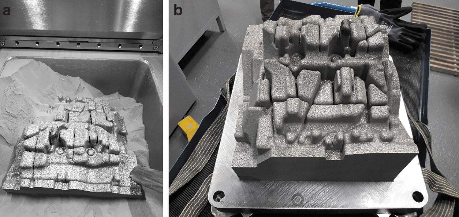
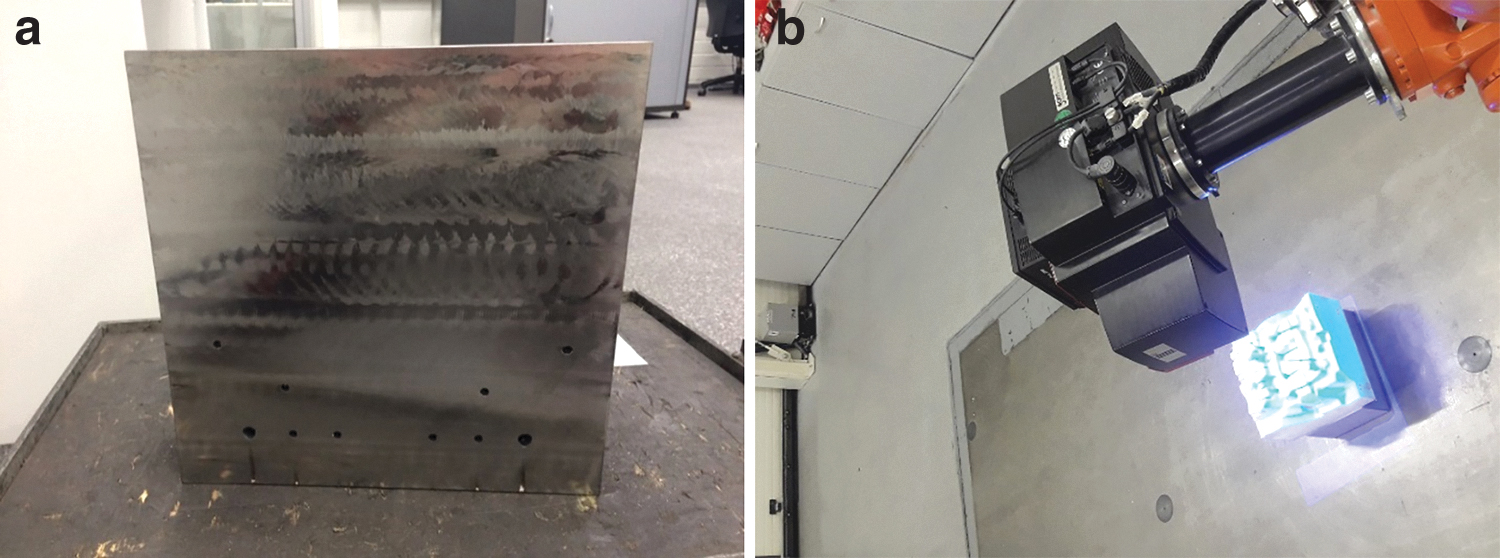
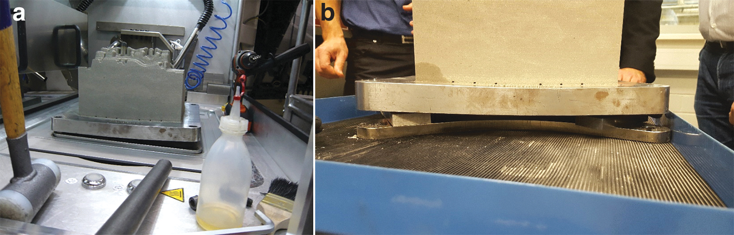
After the heat-treatment process, it was necessary to separate the slider from the build platform on which the part was printed. Due to the size of the part and the actual stresses in the material, it was decided to sacrifice the build platform and mill this excess material. This decision is shown in Figure 7a. The printed part was then measured (Fig. 7b) using an ATOS Compact Scan 2M optical scanner and GOM Inspect software from GOM (GOM GmbH, Braunschweig, Germany) to verify machining allowances and to detect any deformations (deviations) that may have been caused by the 3D printing process itself or the subsequent heat treatment.
These allowances were added earlier in the preparatory phase of the project, namely 2 mm on the shaped part and 6 mm on the sides of the part to compensate for possible deformations during production. The alignment of the part was performed by the “best-fit” method on the part's shaped part.
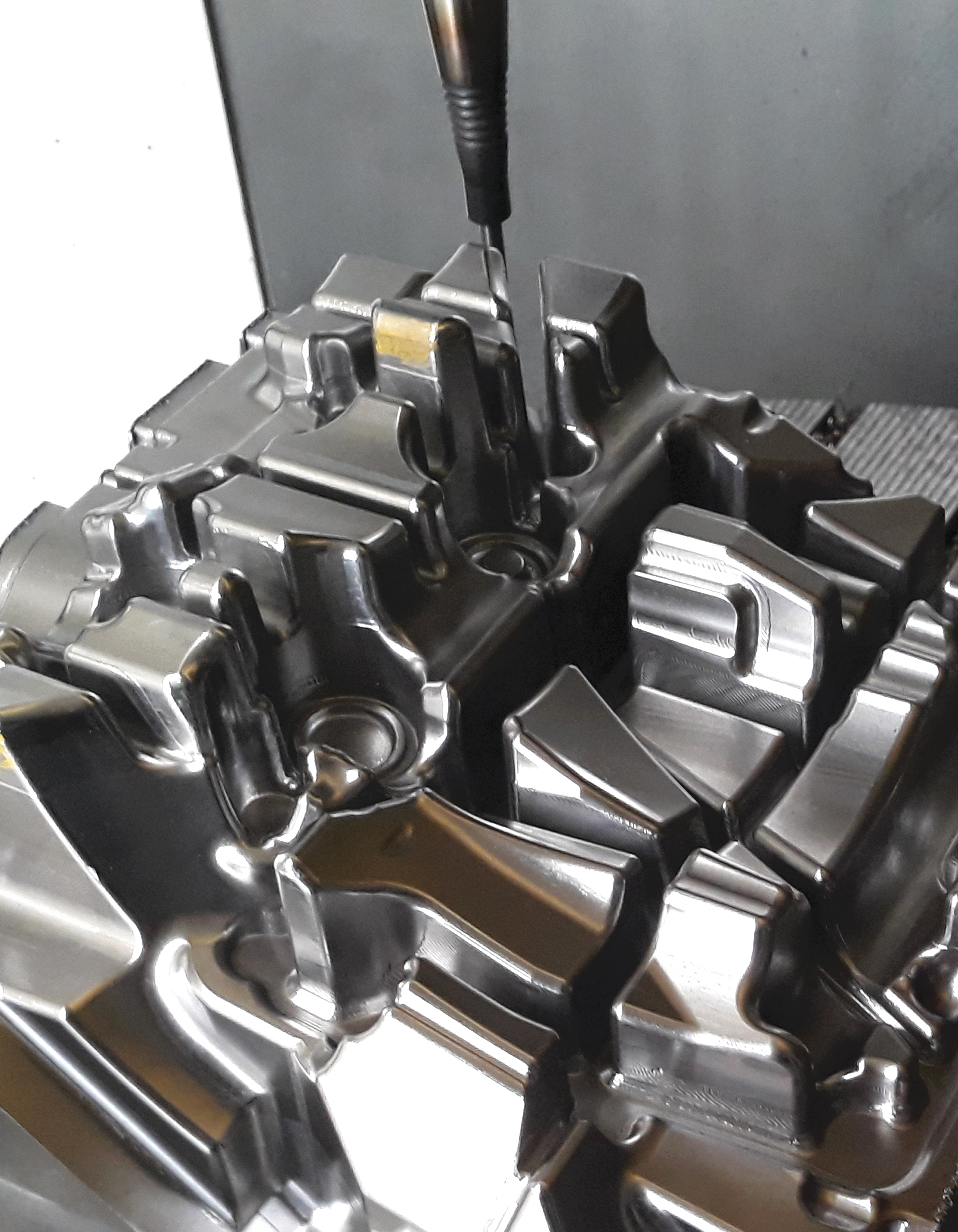
The final machining was performed on a DMU 125 P duoBLOCK from the manufacturer DMG Mori (DMG Mori Seiki Co., Ltd., Nakamura-ku, Japan) when it was necessary to machine the entire shaped part of the tool (Fig. 8a). For these machining purposes, a unique positioning jig was made on which this part was subsequently seated and used the DMU 125 P duoBLOCK workbench that was clamped. As shown in Figure 8b, the shaped part of the tool is very indented, and so, smaller tools with a large extension were used for the machining.
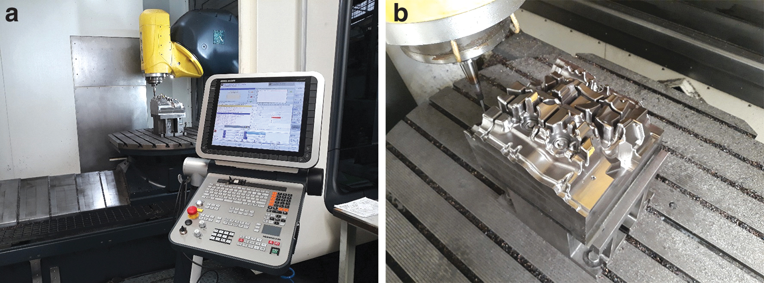
The entire mold was transported to the ŠKODA AUTO foundry, where it was clamped on an IDRA OL-2000 die press machine (IDRA S.r.l., Travagliato, Italy). The mold placed on the casting machine with the 3D-printed slider is shown in Figure 9a. Figure 9b shows the detail on a 3D-printed slider just before the die casting process itself. Due to the need to analyze and compare the simulation temperature fields versus the actual state, instrument temperature measuring devices were used during casting.
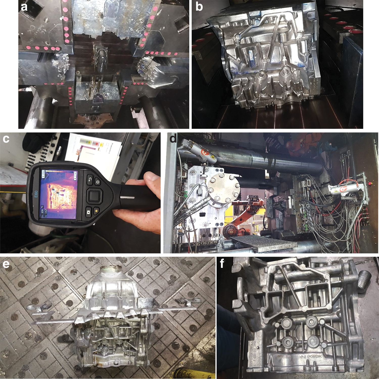
An FLIR E60 thermal imager with a temperature range up to 650°C, a temperature sensitivity of >0.05°C, and a measurement accuracy of ±2°C was used for operational imaging (Fig. 9c). The images obtained from this thermal imager were evaluated in the software FLIR Tools ver. 4.1.14066.1001 (FLIR Systems, Inc., Wilsonville, OR). Stationary thermal cameras were installed and used to perform a more thorough and accurate analysis of the temperature fields, shown in Figure 9d.
Before the mold can be approved for full-series production, the mold must complete a sampling cycle and produce 50 pieces for initial verification of the quality of the castings. This is followed by serial operations, and before the mold produces the first 5000 pieces, it is more closely monitored. Figure 9e shows a casting with all technological parts (inlet system, mold venting), which, after being removed from the mold, is transported to a cooling bath to stabilize the mechanical properties of the casting. Figure 9f shows the final casting after finishing, if all technological segments are gradually removed from the castings and the part is prepared for further processing. At the same time, Figure 9f shows the casting side created by the 3D-printed slider. During the visual evaluation, it was stated that the quality of the parts complied with ŠKODA AUTO's internal regulations.
Methodology for evaluating repairs in the tool shop and foundry
The methodologies described below are used for the statistical evaluation of repairs in the ŠKODA AUTO departments. It is important to mention that three other variants (36th, 37th, and 38th) of the same mold were selected for evaluation and comparison, where this same slider was made conventionally. These mold designs were chosen mainly because they were put into serial production at approximately the same time, and the number of castings on each mold was approximately the same as for the mold with a 3D-printed slider.
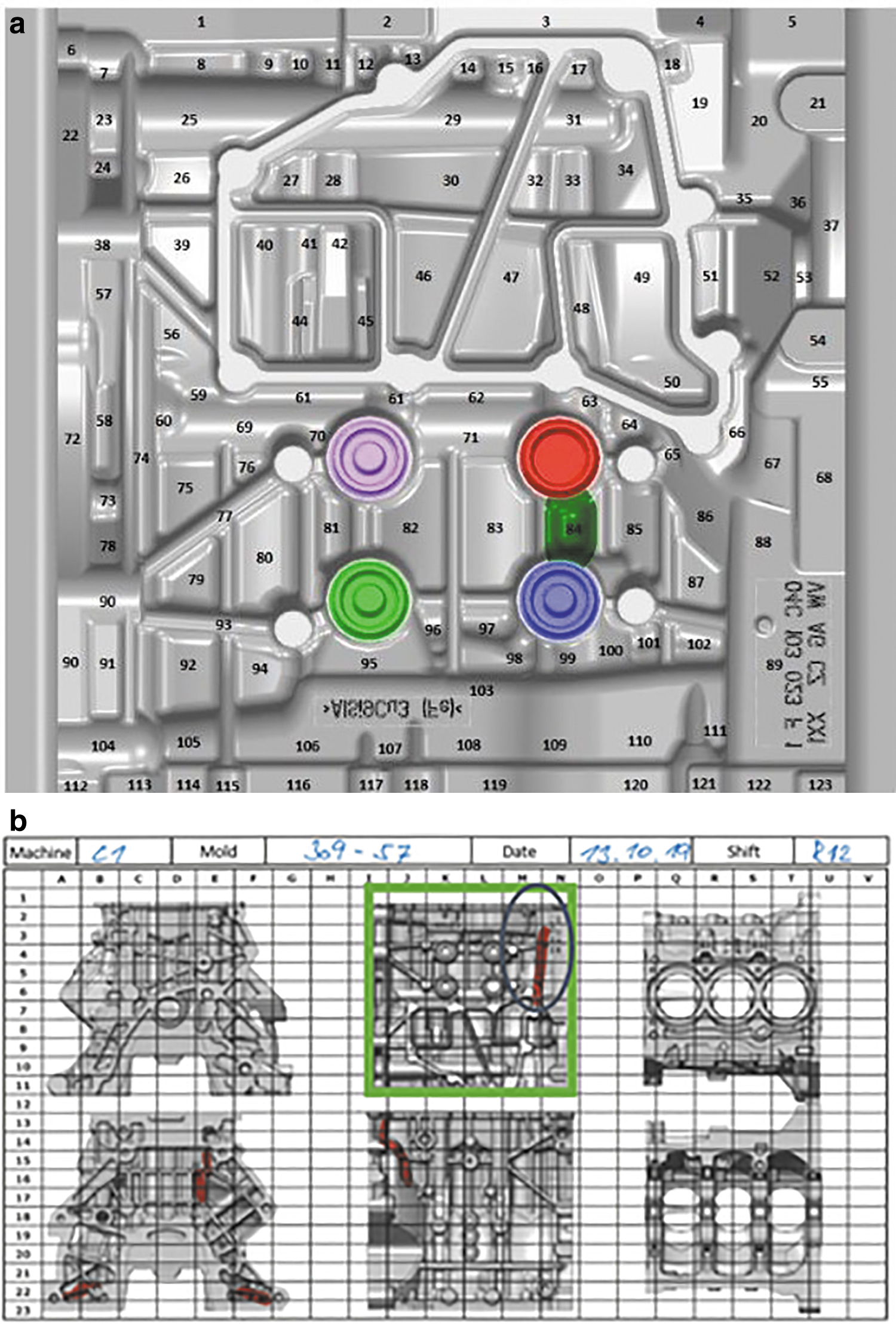
After taking over the mold, it is disassembled into individual parts in the tool shop according to the type of damage and the need for intervention. After disassembly, the upper slider is analyzed based on the application “service sheet,” where an employee records all repairs. As shown in Figure 10a, this part is divided into areas for better orientation and statistical evaluation of repairs. The area of repairs and the method (grinding, welding + machining, replacement of cores) are then entered into the application as mentioned above.
Repairs carried out on the slider
In the foundry department, repairs are recorded, performed directly on the casting machine in a serial production. The course of this repair is recorded in the checklist, which is shown in Figure 10b. Repairs in the foundry are operative, and mainly involve grinding soldered aluminum off the tools. An intervention of a similar type is then marked in red in the tool diagram in the checklist, as shown in Figure 10b.
These data (both from the service sheet and the checklist) will then be used for statistical evaluation of repairs and indicative quantification of costs for these repairs.
Results
Temperature field and heat dissipation (simulation vs. reality)
The motivation for this solution was the uneven cooling of the existing cooling solution produced by drilling. Due to this, the protrusion on the shaped part of the slider overheated, and the surface of the casting was damaged. This phenomenon can be seen in Figure 11 from the simulations of the temperature conditions of the “mold-casting” system in the ProCAST SW. Conformal cooling has resulted in much higher internal cooling efficiencies. Heat dissipation by a large cooling surface near the shape ensures an even temperature field of the mold and shortens the setting time of the casting. However, it was not possible to verify the full cooling potential of the 3D-printed slider during the test, as the rest of the mold had to be set to conventional process parameters.
Comparison of cooling methods (conventional vs. conformal) based on simulations in SW ProCAST.
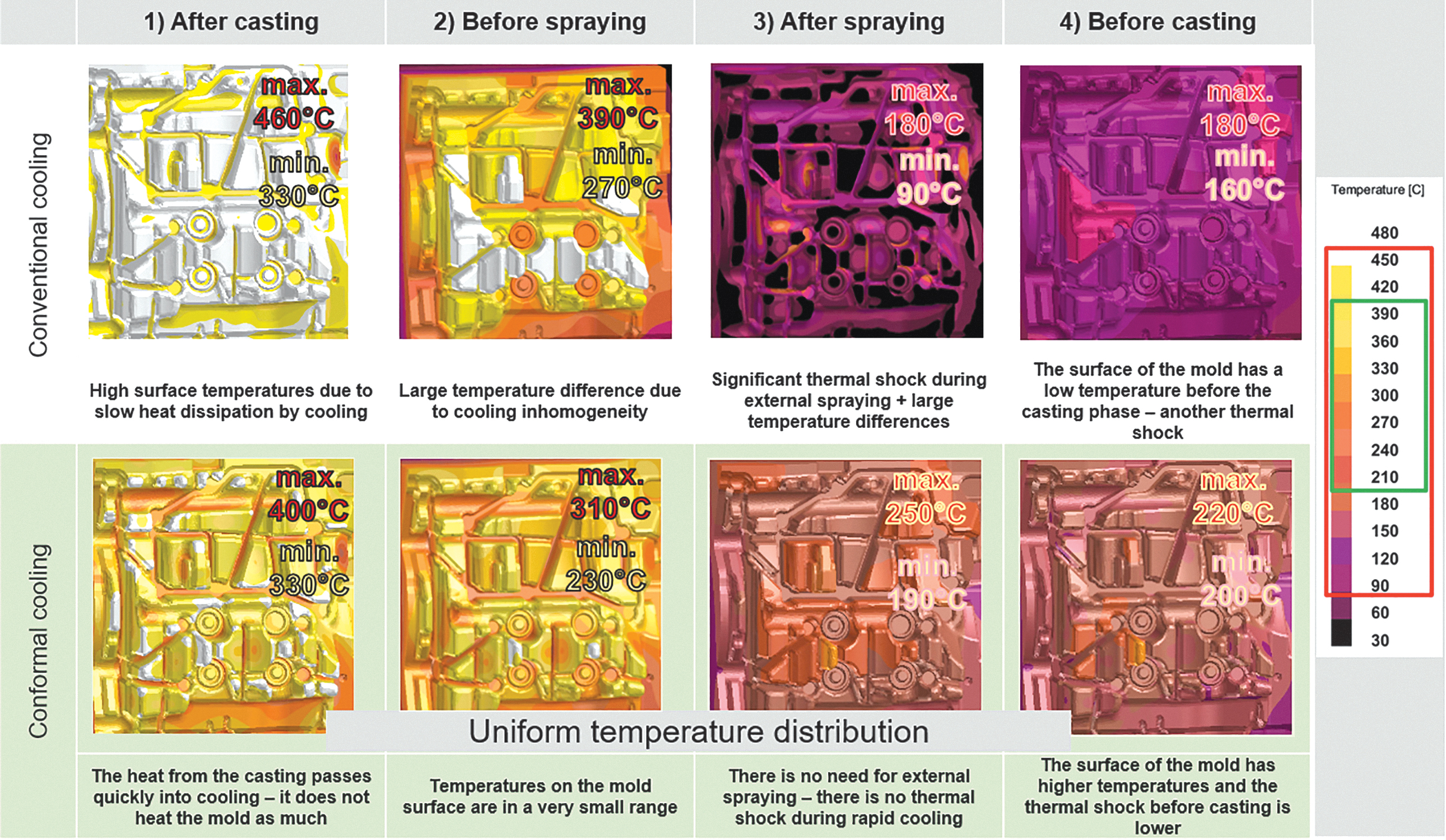
Significant differences can be observed, shown in Figure 12, using conventional or additive technology. During the conventional cooling method, high temperatures are reached on the surface of the mold in the after-casting phase, and conversely low temperatures after spraying. The temperature range here is up to 370°C within a casting cycle of ∼130 s. The temperature field of the 3D-printed slider during the casting cycle does not reach such significant extremes, and therefore, the part operates in the temperature range of ∼210°C. Compared with the existing technology, this is a significantly more suitable course for the tool life and the quality of the casting. This is demonstrated in Figure 12 by actual measurements.
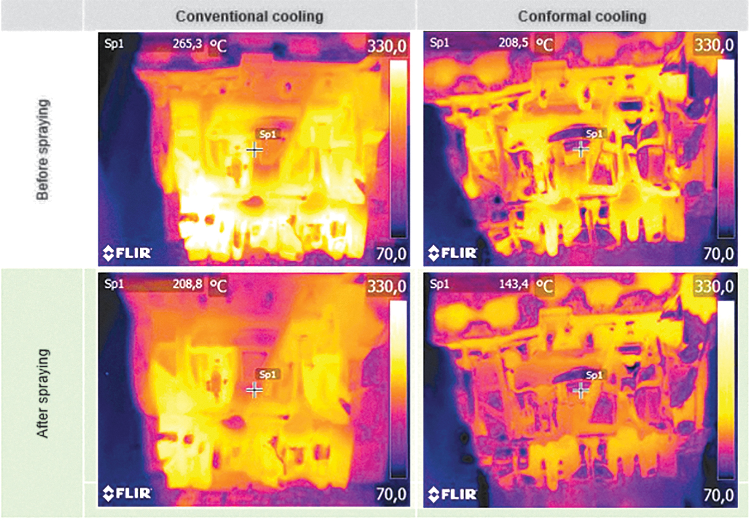
Comparison of cooling methods (conventional vs. conformal) based on thermal imaging measurements.
Despite the considerably limited performance, a significant improvement was achieved in the simulation compared with the conventional variant. The surface temperatures of the mold are kept in a much smaller range (conformal cooling 210–390°C vs. conventional cooling 90–450°C) during the casting cycle, the shape itself is also more uniform in temperature, and the solidification of the casting has been shortened by 5 s in the area around the upper slider (Fig. 13a vs. Fig. 13b).
When using conventional cooling, it can be stated that the tool is superheated before spraying and then rapidly cooled to subcooled in places, which has a significant impact on reducing tool life. Conversely, using conformal cooling, it can be argued that lower temperatures are achieved on a given tool, and none of the protrusions is dramatically overheated.
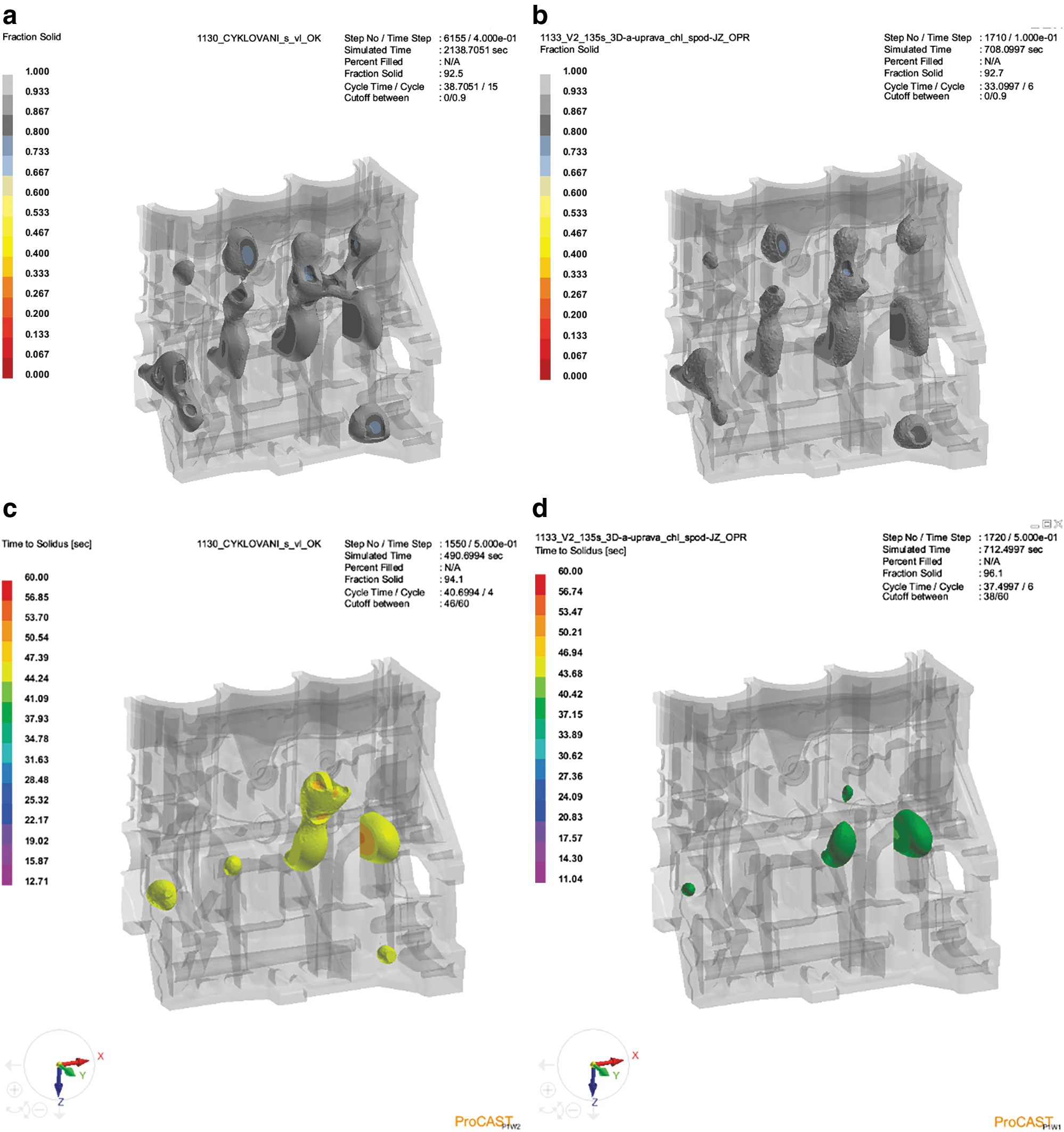
Another result in favor of conformal cooling is the analysis of the simulation of the solidification of the casting (Fig. 13c, d). From the simulation result, the slider with drilled cooling contains largely risky places where a defect could form (Fig. 13c). In contrast, specially designed conformal cooling produced by AM will ensure that the solidification of the casting is faster and far more sophisticated. Therefore, it can be seen in Figure 13d that a casting made with a conformal cooling tool contains fewer risk areas where a defect could occur.
Faster and more even solidification of the casting results in a lower risk of volume shrinkage. The engine block casting is characterized by great complexity in shape and a significant variety of wall thicknesses (5–20 mm). Conformal cooling throughout the slider allows heat to be removed from the casting more evenly. The solidification of thick-walled parts is thus faster and partially approaches areas with a thin wall. The number of risk areas has thus been significantly reduced (Fig. 13d).
Evaluation of case study
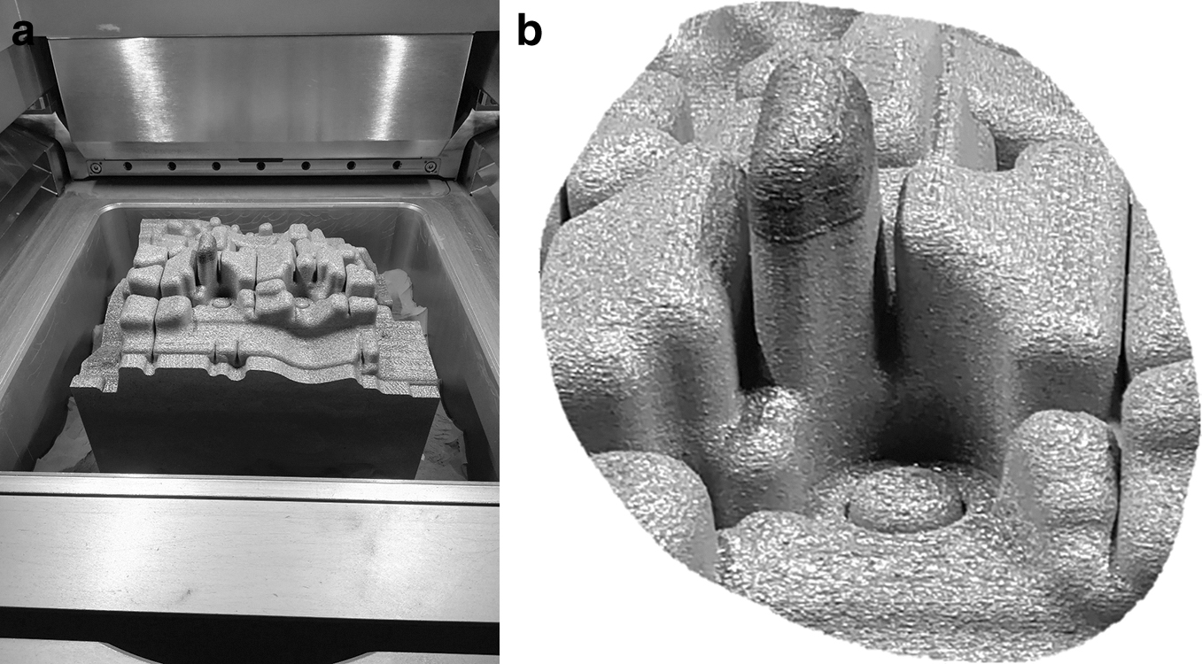
The production of a part of these dimensions alone has already brought many interesting and factual findings. Because printing this job took ∼16 days, several complications could be expected within the printing itself. The printer manufacturer warrants that the used printer can be in continuous operation for 9 days. If the job is longer, it has to be continued at its own risk and without any guarantees. The first complication that occurred in this case was the interruption of the job near the end of the whole part. The defect caused by the interruption of the job and the subsequent resumption of the printing process is shown in Figure 14a and b. Because a few minutes elapsed during the interruption of the printing process and the continuation, it is assumed that this defect would not cause a significant part problem.
In addition, it must be taken into account that after printing, the part was heat-treated and finally machined. Due to the use of the part in serial production, it was not possible to perform a deeper analysis. However, based on previous experience, different mechanical properties can be expected in a given area, which should be homogenized due to the heat treatment used.
Another complication, which was caused mainly by the size of the printed part, was the influence of residual stresses, which resulted from the principle of the production process of components by the L-PBF method. Because the component is manufactured layer by layer, there is constant sintering using a laser, and thus, heat and stress are input into the manufactured component. This defect caused problems already in the phase of removing the part from the build chamber.
Due to the distortion of the build platform (shown in Fig. 15a, b), it was not possible to remove the part from the printer, and it was necessary to partially drill the screws. This caused partial damage to the machine's working cylinder, and it was necessary to repair the equipment after this job. This must be considered when printing a larger part because there is often no other option to remove the part in the case of deformation of the build platform in the build chamber.
Distortion of the build platform due to residual stress
Figure 16 shows the measurement protocol immediately after printing (before heat treatment and other operations). This protocol was created by comparing STL models, the one used for printing, and the scanned part. Due to the size of the part, deviations can be considered acceptable, as the part's usability has not been compromised. Due to the lack of research in this area mentioned in Ref., 12 the authors decided to use larger allowances to cover these deviations. The largest deviation was recorded in the shape part of the slider and was 0.485 mm.
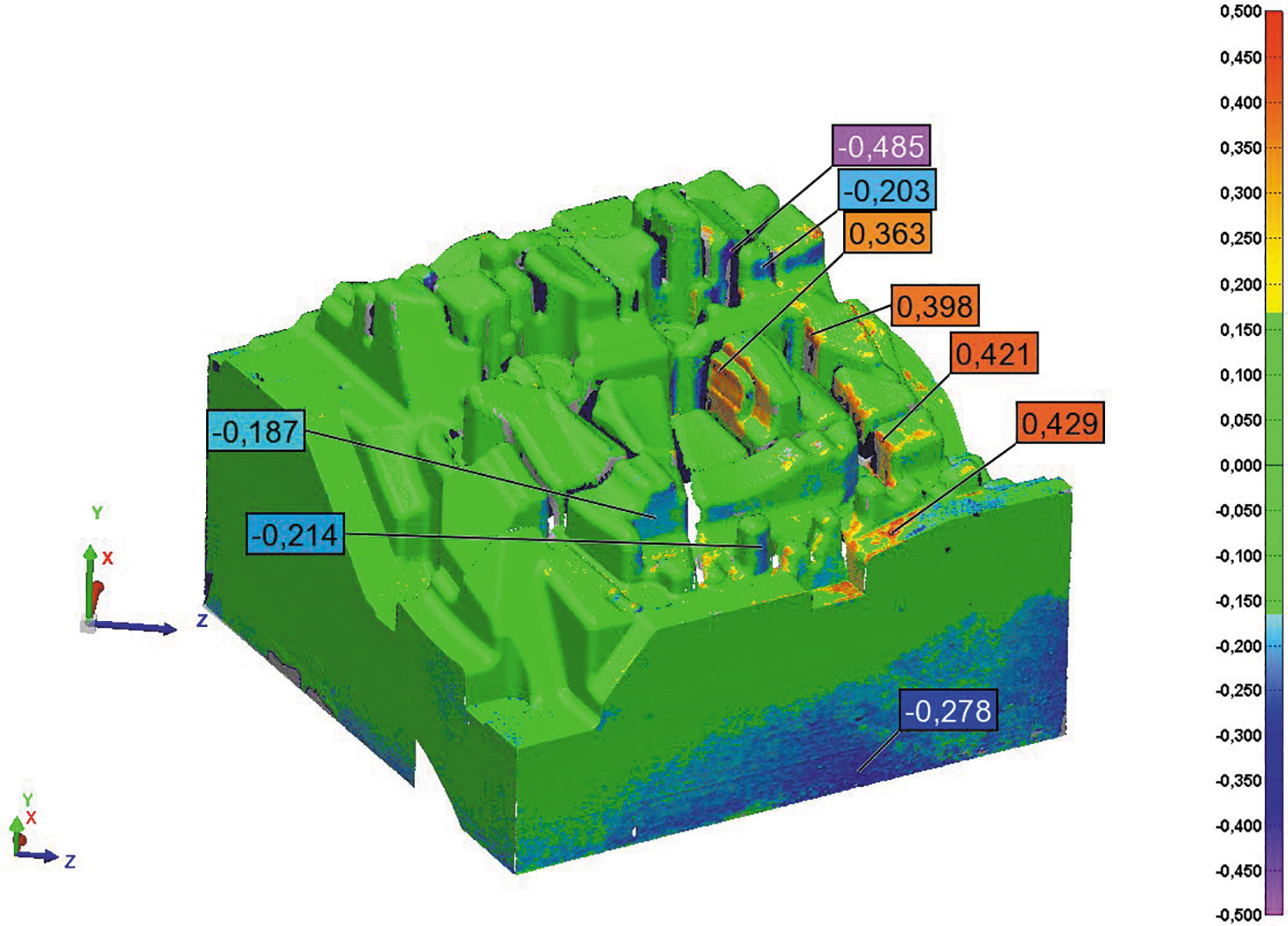
Detail from the measurement protocol after printing.
The printed tool was also measured as described in the previous chapter, mainly to verify machining allowances and to detect deviations (deformations) caused by the manufacturing process and heat treatment. To create the report, the STL model of the printed part was compared with the CAD model of the final slider. As demonstrated in the measurement protocol (Fig. 17), the actual dimensions of the shaped part are in the range of 1.5–2.3 mm (nominal dimension 2 mm), and the sides are in the range of 5.5–6.2 mm (nominal size 6 mm).
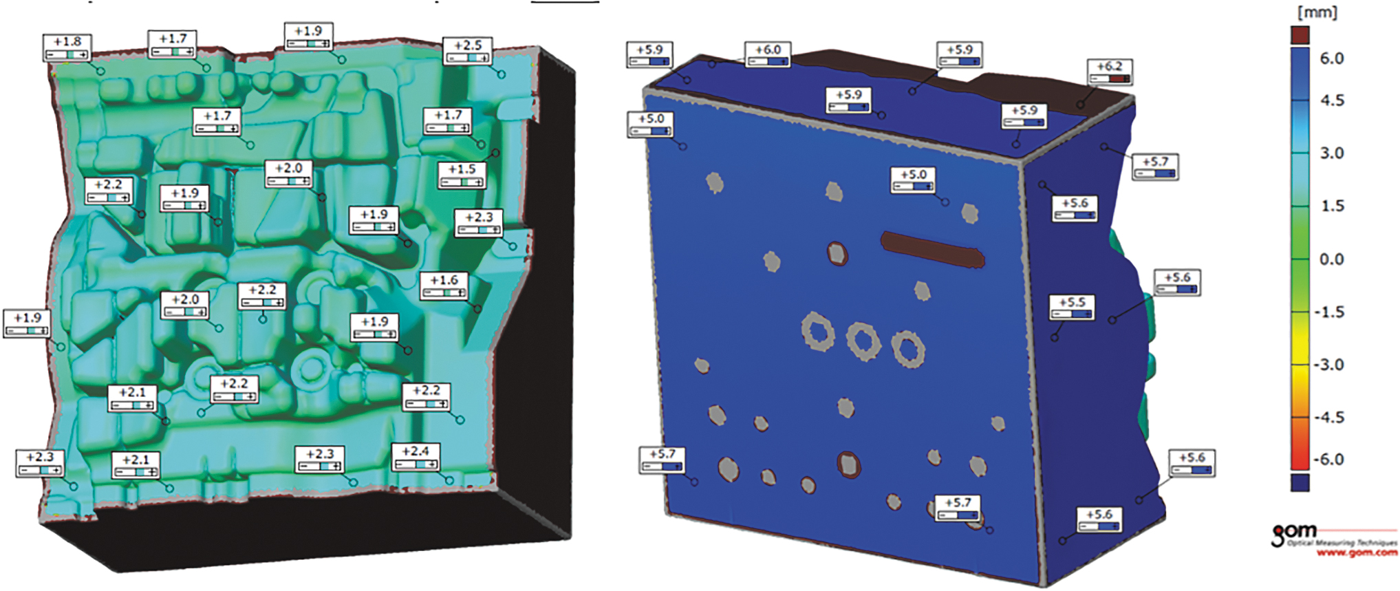
Detail from the measurement protocol after heat treatment (shaped part vs. sides and base).
This fact also confirms that the printing of such a large volume of material is quite unpredictable for the current generation of machines, and it is necessary to allow for deformations introduced by the production process itself. Authors agree that they would have more insight if the build was simulated beforehand to be compensated. This could be a further continuation of the research.
Inspection of manufactured castings
Visual inspection of the castings took place after the production of 5000 pieces, and the result is shown in Figure 17. At first glance, no major differences were noted, except for the detailed parts of the castings, shown in detail in Figure 18. At first glance, local ribs, shapes, and radii were far more detailed in the case of a 3D-printed slider (Fig. 18b). The result can be attributed to the use of conformal cooling, which better and more evenly removes heat from the tool (similar to the study by Jarfors et al). 13 Therefore, the tool wears less and tolerates cyclic thermal effects better. 8
Visual inspection of castings after the production of 5000 pieces
Metallographic analysis was used to evaluate the effect of a printed tool with conformal cooling on the casting quality. Samples for this analysis had to be prepared from areas of castings where the benefit of more intensive cooling was applied. These areas were analyzed and selected based on evaluation in SW ProCAST. The selected areas had the largest differences in solidification speed, and therefore, it was necessary to check whether there was a significant difference in grain size in the area resulting from cooling. These locations are shown in Figure 19. The casting quality was examined at problem areas of various depths from the surface of the part.
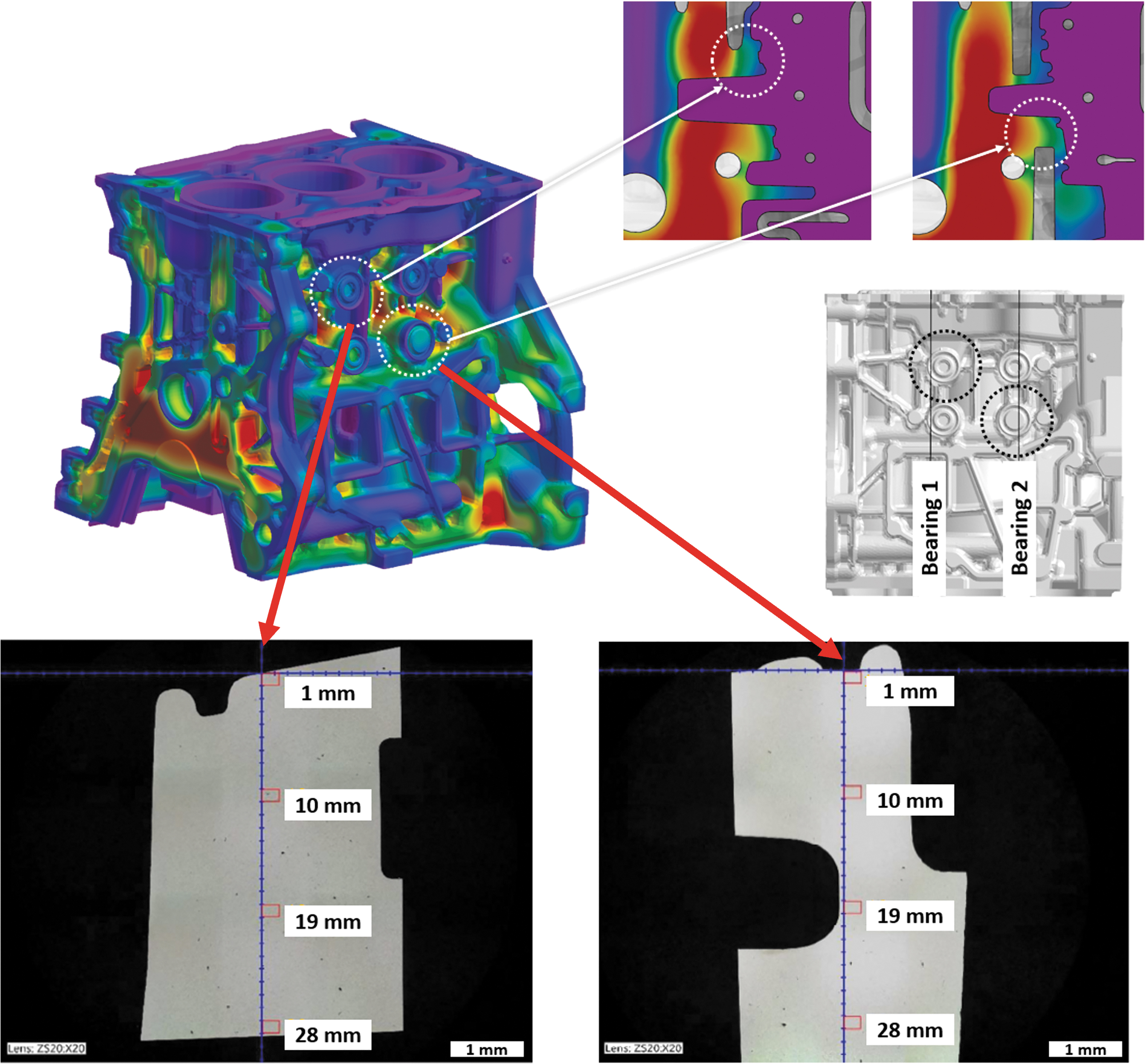
Selection of problem areas for examination by metallographic analysis.
Figure 20 shows the results of the metallographic analysis. Depending on the distance from the surface, samples from castings made with a conventional and 3D-printed slider were compared. The largest affected area is close to the surface, as this part directly affects conformal cooling. Figure 20 shows areas 1 and 2 mm deep from the surface. Looking at the character and size of the grains, it can be stated that a casting made with the 3D-printed slider has more refined grains in the surface area due to more intensive cooling. Furthermore, this effect is lost in-depth, and the grain size is the same for both the conventional slider and the 3D-printed one.
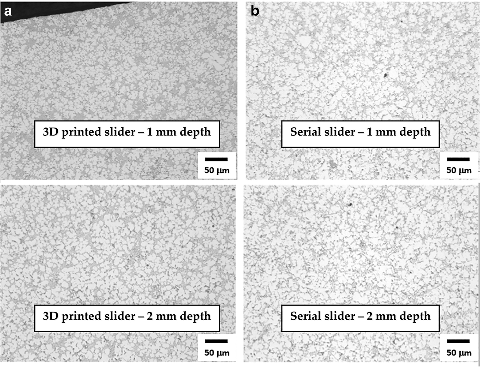
Images of metallographic sections
Evaluation of repairs
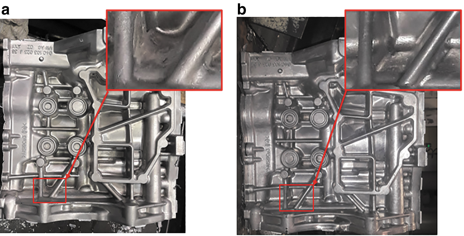
The efficiency of conformal cooling mentioned in the publications7–11,13–15,17,18,22,28 can also be seen when soldering aluminum to the tool itself. Figure 21 shows sliders from the same mold after casting a certain number of pieces, where the only difference is in the cooling method. Figure 21a represents a slider with conventional cooling, and in contrast to the variant with conformal cooling, Figure 21b, it is evident that there is a more pronounced sticking of aluminum on the superheated parts. In contrast, less soldering can be seen on the 3D-printed tool. This effect is mainly caused by conformal cooling, resulting in a more stable thermal field. This effect has significantly contributed to the fact that the repair/maintenance of the 3D-printed slider is faster, as it is not necessary to remove such soldered aluminum in a complicated and time-consuming manner.
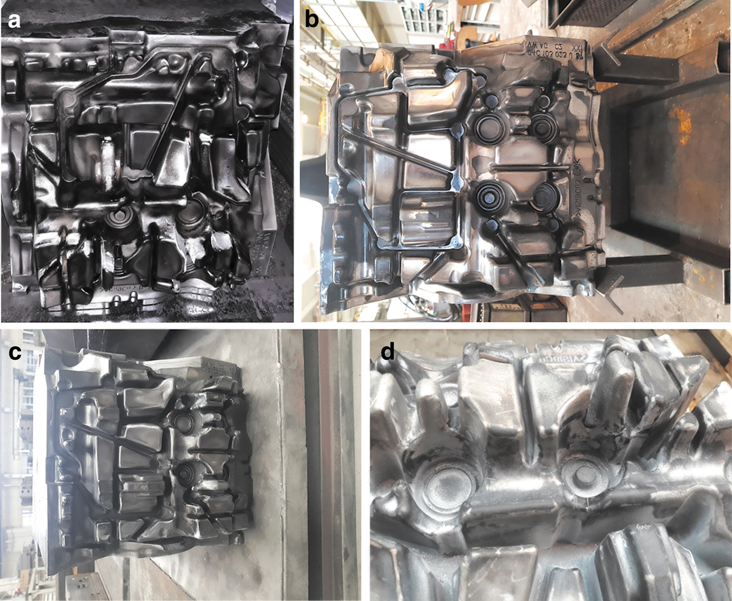
Soldering of aluminum to the slider
Figure 21c and d represents an analogous comparison after 40,000 pieces, or approximately half of the tool life of the mold. When the critical parts of a given tool are highlighted after producing the same number of pieces, the serially designed tool suffers much more from the sticking of aluminum and the formation of cracks in the thin ribs.
Tools for HPDC suffer for the most part from aluminum soldering. 4 Such layers of aluminum need to be removed regularly during the casting process so that each mold lasts in the operation of the foundry for as long as possible per application and produces quality castings. The total number of repairs is shown in Table 3.
Summary of Repairs in the Foundry
3D, three dimensional.
Apart from the maintenance in the foundry, it is also necessary for larger scale maintenance. Most often, this refers to crack repairs, broken shapes, and replacing the removable cores. These repairs are already being carried out in the ŠKODA AUTO tool shop. The most significant advantage in the case of a 3D-printed slider is the cores, which are part of the tool and are not replaceable. This step was possible by replacing the cooled replaceable cores with a conformal cooling circuit produced by 3D printing. In general, conformal cooling, as in the studies,7–11,13–15,17,18,22,28 contributed to the increased functionality of the whole tool, which is substantiated in Table 4. When comparing the same mold in different variants with approximately the same number of castings, a considerable saving (reduction to 35%) of the number of total repairs is seen. It can be read from Table 4 that only half of the tool life (∼40,000 castings) was repaired in only six shapes, and, unlike all conventional variants, the cores did not have to be changed.
Summary of Repairs in the Tool Shop
Comparison of production costs
Another very beneficial conclusion is the recapitulation of the production costs of the part. Cost can often be a sensitive topic, and with 3D printing technology, this is even more so the case. As mentioned in studies,4,5 powder bed technologies are very inefficient relative to other technologies, for example, DED, which also contributes to them being very costly. This fact must be stated in the case of this study. Table 5 compares the production operations of the same slider in the series versus 3D printing versions. It can be stated at the outset that there has been some simplification, and the beginning is taken only after the semifinished product (in the case of a series—steel block, in the case of 3D printing slider with machining allowances and after heat treatment) is located in the tool shop. After that, the necessary steps have already been taken on each tool.
Overall Comparison of Production Time and Production Costs
At first glance, it can be seen from the summary, Table 5, that the difference in total costs is marginal (∼60% higher costs). The production time in the variant considered in this way (if the beginning is only after the semifinished product is delivered) is more favorable for the 3D-printed variant, and the total production time is ∼64% lower than the serial part. From the authors' point of view, the machining time was too long, and there are alternatives with the potential for lessening this. There could be a space in the future to try the idea of Oter et al 21 when no postprocessing was applied to the printed part. Significant financial savings would also be made if this idea were applied.
Of course, the actual deformations that arise as a result of the process itself cannot be neglected, and so, it is possible to reach the same conclusion as Stolt and Jarfors 12 when it was necessary to discard the part without the application of allowances and print a new one using shrinkage compensation +2%. However, with the current surge of interest in 3D metal printing, the authors remain optimistic that further price reductions can be achieved to the extent that 3D metal printing incorporating conformal cooling becomes price competitive with standard production methods.
Discussion
This article investigates the issue of production and uses in serial production of a large 3D-printed tool with conformal cooling for HPDC. Using this case study, the authors presented the production process of a unique tool in terms of dimensions and production method after evaluating the use of this tool in the serial production environment of ŠKODA AUTO.
First, an extensive state-of-the-art part was carried out, which served as a starting point for the issue. The research part was focused primarily on the field of molds and tools,1,2,4,7–12,15–30 the use of conformal cooling,7–11,13–18,20,22,24,25,28,30 and the field of simulations9–11,14,16,17,22,24,25 using additive technologies. The main conclusion drawn from this part is that the production of such a large tool (∼270 × 270 × 200 mm) by the method of metal 3D printing has not yet been realized, or the results have not been published. In this study, the authors agree with Stolt and Jarfors 12 that few publications exist on this topic.
Despite, for example, the authors Asnafi 4 or Griffiths 6 stating that there are far larger printers for metallic 3D printing, the largest tools found in existing publications were ⌀ 110 × 50 mm in the study by Piekło and Garbacz-Klempka 11 or 240 × 64 × 35 mm in the study by Stolt and Jarfors. 12 Therefore, it was decided to publish the results of this case study, which could demonstrate and transfer experience in the production of large parts using additive technologies.
In the design phase, it was necessary to decide on the optimal pathway to design the printed part. It was ultimately decided between two variants, where the first option was to print the part as a hybrid construction on a prefabricated semifinished block or modify a part of the existing tool and print the slider separately. Although a hybrid construction would appear to be a more suitable and simpler variant, it was not possible to implement it due to the absence of a semifinished block of the required dimensions ∼286 × 287 × 175 mm from material 1.2709. Therefore, a separate part was produced, and then assembled with a modified guide using screws and pins.
In this study, it is necessary to state that this step could significantly affect the total cost because, in the hybrid variant, the printed height would be 10–20% lower than in the implemented variant. Another significant modification, which was reflected in the total cost, was modifying the existing tools for assembling the printed slider.
Another important criterion for such large parts is the machining allowance. As correctly reported in the study by Stolt and Jarfors, 12 due to the few articles on this topic, it is impossible to determine the machining allowance precisely and with certainty. After the experience, 12 when the authors decided to produce a tool at nominal values, it was necessary to produce a new tool with 2% shrinkage compensation. This value was also used for the slider, where the addition on the sides and base was 6 mm due to the expected large deformations due to the printing process itself. A smaller addition of 2 mm was chosen on the shaped part mainly to compensate for the inaccuracy of the production technology and to final machining.
The result is reflected in chapter “Evaluation of case study” when, due to the production process, the final part was so deformed that it could not be removed from the printer itself. Using the additions mentioned above, it was guaranteed that even such a deformed part could be machined to the required dimensions without further complications and used in the production process. The authors are aware that with the help of simulation, the issue of compensation could be solved in the preparatory phase, and it could be the next step of the research. As for the manufacturing inaccuracy of such a large part, it is necessary to analyze two states. The first state is immediately after printing when the deformation of the part is prevented to a certain part by the build platform on which the part was printed.
In this study, the largest deviations were ±0.5 mm from the nominal dimension. After heat treatment and cutting the part from the build platform, the deviations in the shaped part and on the sides of the tool were ±0.5 mm, while up to 1 mm was missing at the base. This can be partly attributed to the production process, but this cannot be stated with 100% certainty, as this error could have been caused by misalignment during machining and could have occurred in this step.
The total costs for the comparison of series and 3D-printed sliders are given in Table 6. In this table, all evaluated factors described in the Methodology for Evaluating Repairs in the Tool Shop and Foundry section were reflected after producing ∼40,000 castings, which represents half of the tool life. It achieved better results in almost all the evaluated criteria of the 3D-printed slider, in particular, the need for repairs, which were significantly less in the tool shop and foundry departments.
Summary of Total Costs
Another consideration, based on the difference in actual production time, is an even more significant reduction in the time spent producing a 3D-printed slider. Although, currently, the production time from receiving the semifinished product is shorter by more than 60%, even this time can be reduced. In this way, the authors encounter the possibility of production to minimize the allowance for machining (similar to). 21 Again, this is a bit of a theoretical consideration so far, as presented by Stolt and Jarfors, 12 and so, it is not yet worthwhile for such large parts. An experiment to leave the dimensions at nominal values resulted in the printed tool being on the order of several mm smaller and not subsequently usable. 12 Therefore, it was decided to use 2% shrinkage compensation, and with that, the part was already successfully printed and tested in production.
In the case of this study, the additions were chosen with even greater certainty and were up to 6 mm on the sides of the slider. This partly led to the fact that the machining time was relatively long and could be significantly reduced in the future.
The topic of cooling the HPDC mold has an ever-increasing priority. In a given production technology, productivity requirements are escalating, and heat dissipation in an ever-shorter period is being solved. More than ever, engineers need to think about how to accomplish this difficult task. In the past, the widely used external treatment with a high proportion of cooling water harmed the casting and tool life quality. The problem is caused by residual moisture in the mold cavity and large temperature shocks on its surface. This spraying technology has declined for many years, and external lubrication treatments with minimal cooling effects are increasingly being used.
The heat balance of the production process thus changes, and the missing heat dissipation must be replaced by more efficient internal cooling and verified by simulation in SW ProCAST already in the preproduction stage, similarly to the studies.14,15,22,24,25 The cooling effect of the casting mold can be increased in several ways. One of them is to increase the amount of water as a cooling medium in the inner cooling channels. Furthermore, it is necessary to approach the cooling as close as possible to the surface and the largest possible cooling area. The usual standard is to drill many interconnected cylindrical holes in the mold, to place several probes, nozzles, or baffles. A large number of cooling segments increase the complexity of the mold design, and it is also necessary to consider the often-limited number of connection points on the casting machine when designing.
Due to the decrease in cooling capacity, interlocking the cooling circuits is not always a suitable solution. With conventional drilling, it is often not possible to cover the entire surface of the mold, which is very fragmented and dimensionally diverse, well enough. Different wall thicknesses are created between the cooling channel and the casting, making it challenging to design a suitable cooling arrangement. Thus, a progressive metal 3D printing technology is possible. As verified in this study, AM will make it possible to overcome the vast majority of the disadvantages mentioned earlier and can be used to produce mold parts with cooling adapted precisely to the needs of the mold and casting.
In terms of total costs, the fact can be stated that 87% of the total costs are the costs of manufacturing the slider using 3D printing (Table 5). This creates a great opportunity, if this number can be reduced, the total cost of production will be reduced. This fact leads the authors of this publication to consider the possibilities of reducing the already mentioned value. The first fact that will reduce the value a bit is the decrease in the hourly rates of the machines on which it is made. At the time of production, these machines were newly acquired, and due to incomplete accounting depreciation, the machine's hourly rate had to be higher than it is now. Another reason is the slight decrease in the prices of powdered material and, of course, the possibility of its recycling. 7
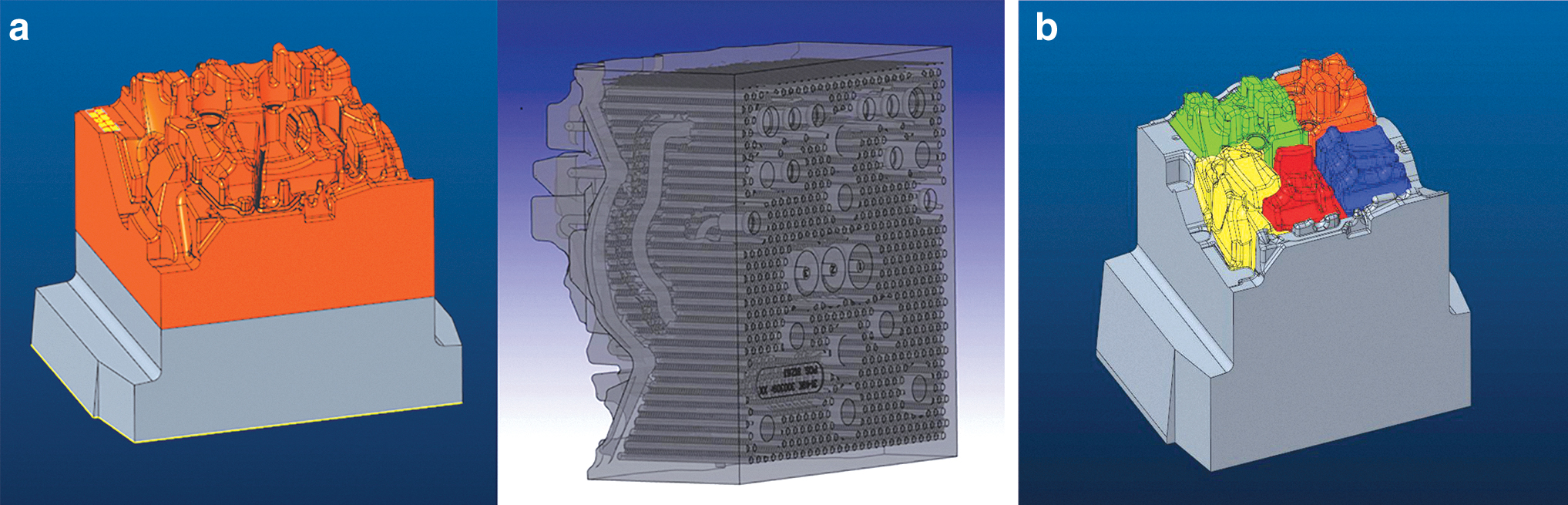
Finally, Figure 22 displays the possibilities of optimizing a given part, which will contribute to a significant reduction in material costs and to a reduction in production time and associated costs. These are the possibilities of optimization using topological optimization (e.g., in Sinico et al 23 ), lattice structure, perforation (Fig. 22a), or segmentation (Fig. 22b). As already mentioned, in part, in Refs.,3,8,16,20,26,27 these are real ways to rapidly reduce the weight of the part and the associated costs of material and production while maintaining the rigidity and functionality of the tool. In the case of perforation, a reduction of production costs by ∼20% can be estimated. In the case of segmentation, printing could take place in smaller segments on smaller printers, and these parts could be interchangeable, that is, in the event of a fault, only the broken segment would be replaced, not the entire slider.
Future optimization steps
On the contrary, it is a merely theoretical idea, as in practice, this idea would be difficult to implement due to the tool's complex force and temperature loading. There would thus be a risk of dimensional instability as a result of which mold penetration could occur.
The expected final savings from the above-described conceptual designs are ∼20% of the part's purchase price. Subsequently, a curve can be created, which describes the increase of the inserted financial means with the increasing number of cast pieces. These costs are necessary for the maintenance and proper functioning of the mold and are based on data collected during casting on the molds concerned (Fig. 23). The prerequisite is a linear increase in costs. The graph shows that the intersection of the cost curve of the current generation of the 3D-printed tool (3D print) and the cost curve of the conventional tool (serial), which indicates the breaking point from when the operation of the 3D-printed tool is cheaper in total, is around 110,000 casted pieces.
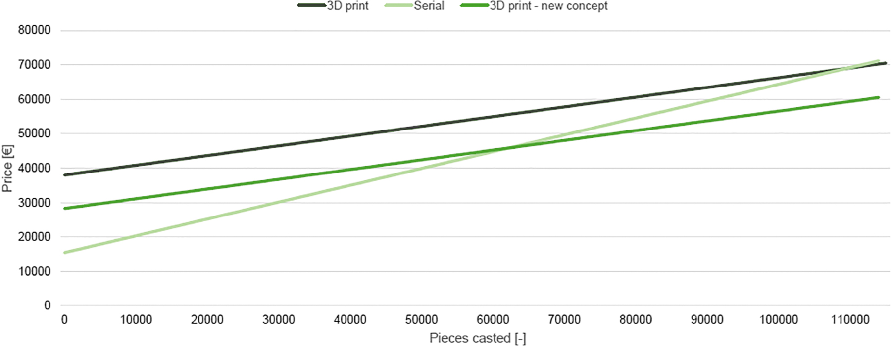
Cost curve depending on the number of castings and the mold concept.
This value is located at or beyond the tool life of the tool itself. In the case of application of the measures described above, the savings for printing the tool were calculated at 20%. This adjustment of the initial investment shifts the entire load curve downward, and the breaking point occurs much earlier on about 60,000 cast pieces. Pieces cast above this limit already generate a profit compared with the maintenance costs of a conventionally produced tool.
Conclusions
In this case study, the production and deployment in a serial production environment of a 3D-printed tool for HPDC were successfully demonstrated, which as a project was already in a way unique for its dimensions and production technology. After all the experiments were performed, the following findings can be stated:
Production of large parts (270 × 270 × 200 mm) using 3D printing is possible, but it is necessary to consider the technological phenomena (deformation, residual stresses), so it is recommended to use an adequate allowance for finishing and respect design rules that designers should follow when designing AM parts.
The use of conformal cooling for such a large part brought a reduction in the tool's temperatures and achieved a uniform temperature field, which contributes to increasing tool life and reducing the number of repairs on the tool (verified by simulations in SW ProCAST and compared with real production records).
Production costs are significantly higher (∼150%) for a 3D-printed tool, mainly due to the high price for the printing itself.
The possibility of reducing production costs through the optimization options that 3D printing brings (perforation, segmentation, topological optimization, lattice structure).
Furthermore, this case study could serve as a demonstration to the 3D printing community that the printing of such large parts is possible with this technology, but it is necessary to consider all the pros and cons, which would subsequently balance the fact that the production costs of making such tools are many times higher than with the conventional solution. Therefore, the authors of this study recommend that before printing similarly large components or implementing similar studies, to consider the design rules for AM and possibly implement one of the options for part optimization (lattice, perforation, topology).
Footnotes
Acknowledgments
The authors would like to thank Aleš Kovář & Filip Koliáš (ŠKODA AUTO a.s.) to their contribution to the research and CTU in Prague for support from the project Complex development of the production process of parts by the methos of metal 3D printing using powder bed fusion, grant number SGS22/158/OHK2/3T/12, Faculty of Mechanical Engineering, Czech Technical University in Prague.
Authors' Contributions
V.A.: Conceptualization, investigation, methodology, formal analysis, visualization, writing—original draft preparation, and writing—review and editing. J.Z.: Conceptualization, investigation, methodology, formal analysis, visualization, and writing—review and editing. L.B.: Conceptualization, investigation, writing—review and editing, supervision, and project administration. P.Š.: Conceptualization and investigation. M.B.: Conceptualization and investigation.
Author Disclosure Statement
No competing financial interests exist.
Funding Information
No funding received.