
Abstract
Concrete is a material favored by architects and builders alike due to its high structural strength and its ability to take almost any form. However, to shape concrete structures, heavy-duty formwork is usually necessary to support the fresh concrete while curing. To expand geometrical freedom, three-dimensional (3D) printed concrete formwork has emerged as a field of research. This article presents one possible application, a novel fabrication process that combines large-scale robotic fused deposition modeling 3D printing with simultaneous casting of a fast-hardening, set-on-demand concrete. This fabrication process, known as “Eggshell,” enables the production of nonstandard concrete structures in a material-efficient process. By casting a fast-hardening concrete in a continuous process, lateral pressure exerted by the fresh concrete is kept to a minimum. In this way, a 1.5-mm-thin thermoplastic shell can be used as a formwork, without any additional support. Geometries of different scales are tested in this article to evaluate the feasibility of the Eggshell fabrication process in an architectural context. An array of printing materials are also tested, and several different reinforcement concepts are analyzed. The findings are used to produce a full-scale architectural demonstrator project. This article shows that a wide range of concrete geometries can be produced in a material-efficient fabrication process, paving the way toward mass customization and structural optimization within concrete architecture.
Introduction
Concrete is, by far, the most used construction material in the world 1 and it has become practically impossible to imagine any building project without it. During construction, concrete needs to be supported by formwork as it transitions from a fluid material into a solid. Fabricating these formworks determines a large portion of the total construction costs of a concrete element, especially for nonstandard shapes (around 50% of costs for a standard element and up to 80–90% for a nonstandard element 2 ). Therefore, although concrete can theoretically be shaped into almost any form, standard, orthogonal structures remain the norm, implying that structures are built with more material then truly needed.
Fused deposition modeling (FDM) three-dimensional (3D) printing of concrete formwork holds promise of enabling shape freedom in concrete architecture; however, so far the construction industry has been slow to adopt digital (fabrication) processes. 3 Some of the reasons that FDM formwork has not yet become widespread are the slow speed of the fabrication process, the typical small scale of prints, and the inability of the thin, fragile printed structures to hold the fresh concrete in place.
“Eggshell” addresses these issues as a novel fabrication method for nonstandard concrete structures. It uses a large-scale, robotic FDM process, combined with a set-on-demand digital concrete casting process developed within the project Smart Dynamic Casting (SDC). 4 Eggshell seeks to enable the fabrication of bespoke, structural building elements in a nonwasteful process, while allowing for the integration of reinforcement.
Relevant work
Over the past decades, many processes have been developed to address the issues of formwork waste and shape freedom in concrete architecture. The most notable of these processes is 3D concrete printing (3DCP), first pioneered as a process called Contour Crafting. 5 Currently, 3DCP is a subject of research at many research institutions and companies worldwide, and the first built examples are appearing.6–8 Although promising as a large-scale fabrication method due to generally high printing speeds, 9 problems remain: particularly in cold joints between layers of printed concrete, 10 and the difficulty of integrating reinforcement. 11 For these reasons, many applications of 3DCP so far have been either non-loadbearing or as lost formworks. 12
To extend fabrication freedom in formwork production, 3D printing has been further explored by several research- and industry projects. Spatial extrusion was used to create formwork by the Mesh Mould 13 project as well as by Branch Technologies. 14 This method is promising, but these concrete structures still have to be manually finished in a post-processing step. Another research project aims at using conventional FDM 3D printers to produce customized formwork parts that can be assembled, using sand or water to counter the lateral pressure from fresh concrete. 15 This work has shown that highly complex parts can be successfully fabricated with a thin, lightweight formwork. 16 However, the process is time-consuming and numerous smaller formwork pieces require assembly, leading to vulnerable joints between pieces.
Counter-pressure casting has also been used by Aectual, a company specializing in 3D printed building products, to create a staircase. 17 An alternative approach to this method is to print a support structure around the formwork, as either a dissolvable 18 or removable spatially extruded formwork. 19 Although effective, printing these supports significantly increases printing time. In general, mitigating the high lateral pressure exerted on formwork remains a challenge for all projects involving FDM 3D printing, especially in elements of a larger size.
One project that has effectively addressed the challenge of controlling lateral pressure on a formwork is SDC. 4 SDC is a robotically driven slipforming system for creating bespoke concrete structures, and a key aspect of the research is the invention of a digitally controlled set-on-demand material process. This allows concrete to enter the formwork in a fluid state and exit in a hardened state. By using a digital casting process and controlling hydration of the concrete, the material at the exit of the moving formwork is able to carry the load of the material above. 20 A clear advantage of SDC process is that conventional reinforcement can be easily introduced. Although SDC has extended the possibilities of digital fabrication with concrete, it is still limited in the range of geometries it can produce, due to complex mechanical actuation needed for the dynamic moving formwork.
Eggshell
The Eggshell concept 21 was developed as a way to address the main limitations of SDC, while capitalizing on its advantages. As such, it merges large-scale robotic FDM 3D printing with the set-on-demand digital casting system developed within SDC. Other process exploiting such casting systems have been proposed and may generally be referred to as Digital Casting Technologies. 22
In Eggshell, by exploiting the casting material chemistry and processing, it becomes possible to use a thin, single-layered shell as formwork without any additional supports or counter-pressure material. Further, by printing the formwork, instead of actuating it as in SDC, a much wider range of geometries can be produced without losing the advantage of being able to include traditional reinforcement in structural building components.
The ultimate objective of Eggshell is to simultaneously print and fill a formwork (Fig. 1). This presents different advantages. First, it offers unrestricted access to the formwork to allow for precise casting and makes it easier to integrate reinforcement during fabrication. In addition, printing the formwork first may lead to a risk of buckling or damage of the formwork if it has to be moved. However, if the printing progresses as the formwork is filled with concrete, the hardening concrete effectively reduces the height to be considered for a risk of buckling.
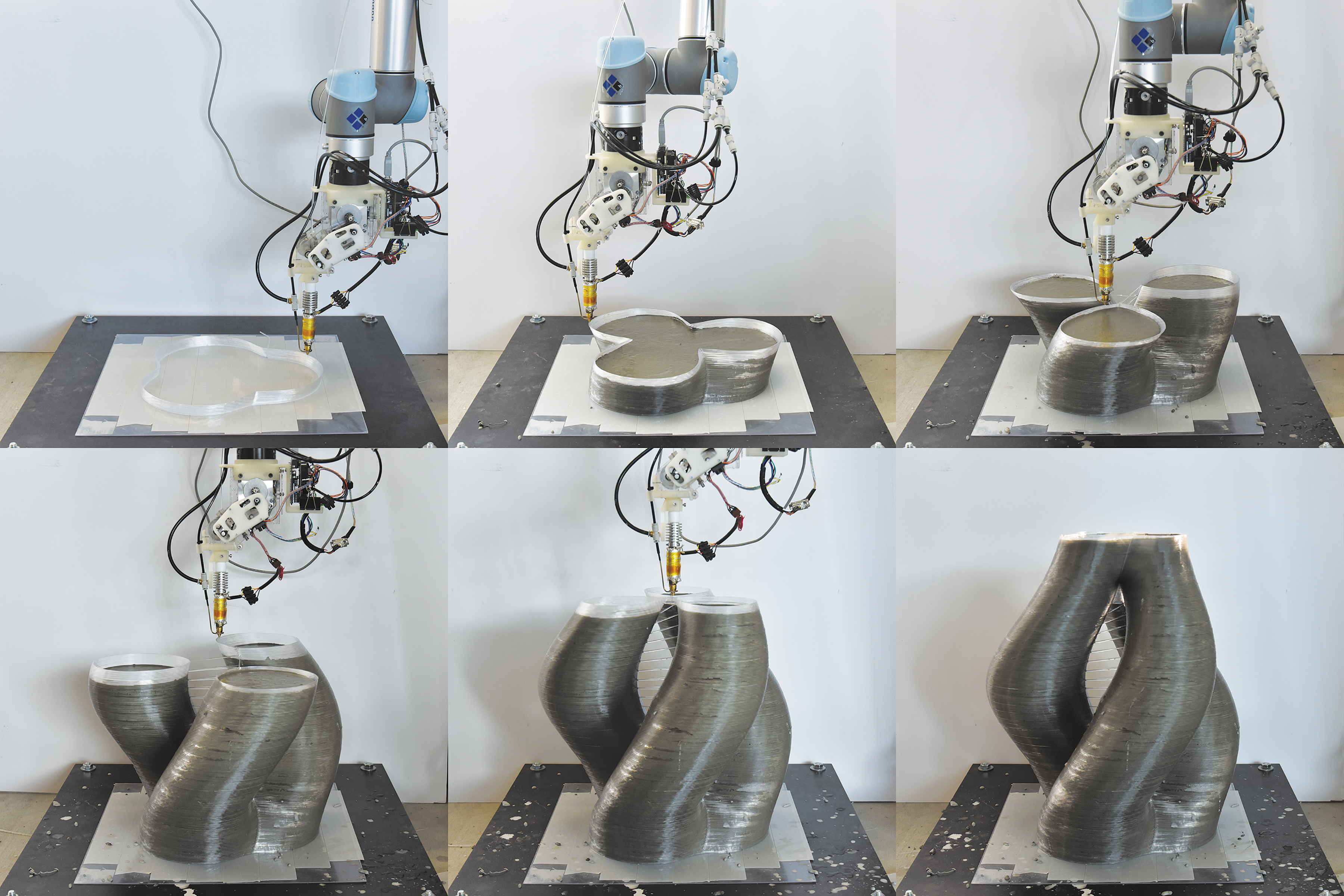
Using the Eggshell fabrication process to produce a concrete column with three branches. Formwork material: polyethylene terephthalate glycol, layer height: 1.0 mm printing speed 25–45 mm/s, total fabrication time: 210 min.
Scope of the study
The original concept of Eggshell, simultaneous printing and filling, has been used to produce the Branching Column (Fig. 5) and the Twisting Column (Fig. 6) described in the Results section. Despite the advantages of using the Eggshell simultaneous fabrication process, it is also possible to print the formwork first and sequentially cast a set-on-demand concrete (consecutive fabrication process). This process has been used to produce the third demonstrator, the Future Tree (Fig. 8).
Connected to the main target of Eggshell is the development of a simultaneous fabrication process where concrete is continuously filled in a digitally controlled process (in-line processing). This process has been used to fabricate the Branching Column; however, for both the Twisting Column and the Future Tree, an off-line concrete processing system has been used in which discrete batches of concrete were manually accelerated and cast. These small batches provide for a good representation of continuous processing, while making it easier to process material in a wide range of cross-sections, as well as compensating for variations in material. From a materials chemistry point of view there is no significant change; however, increasing the robustness of continuous processing remains a topic of ongoing research. Reports on how deactivation and activation of concrete can be achieved are provided elsewhere.20,23
Materials and Methods
The different components of the fabrication setup are shown in Figure 2. They can be divided into three groups: control system (Fig. 2E, F), formwork printing system (Fig. 2H, I), and set-on-demand casting system (Fig. 2A–D). Fundamentally, the Eggshell process involves six steps: (1) designing the geometry, (2) generating the machine code, (3) preparing a batch of retarded concrete, (4) printing the formwork and simultaneous set-on-demand casting, (5) reinforcing, and (6) removal of the formwork and recycling. The setup, as well as the steps in the process are described next.
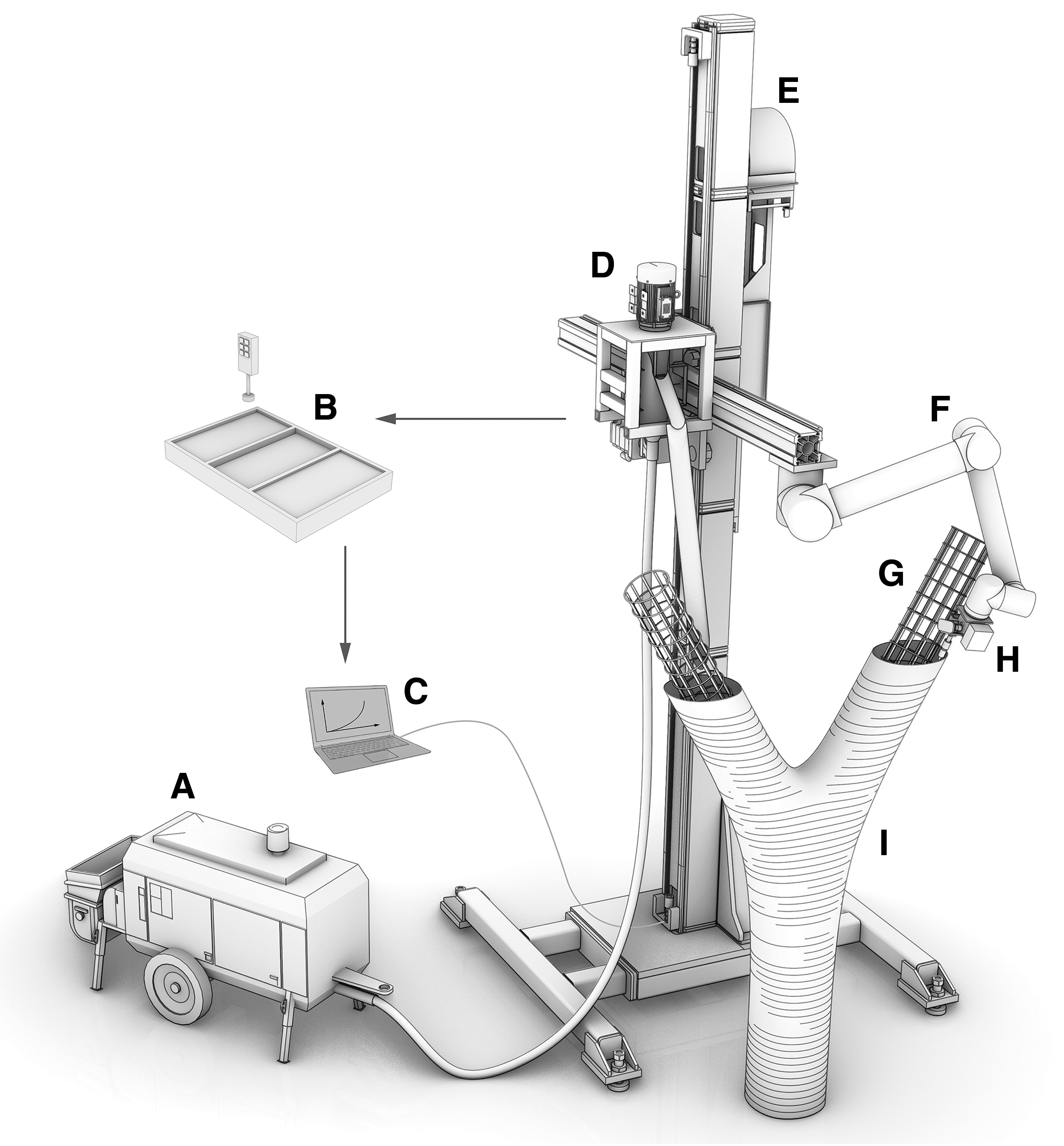
Schematic representation of the Eggshell fabrication process. (A) Concrete pump. (B) Remote material feedback system. (C) Control system. (D) Inline mixer. (E) Vertical linear axis. (F) Six-axis robotic arm. (G) Reinforcement. (H) Extruder end-effector. (I) Three-dimensional printed formwork.
Control system
The moving parts of the setup consist of a six-axis robotic arm (Fig. 2F), mounted to a vertical linear axis (Fig. 2E). This setup offers a building volume of 1.2 × 1.2 × 3.6 m. Despite the use of a robotic arm in this study, a three-axis gantry system would also be sufficient: In the studies presented, the six degrees of freedom offered by the robotic arm are not yet utilized. The robotic arm and axis are controlled through a custom-developed Python interface for the 3D modeling software Rhino 3D's 24 plugin Grasshopper. 25
Design
To aid the design process, a computational tool has been developed in which the user directly generates the toolpaths that define the printed structure. In the tool a starting curve is created and then copied vertically to define the layers of the print. Vertical distance between the curves is defined as the layer height. The curves are then divided into points, with the distance between points defined as the resolution. The result of this can be interpreted as a 2D array of layers and points within the layers. Various transformations such as scaling, rotation, and translation can then be applied to the points to shape the geometry. Multiple contour curves can also be input to create geometries with multiple branches. This design tool offers a direct way to generate fabrication data, with precise control of the printed geometry. This helps to inform the design based on fabrication constraints, such as maximum overhang.
Machine code
The toolpath for the robotic arm and linear axis follows as a direct result of the points generated in the design step. Using a custom Python script, the commands are generated by transforming the points to coordinate planes and adding a printing speed and fillet radius, so that the robotic arm can smoothly transition between corners. The script exports the commands to a JSON file, which has commands for both the robotic arm and linear axis. The extruder code is generated through an Arduino 26 script in which flow rate and nozzle temperature can be set.
Formwork printing
Attached to the robotic arm is an extruder end-effector (Fig. 2H) used for 3D printing the formwork (Fig. 2I). The tool is a self-built filament extruder with a nozzle diameter of 1.5 mm. It uses a standard 2.85-mm filament, has a maximum flow rate of 0.25–0.35 kg/h and a maximum nozzle temperature of 270°C. The extruder motor and heating elements are controlled through the previously mentioned Arduino 26 script.
As a measure of the speed at which structures can be built, vertical printing rate (VPR) is introduced as a parameter. Concrete is always cast in a vertical process and, therefore, the vertical speed is relevant. The VPR is defined as the height of a structure that can be printed within a given time. As the 3D printed formworks consist only of an outer curve without infill (structures commonly referred to as “vases”
27
within the 3D printing community), the VPR at a predefined cross-section of a structure is given by the following formula:
Typically, layer height and printing speed are kept constant during the fabrication process. Depending on the geometry of the printed structure, the perimeter typically varies over the height, meaning that the VPR varies with it.
To start the printing process, the JSON file generated in the previous step is executed on a computer connected to the vertical linear axis and robotic arm. In case of a simultaneous process (such as in the first and second demonstrators), the formwork is then filled with accelerated concrete while it is being printed.
Set-on-demand casting system
The set-on-demand casting system used by the Eggshell process has been adopted from the SDC project. 4 Three different mix designs were used throughout this article, and they are provided in Supplementary Table S1. The general principle is that a large batch of retarded concrete is mixed, ensuring its workability for up to 8 h. Then, incremental volumes of the retarded concrete are taken and activated by adding small amounts of accelerator (dosage and source provided in Supplementary Table S1). As mentioned earlier, this has been done in a method of in-line, digital processing for the first demonstrator and in an off-line, manual method for the second and third demonstrators.
Reinforcement
As concrete is strong in compression but weak and brittle in tension, reinforcement is necessary to resist tensile forces and to produce load-bearing, code-compliant concrete elements. Eggshell presents a wide range of possibilities, in which the reinforcement can be:
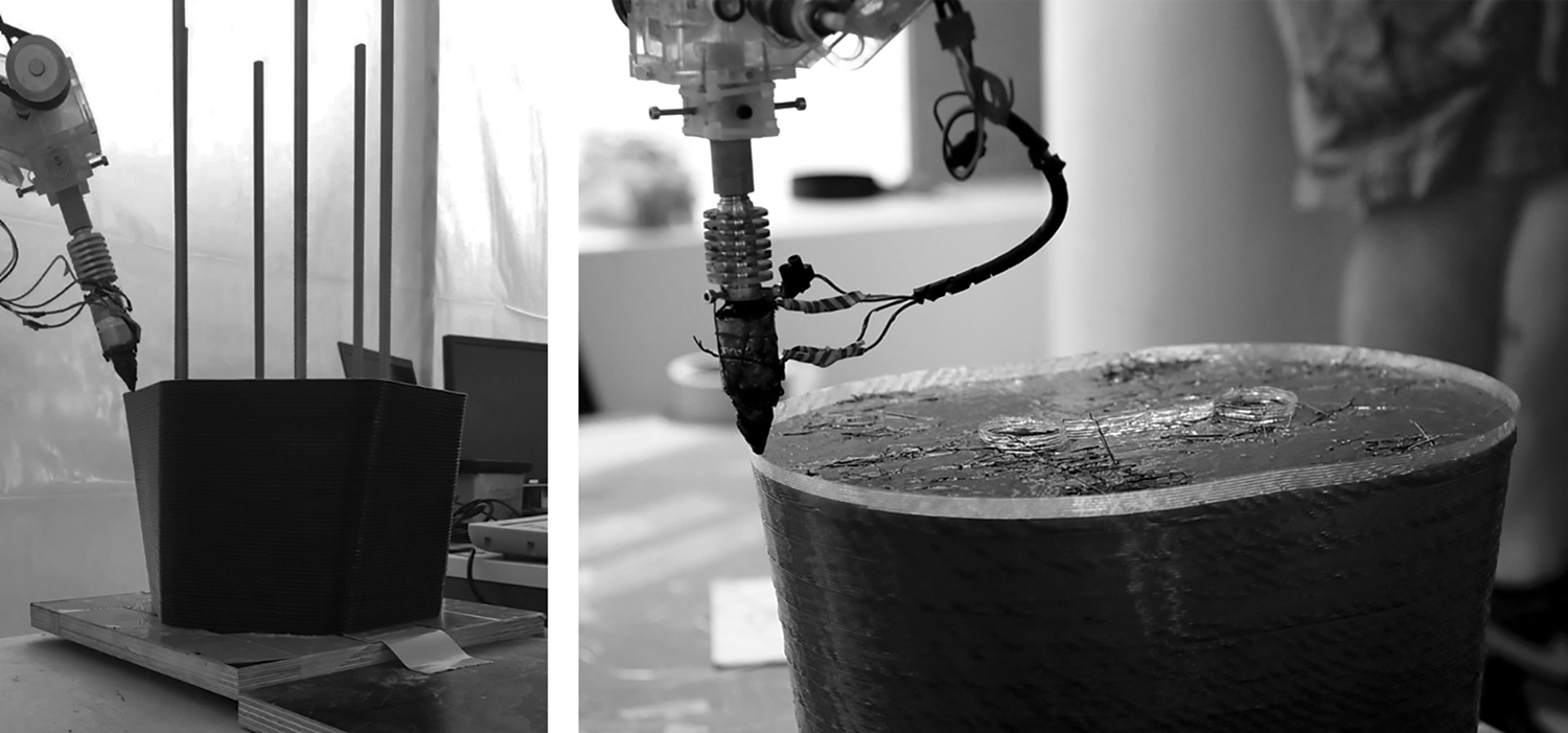
Arranged before the concrete production (either before, during, or after printing the shell formwork) (Fig. 3A),
Left: printing around preplaced reinforcement. Right: placing fibers in between casting layers and integrating post-tensioning ducts. I) Added to the concrete matrix itself (e.g., using short pumpable fibers), II) Placed in between casting layers (e.g., using hooked fibers) (Fig. 3B), or V) Post-installed in prefabricated ducts (e.g., using post-tensioning reinforcement) (Fig. 3B).
The first approach is the closest to standard reinforced concrete solutions found on most construction sites. This allows the use of conventional reinforcement and design methods, but it might limit geometric freedom as the reinforcement cannot be precisely prefabricated to fit very complex geometries. 28 Further, for this to be used in a simultaneous fabrication process, the robotic arm would have to move around the preplaced reinforcement (Fig. 3A), adding complexity in robotic path planning.
The use of fibers in the fabrication process [approaches (II) and (III)] expands the design space to more complex geometries. However, mixing fibers into the concrete matrix (II) complicates concrete processing and requires short, expensive fibers. These issues might be overcome by splitting the continuous casting process into several steps and placing fibers in between these casting steps (III), which additionally allows for aligning and grading the fibers according to structural needs (Gebhard, L., Mata-Falcón, J., Markić, T. and Kaufmann W. “Aligned interlayer fibre reinforcement for digital fabrication with concrete,” in RILEM-fib X International Symposium on Fibre Reinforced Concrete, BEFIB2020, Valencia, 2020. Abstract submitted).
Since fibers do not provide sufficient strength and ductility by themselves, they should be complemented with additional post-installed reinforcement [approach (IV)]. Post-tensioning reinforcement can be easily implemented by using empty ducts left during the Eggshell production. These ducts also allow casting a strain-hardening fiber-reinforced material (e.g., Ultra-High-Performance Fiber-Reinforced Concrete) into them, which is an alternative to post-install reinforcement that is well suited for elements with highly complex geometries. The ideal reinforcing solution for a certain application will involve one or several of the presented reinforcing approaches depending, among other factors, on the complexity of the geometry.
Removal of the formwork
Although the concrete material is self-supporting within 1–2 h, leaving the formwork in place for a longer period results in better curing conditions. After 1–3 days, the formwork can be removed by using a heat gun and pliers. Any traces of concrete must then be washed off before the material can be recycled. Although recycling of the formwork is theoretically possible, this has not yet been experimentally verified.
Results and Discussion
Eggshell aims at innovating the production of full-scale, architectural elements. Initial studies were aimed at establishing fabrication parameters. Subsequently, concrete structures in different scales were fabricated, concluding with a structure implemented in an architectural context.
Process development
Vertical printing rate
A first study was aimed at selecting a material and tool that would have optimal results for the process. Different combinations of layer height and printing speed were tested together with different materials, to achieve the highest VPR with good print quality. Three materials were tested: polylactic acid (PLA), polypropylene (PP), and polyethylene terephthalate glycol (PET-G). PLA was printed by using a Flexion Extruder 29 desktop 3D printer at high printing speed (40–80 mm/s) and low layer height (0.3–0.5 mm); PP was printed at low printing speed (6–10 mm/s) but high layer height (5–7 mm) by using a BAK Dohle ExOn 3A industrial plastic welder. 30 PET-G was printed at an average printing speed (30–50 mm/s) and an average layer height (0.8–1.2 mm), by using the self-built filament extruder. The results are presented in Table 1.
Maximum Vertical Printing Rate That Could Be Obtained with Different Materials and Tools, Assuming a Constant Perimeter of 1000 mm (Straight Column of 250 × 250 mm)
The experiments using PP gave the highest VPR, as they used an industrial plastic welding machine with a 5-mm-diameter filament and a 10-mm nozzle. However, as this extruder nozzle diameter was large, material usage was extremely high. It also resulted in a relatively thick (10 mm) wall, which is more difficult to remove and less aligned with the concept of a thin shell. The tests using PLA resulted in the lowest VPR. The best results were achieved with PET-G and the self-built filament extruder previously described, by using a layer height of around 1.0 mm and a printing speed of around 50 mm/s. PET-G generally offers better chemical resistance than other common 3D printing thermoplastics and is, therefore, better suited for use in combination with concrete. 31 All further tests were, therefore, conducted by using PET-G.
Controlling thermoplastic layer-to-layer bonding
A critical aspect for successfully filling such formworks with concrete is avoiding delaminations and weaknesses between the FDM printed layers. Issues with delamination were encountered for larger prints, in particular for the Future Tree. This is best explained by shrinkage of the material: As an extruded layer of filament cools more from the top, it contracts, causing the edges to warp upward. The problem is complex due to heat conduction between the printed layers; however, examining the details of the underlying physics goes beyond the scope of this article. Instead, a pragmatic solution is proposed, allowing Eggshell to be used for large-scale fabrication.
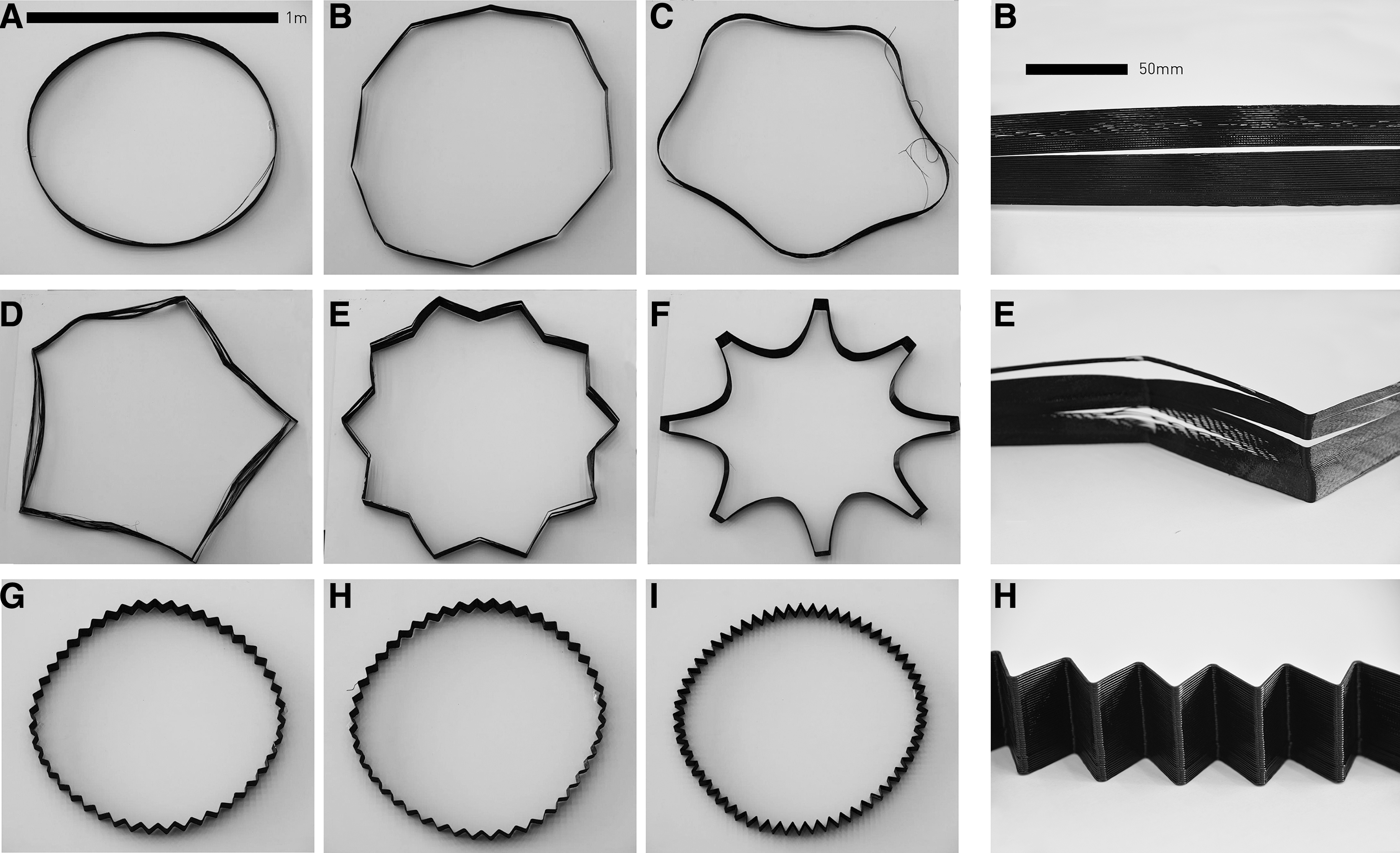
The problem of delamination scales with the size of the print, so larger prints have larger absolute deformations. 32 Further, as the filament shrinks mostly in the longitudinal direction of the layer path, the warping effect can concentrate in corners. 33 To study this behavior, various geometries with a diameter of 1 m were printed by using a layer height of 1.0 mm and a printing speed of 45 mm/s. Tested geometries included a circle (Fig. 7A), regular polygons (Fig. 7B), star polygons (Fig. 7D, E), polygons with filleted edges (Fig. 7C), n-gon (Fig. 7G–I), and a section of the Future Tree column design (Fig. 7F).
It was found that, by applying a zigzag or chevron pattern to the geometry, detrimental shrinkage could be avoided (Fig. 7G–I). As the straight sections in these geometries are short, forces acting on the corners due to shrinkage are low. This pattern may also result in a higher flexibility in the structure (allowing minor deformations before delaminating), although the final printed shape did not show substantial difference with the planned printing path. Higher resolution measurements will be necessary in the future to give more attention to this problem. Further, the printing speed in corners is not changing substantially, so this should not be considered as denser zones offering “anchor points.”
These results indicate that the maximum length of a straight edge should not exceed 70 mm, to print the formwork without layer delamination. This was used as an input to generate the final design of the Future Tree. For the other two structures, having smaller dimensions, this was not necessary.
Overhang
To define the geometric possibilities of the Eggshell process, a set of experiments were conducted to determine the maximum possible overhang. Four models with a height of 300 mm and overhang angles ranging from 15° to 45° were printed in PET-G, using a constant printing speed of 45 mm/s and a layer height of 1.2 mm. They were then filled with a set-on-demand concrete in 100 min (3 mm/min). These tests showed that an overhang of 35° could be successfully filled. However, breakage occurred in the 45° model after filling to 100 mm in height. 34
A later study showed that it was also possible to print and fill volumes of a smaller diameter with an overhang of 65° by changing the printing speed based on the angle between layers. 35 In case of a larger overhang, one can print more slowly while keeping the flow rate constant to deposit more material in one place and create a stronger bond between layers. Thus, using a printing speed ranging from 20 to 40 mm/s, structures with a wide range of overhangs can be printed.
Filling rate
The minimum and maximum concrete filling rates to avoid cold joints and formwork breakage were established. Due to printing speed limitations it was impossible to reach a VPR higher than 4.2 mm/min, so geometries were preprinted and then filled with concrete (setting time of 60 min) at different filling rates. Figure 4 shows the results of this study, illustrating how a low VPR (<2.5 mm/min) results in cold joints in the concrete, whereas a high VPR (>7.5 mm/min) results in breakage of the formwork. This means that VPR and concrete filling rate should be kept in between 2.5 and 7.5 mm/min for concrete with a setting time of 60 min. This also illustrates how a high VPR can only be successfully achieved with concrete with a faster setting time. Recent developments have already led to material mixes with a faster setting time; however, these are not described in this article.
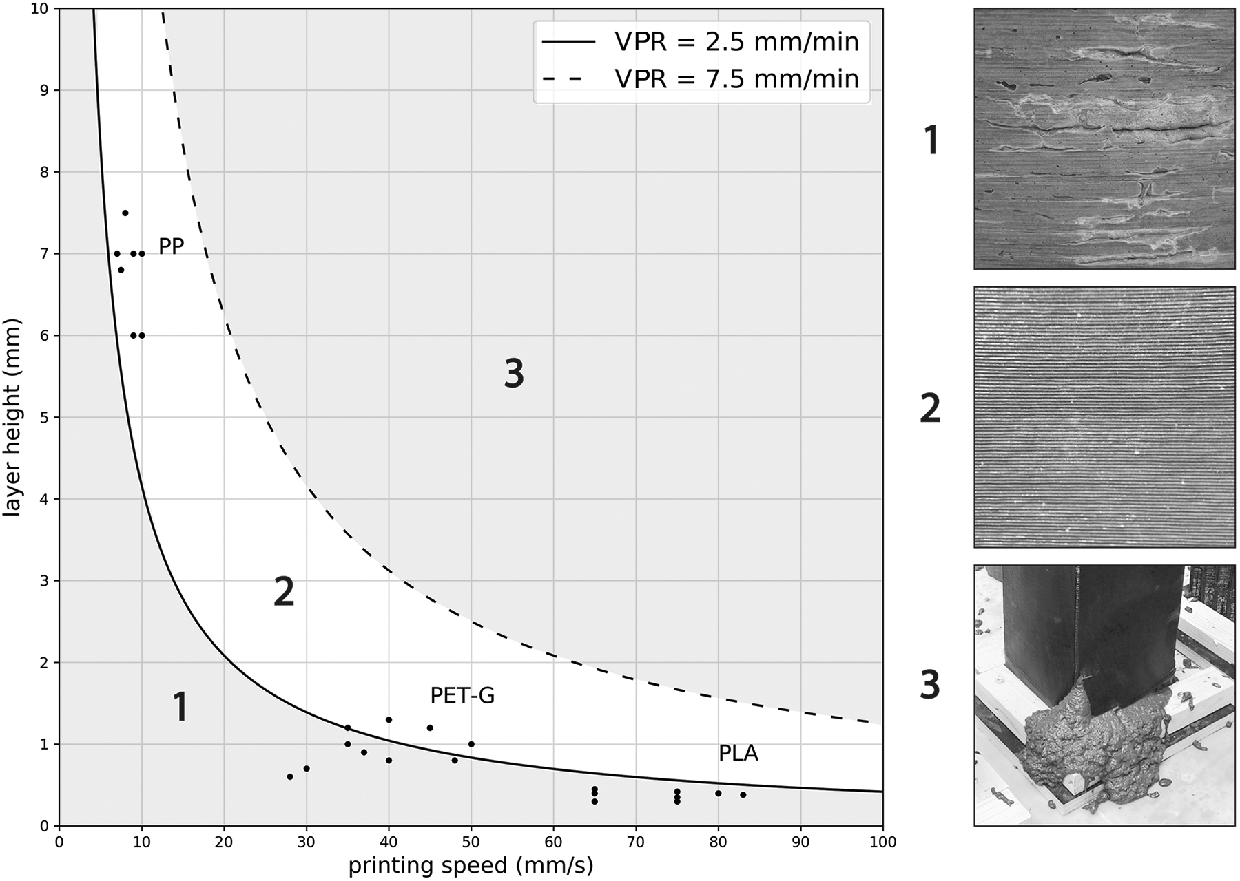
Printing speed plotted against layer height. The continuous line shows a VPR of 2.5 mm/min, and the discontinuous line shows a VPR of 7.5 mm for a straight column with a constant perimeter of 1000 mm. Area 1 indicates a VPR of 0 < 2.5 mm/min, resulting in cold joints between layers, area 2 indicates a VPR of 2.5 < 7.5 mm/min, resulting in a satisfactory surface quality, and area 3 indicates a VPR of >7.5 mm/min, resulting in breakage of the formwork. The three groups of data points indicate the parameters of the experiments on VPR from the first section in this chapter. VPR, vertical printing rate.
The rate at which concrete is placed should be analyzed in terms of rate of rise, analogous to the VPR and related to the rate at which the material should harden. However, from a processing point of view, we have to consider the cross-section area, which multiplied by the vertical filling speed gives a volumetric filling rate. Since concrete pumps have limited flexibility in the volumetric flow ranges, this puts a limit onto the range of cross-sections that can be produced with a certain device.
As both the Twisting Column and the Future Tree had large variations in cross-section, the off-line, manual filling process was used to fill these structures. In this process, discrete volumes of concrete are mixed and placed manually in the formwork. The volumes of these mixes are adjusted in relation to the cross-sectional area, so that each of the added layers does not lead to an excess pressure that could damage the formwork. The added volumes should also be limited to reduce the time between additions and avoid cold joints being produced such as in 3DCP.10,36 For Eggshell, however, the risk is much lower as the subsequent concrete layers are not as stiff. The problem is further reduced if in-line, continuous filling can be applied.
Demonstrators
Branching Column
After parameter calibration, studies were aimed at providing a proof of concept for the method. A 1600-mm-tall prototype (Fig. 5) was printed and filled in 450 min, giving an average VPR of 3.55 mm/min with a layer height of 1.2 mm and printing speed of 45 mm/s. Simultaneously, concrete was cast every 5 min in layers ranging from 10 to 30 mm. The in-line material processing system was used; however, concrete was manually cast into the formwork. As the VPR was higher than 2.5 mm/min, no cold joints could be seen between layers.
One thousand six-hundred-millimeter-tall early prototype, printed in 450 min with a layer height of 1.2 mm, printing speed of 45 mm/s, and average VPR of 3.55 mm/min.
Twisting Column
The aim of the second demonstrator was to demonstrate the possibility of simultaneous fabrication to produce complex geometries. Moreover, as designs for structurally optimized geometry often feature multiple branches (multiple contours per layer), several models with a branching typology were fabricated. Such geometries inherently call for alternative reinforcement solutions and, thus, the applicability of post-tensioning was tested.
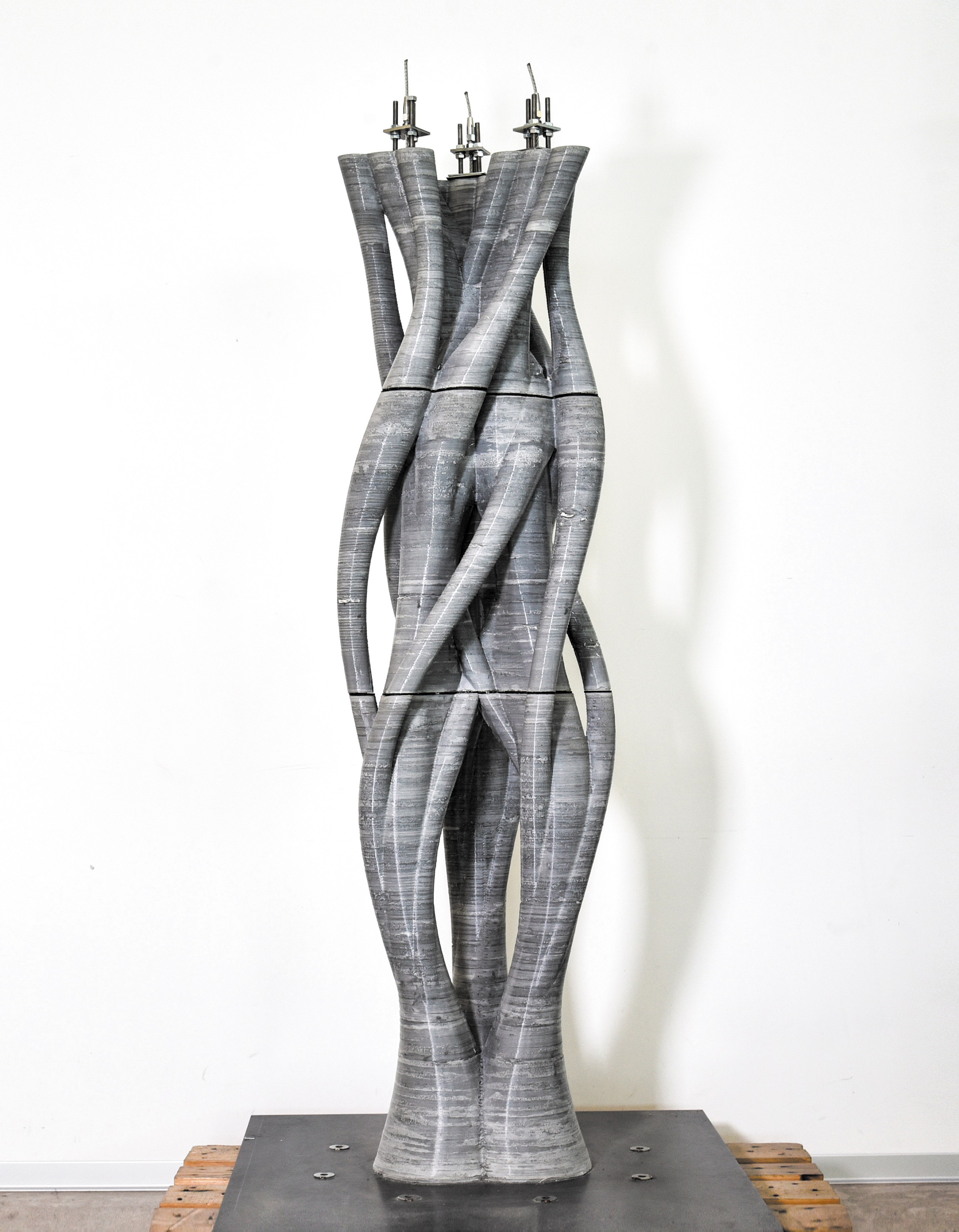
In the development process of this demonstrator, models with three branches (Fig. 1) and five branches were fabricated. The final structure with up to 12 individual branches (Fig. 6) was printed in three separate elements that were then assembled with post-tensioning. This opens up interesting perspectives for Eggshell, allowing geometries to be fabricated that are clearly difficult to produce otherwise, at least in an efficient way. These designs were not structurally optimized, but they show the geometrical possibilities of the process.
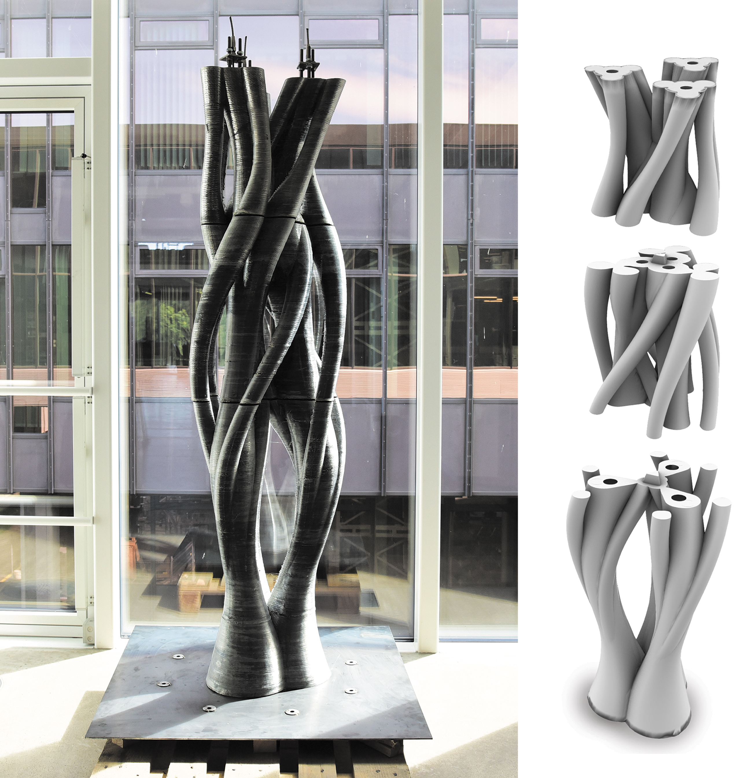
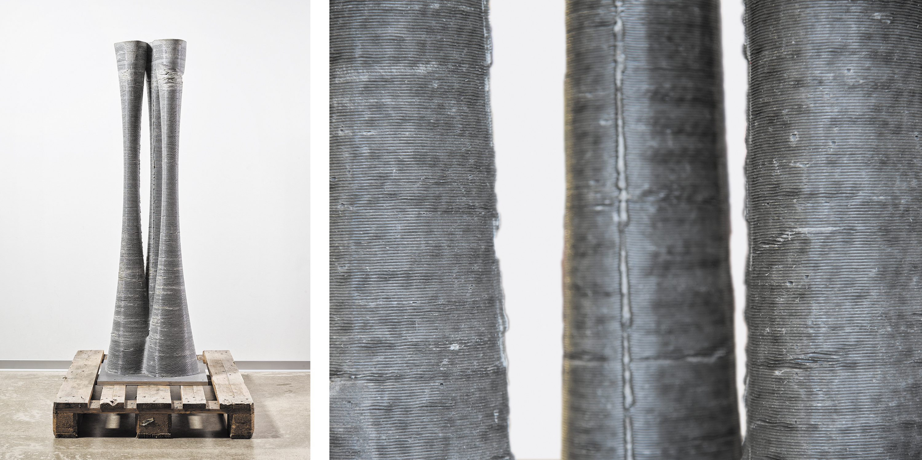
Left: 1800 mm tall Branching Column fabricated in three parts by using a simultaneous process. Layer height: 1 mm, printing speed: 30–50 mm/s, fabrication time of parts (bottom to top): 12, 10, 7 h. Right: Void spaces are printed inside the three main branches so that cables can be inserted post-fabrication to tension the elements together. Design and fabrication: A. Barney and W. Yang.
Left: different printing tests with a diameter of 1 m, printed with a layer height of 1 mm and printing speed of 50 mm/s. Right: close-up of printed layers.
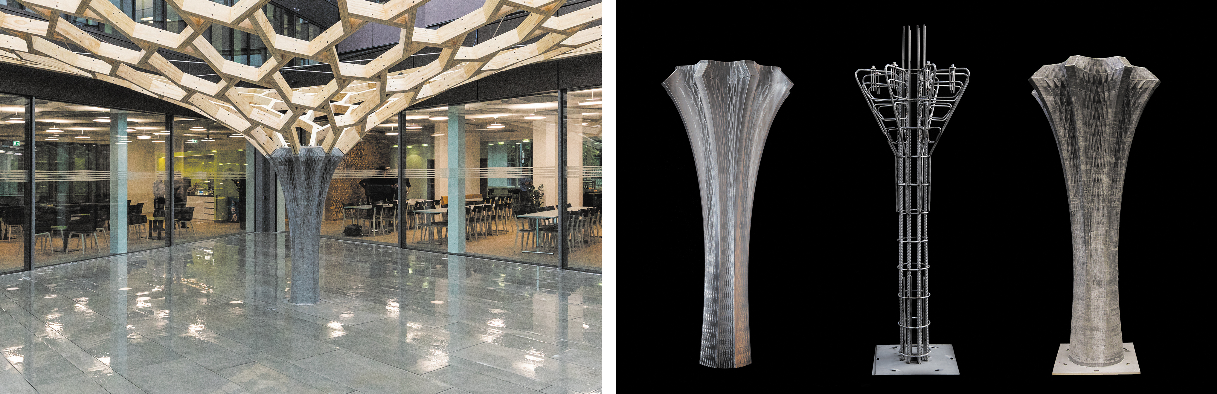
Left: completed Future Tree pavilion (Image: Basler & Hofmann AG, Stefan Kubli). Right: printed formwork, reinforcement cage, and finished concrete element.
Future Tree
To show the possibilities of large-scale fabrication, a concrete column was chosen as an architectural demonstrator project. The column is part of the Future Tree pavilion commissioned by Swiss engineering firm Basler & Hofmann. 37 For this project a concrete column was prefabricated with a height of 2.1 m and top and bottom diameters of 1 and 0.4 m, respectively. The main challenges that had to be addressed were the integration of reinforcement, shrinkage of the 3D printed filament at large scales, difficulty of resisting lateral pressure of the concrete due to the lower surface to volume ratio, and tolerance of connection details (Burger, J., Lloret-Fritschi, E., Taha, N., Scotto, F., Demoulin, T., Mata-Falcón, J., Gramazio, F., Kohler, M. and Flatt, R. J. “Eggshell: Design and Fabrication of a Non-Standard, Structural Concrete Column Using Ultra-Thin, 3D-Printed Formwork.” in Digital Concrete 2020, Eindhoven. Abstract accepted).
For a formwork of this size, layer delamination during printing presented a major challenge. Solutions for this issue are discussed in the Section: “Controlling layer to layer bonding and avoiding delamination.” The final column formwork was continuously printed over a period of 26 h with a layer height of 1.0 mm and printing speed of 45 mm/s, resulting in an average VPR of 1.34 mm/min. As the VPR was too low to be cast and printed simultaneously, this was done by using the consecutive process.
After printing the formwork, the prefabricated reinforcement cage was placed inside and the formwork was filled with concrete in 8 h, resulting in an average concrete filling rate of 4.3 mm/min. This clearly illustrates the discrepancy between speed of 3D printing and concrete filling. To be able to fill this structure simultaneously, the VPR needs to increase by at least a factor of 2. Nevertheless, the Future Tree column demonstrates a first architectural application of the Eggshell consecutive process: using a thin 3D printed formwork with set-on-demand concrete casting.
Conclusions and Next Steps
This work presents a novel fabrication process that aims at realizing nonstandard concrete structures in an effective and sustainable way. Although the research is still in its early stages, it has shown that objects of a scale relevant to architecture can be fabricated. The Eggshell simultaneous fabrication process shows potential for making a wide range of geometries possible, but its success will depend on whether printing can be sped up. Achieving a faster vertical formwork printing rate is necessary to fabricate objects of a larger scale without causing cold joints. There are, however, several possibilities of increasing speed, by making use of either large, high-output extruders38,39 or state-of-the-art extrusion techniques. 40
Using formwork prefabrication and set-on-demand concrete casting, it is already feasible to produce full-scale elements. However, there are limits on the geometrical potential of this consecutive fabrication method, as complex geometries may not allow the concrete to flow and self-compact well in the formwork. Also, fitting a prefabricated reinforcement cage within a printed formwork can restrict the geometry of the formwork. Indeed, the issue of reinforcement in digital fabrication with concrete requires broader attention. Concepts presented here offer complementary solutions to already existing ones.41,42
To achieve the most sustainable process possible, we are improving the recyclability of used formworks, and examining alternative printing materials. To make the process economically viable and less labor intensive, research efforts should also be directed toward a fully automated concrete casting process, eliminating the need for human intervention. As research progresses and the process is stabilized and streamlined, the range of building components produced could extend to beams, floor slabs, or connecting and transitional elements, paving the way toward sustainable mass customization in concrete architecture.
Footnotes
Acknowledgments
The authors thank Tobias Ulrich and Martin Wermelinger for the successful collaboration resulting in a patent for the Eggshell concept, as well as Antonio Barney and Wenqian Yang for their master thesis as part of the MAS Digital Fabrication. Timothy Wangler and Lex Reiter are thanked for their input and fruitful discussions. Lastly, Heinz Richner, Andreas Reusser, Michael Lyrenmann, and Philippe Fleischmann are acknowledged for their technical support.
Author Disclosure Statement
The Eggshell concept was filed as a European Patent Application under patent no. WO 2019/121316 A1. 21
Funding Information
This research was supported by the NCCR Digital Fabrication, funded by the Swiss National Science Foundation (NCCR Digital Fabrication Agreement no. 51NF40-141853).
References
Supplementary Material
Please find the following supplemental material available below.
For Open Access articles published under a Creative Commons License, all supplemental material carries the same license as the article it is associated with.
For non-Open Access articles published, all supplemental material carries a non-exclusive license, and permission requests for re-use of supplemental material or any part of supplemental material shall be sent directly to the copyright owner as specified in the copyright notice associated with the article.