
Abstract
Three-dimensional (3D) models are essential for visualization and conceptual understanding of complex architectures such as protein structure. Although there is a plethora of software platforms that allow digital depictions of protein structure at an atomic level in silico, physical models are needed to convey an intuitive understanding of biomolecular architecture. However, it is a challenge to represent all the relevant features of proteins in a single physical model due to their sheer structural complexity. Here, we describe a modular protein model that focuses only on representation of the secondary structure—the underlying structural skeleton. The simplified model consists of amino acid units, which can be linked together to reproduce the two most fundamental structural features of protein secondary structure: the relative positions of the amino acid alpha carbon atoms, and the intra-main chain hydrogen bonding pattern. We use 3D printing and magnets to create a set of three modular amino acid building blocks, which when linked together into a chain, can faithfully represent alpha helices, beta sheets, and turns. These simple to make models can be used to quickly assemble the alpha carbon trace of an entire protein domain, which conveys a tactile experience of the complexity of protein skeletal architecture. These models highlight the modularity of protein structure: where a single structural unit, the amino acid, can be linked together to form a larger, regular secondary structure. These models also have a propensity to spontaneously organize into alpha helices and beta sheets, as demonstrated by their ability to autonomously assemble when placed in a circulating water tank. These models provide a missing educational tool to expand knowledge of protein structure, foster deeper insight into protein folding, and inspire greater interest in biomacromolecular architecture.
Introduction
The myriad of intricate molecular and nanoscale architectures found in the world of proteins are responsible for key functions essential to life, such as molecular recognition and catalysis. Protein structure is dictated by the spatial arrangement and interplay of multiple simultaneous chemical interactions within a polypeptide sequence, making them difficult to fully understand and appreciate. 1 The study of polypeptide folding and structure formation is imperative to gaining further insight to the behavior and function of nature's machinery. 2 Three-dimensional (3D) representations of these macromolecules are essential to the understanding of the structures, and thus, there are a host of computational tools available to enable researchers to interact with virtual computer-generated representations of proteins. While these tools play a vital role, there is a surprising lack of physical molecular protein models that could provide a more tangible and intuitive way to visualize, learn, and appreciate the subtleties of protein architecture.
3D models have already been widely employed by researchers and educators across various scientific disciplines to encourage user engagement, enhance understanding of structural biology, and to facilitate intuitive communication of ideas.3–6 With the advent and proliferation of 3D printing, there has been renewed interest in representing a wide variety of complex biological and chemical shapes to allow for a tactile learning experience. 7
Organic chemistry and structural biology, which are inherently 3D sciences, are ideally positioned to benefit from physical models.8–10 For example, Meyer reported on laboratory curriculum to create an entire 3D-printed leucine zipper domain, starting from simplified Protein Data Bank (PDB) files, and the molecular graphics system, PyMOL. 10 Others have been able to reach a higher level of molecular detail by representing some of the key atomic interactions. Assemble-And-Match, a novel hybrid tool pioneered by Tavousi et al., extracts information about molecular structures from protein data and generates CAD models of receptor and ligand components. 11 Paukstelis introduced MolPrint3D, a software tool that splits digital ball-and-stick molecular representations into printable fragments that can be readily assembled into tangible models used to aid in education. 12
Many investigators have moved beyond only representing static structure and have used models to portray self-assembly and chain folding.13–15 An excellent example of this is Olson's poliovirus capsid model. It represents a coarse-grained model of viral protein structure, which is composed of 12 identical pieces that can spontaneously assemble into a symmetrical spherical capsid via magnetic interactions when shaken in a closed container. 16 This work conveys several important principles of the self-assembly process. It demonstrates that random collisions can lead to ordered structures, that a higher density of parts (analogous to an increase in temperature) favors assembly, and that misassembly corrections are governed by the structure's ability to break apart and reform. This successful mimicry of the spontaneous molecular assembly of the poliovirus contributes to the understanding of how such natural processes occur in biology.
Peppytides are another example of a dynamic multicomponent physical model, designed to portray the molecular flexibility and foldability of the peptide chain. 17 It features a coarse-grained representation of the peptide backbone, consisting of 3D-printed, dimensionally accurate space-filling pieces, rotatable bonds, and magnetic hydrogen bond donors and acceptors that enable the interchangeable formation of alpha helices and beta sheets. Although these models effectively showcase the dynamic conformational properties of protein chains, its multiple degrees of freedom make it hard to manipulate longer chains and can be overwhelming to novice students unfamiliar with the molecular details of protein structure. We realized that there is a need for a new, simplified molecular protein model made from modular building blocks (amino acids) that would reveal the most universal, underlying aspects of protein architectures and be simple enough to readily assemble entire protein domains.
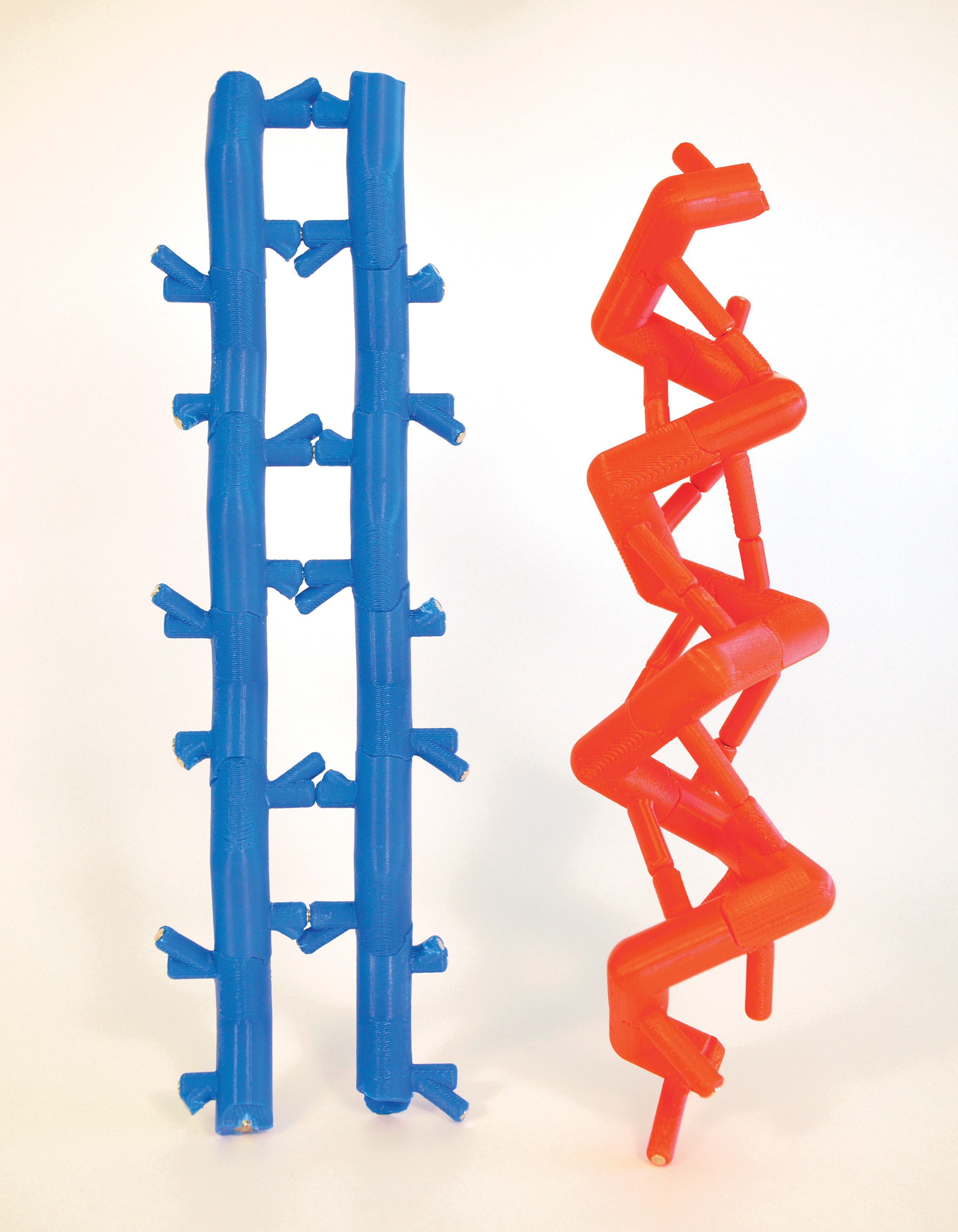
Here, we set out to develop a new, simplified protein model that accurately represents the two fundamental secondary structural motifs, the alpha helix and beta sheet, to enable the efficient construction of a larger protein structure. Secondary structure is most readily visualized by inspecting the alpha carbon trace (Fig. 1). The alpha carbon (Cα) trace, or protein skeleton, is defined as a vector that connects all alpha carbons in sequence and has long been recognized as a useful and simplified representation to structurally classify protein architecture.18–21 Therefore, we focus here on dimensionally accurate modular subunits, we call Skeletides, that can (1) link together in predefined geometries using strong magnetic interconnects to create the alpha carbon skeletal backbone and (2) form long-range hydrogen bonds through weaker magnetic interactions. Side chains were omitted to draw attention to the underlying backbone architecture and to simplify construction. Three amino acid pieces are required to represent the Cα trace in this way: an alpha helix, a beta sheet, and a flexible turn piece. Because the models are preorganized to form their particular secondary structure, assembly is rapid and even spontaneous under certain conditions. These models provide a clear visualization of the highly conserved skeletal framework of secondary structures.
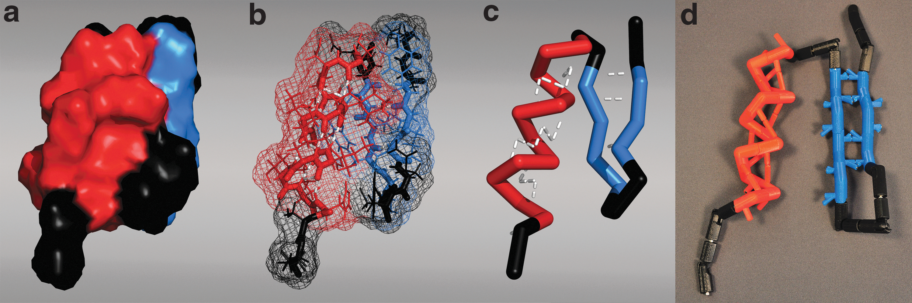
Proteins have complex, folded 3D architectures that can be depicted in graphics software to represent various attributes. Here, a variety of representations are shown for the zinc-finger domain (PDB: 5znf) where the alpha helix is red, beta sheets are blue, and the turns are black:
Materials and Methods
After designing the three separate amino acid pieces on CAD software, we exported the models as 3D stereolithography Standard Tessellation Language (STL) files to send to a 3D printer. The CAD software, 3D printer model, STL models, and printing procedures are provided in the Supplementary Data. We printed each type of piece a different color according to the class of secondary structure formed (alpha helix = red, beta sheets = blue, turn pieces = black) to better visualize the different secondary structure elements present in a folded polypeptide chain. After printing the alpha helix piece (AlphaHelixSTL.stl), we used a reference magnet with its poles labeled to identify which side of the neodymium magnet needed to be inserted into a given terminus. For the alpha helix piece, we used two 3/16″ diameter × 1/8″ deep neodymium rod magnets and pushed them completely into the C- and N-terminal holes of each piece. We then inserted two 1/8″ diameter × 1/8″ deep neodymium magnets into the holes on top of the hydrogen bonding poles, matching the north and south poles of the linkage magnets. For the beta sheet piece, we followed a similar assembly procedure (BetaSheet.STL.stl), but we used four total 1/8″ diameter × 1/8″ deep neodymium magnets to insert into the four hydrogen bonding poles. Finally, for the turn piece, we inserted two 3/16″ diameter × 1/4″ deep neodymium magnets into the N-terminus, where it should protrude, and into the C-terminus, where it fits the hole perfectly. For the Skeletide models used in the self-assembly trials, we used two 1/8″ × 1/8″ neodymium magnets for the C- and N-terminal Reversible Specific Angle Linkages (RSALs) of each piece, and 1/16″ × 1/16″ magnets for the hydrogen bonding poles (Supplementary Fig. S1).
We examined the self-assembly process in a custom-made circulating water tank (Supplementary Fig. S2). Each self-assembly trial was performed with 50 identical pieces (either alpha helix or beta sheet). To initiate assembly, all pieces were laid in an orderly array at the bottom of the chamber to avoid any preformed magnetic interactions, after which the pump was turned on. Photos of the assembly process were taken with a Nikon D90 camera at 1-min intervals over a course of 2 h. From these photos, several self-assembly parameters were manually extracted, including number of correct H-bonds, number of nonspecific bonds, length of correctly form strands, and the number of alpha helices and beta sheets. A total of three self-assembly trials were performed for each set of pieces.
Results and Discussion
Model design
We chose to use the alpha-carbon trace as the basis for this model, instead of an all-atom depiction, to clearly represent the underlying chain shape and hydrogen bonding pattern. Even though some structural details are not represented in a Cα trace, its great advantage is that it is highly conserved in protein secondary structures across the entire PDB. 18 Similar to how peptide conformation can be fully described by analysis of the monomer dihedral angles in a Ramachandran plot, a protein Cα trace can be described by its two fundamental angles 22 : a backbone angle (formed by three adjacent Cαs) and a pseudodihedral angle 23 (formed by four adjacent Cαs) to create a pseudo-Ramachandran plot (Fig. 2b). When we examine a histogram of the distribution of these two angles over 8000 high-quality protein structures from the PDB, 24 we can see how the vast majority of proteins all share very clear domains that describe the alpha helix and the beta sheet secondary structures (Fig. 2b).
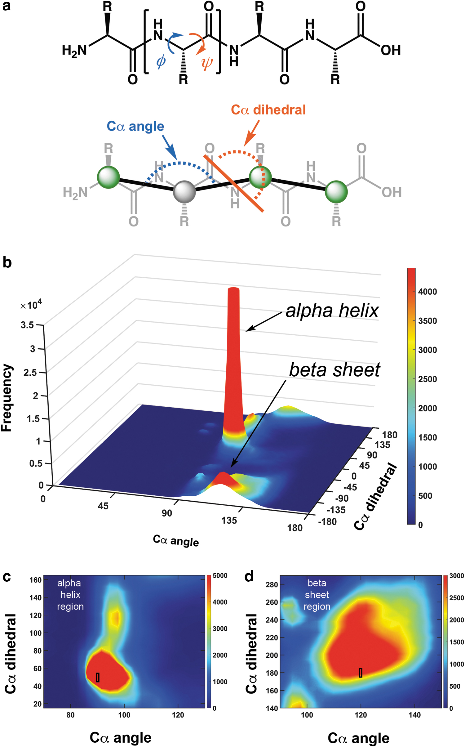
The alpha helix region of the plot clearly exhibits a sharp red spike, showing that there is a high frequency and low variation of angles adopted by alpha helices (Fig. 2b). Moreover, the beta sheet region of the plot also contains a spike, but it is comparatively broad (Fig. 2b). Thus, we can effectively represent the majority of protein secondary structures using angles within these narrow distributions. We therefore chose a representative pair of angles from the helix and sheet regions (black boxes in Fig. 2c, d) to construct secondary-structure-specific monomers (Fig. 3).
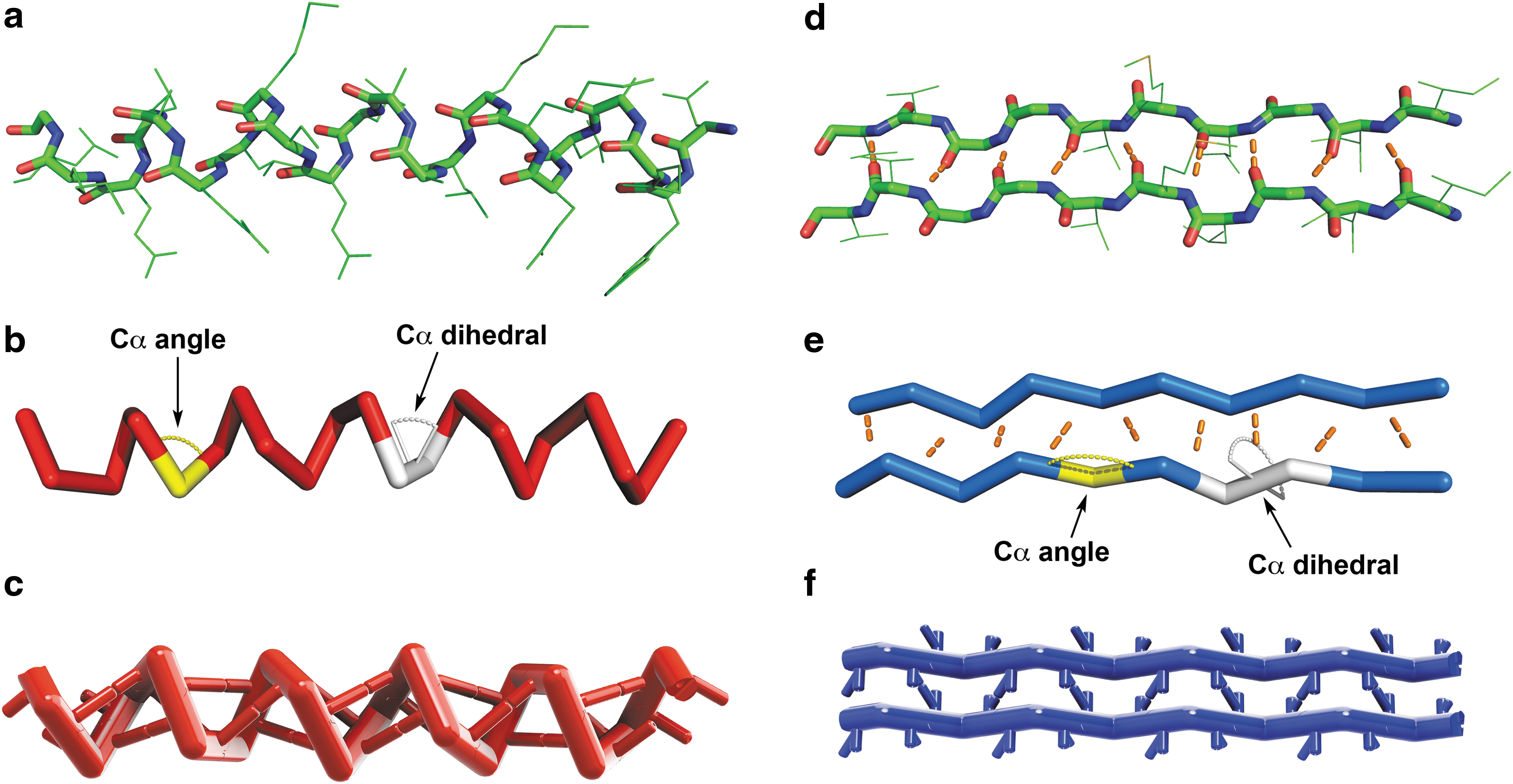
A segment of an alpha helix and beta sheet was extracted from a helical bundle protein (PBD: 1COS) and beta-amyloid protein (PBD: 2BEG), respectively. Here, the backbone of the alpha helix segment is shown in three different representations:
The Skeletide monomer pieces (Fig. 4) are designed to represent a single amino acid and consist of a single, central alpha carbon atom flanked by: (1) two connecting arms positioned at the Cα angle, (2) interconnects that bond with neighboring pieces to form the backbone according to the Cα dihedral angle, and (3) protrusions or poles to create long-range hydrogen bonding interactions. We designed the lengths of the arms by segmenting the distance between two alpha carbons in half. Thus, the actual lengths of the arms are arbitrary, but proportional to each other. The amino acid units connect to one another via a pair of inserted magnets (Fig. 4ii), allowing for the north and south poles of the magnets to control which ends of the piece can or cannot connect with the ends of another. When two pieces make a magnetic interconnect, the rotational orientation that the two pieces adopt relative to each other defines the Cα dihedral angle, which needs to be restricted to a small range of values. We therefore created a mechanical rotation barrier into these main chain interconnects that directs pieces to adopt a specific angle (±5°). This wiggle range is depicted by the rectangles labeled on the two-dimensional plot of each secondary structure (Fig. 2c, d). We call this linkage a Reversible Specific Angle Linkage or RSAL for short (Fig. 4ii). This RSAL is reversible due to the ability to link and unlink the magnets and enforces a specific interconnection angle range due to its wedge-shaped tongue and groove design. The wedge and its complementary slot are tapered to smoothly guide both pieces together as they approach one another.
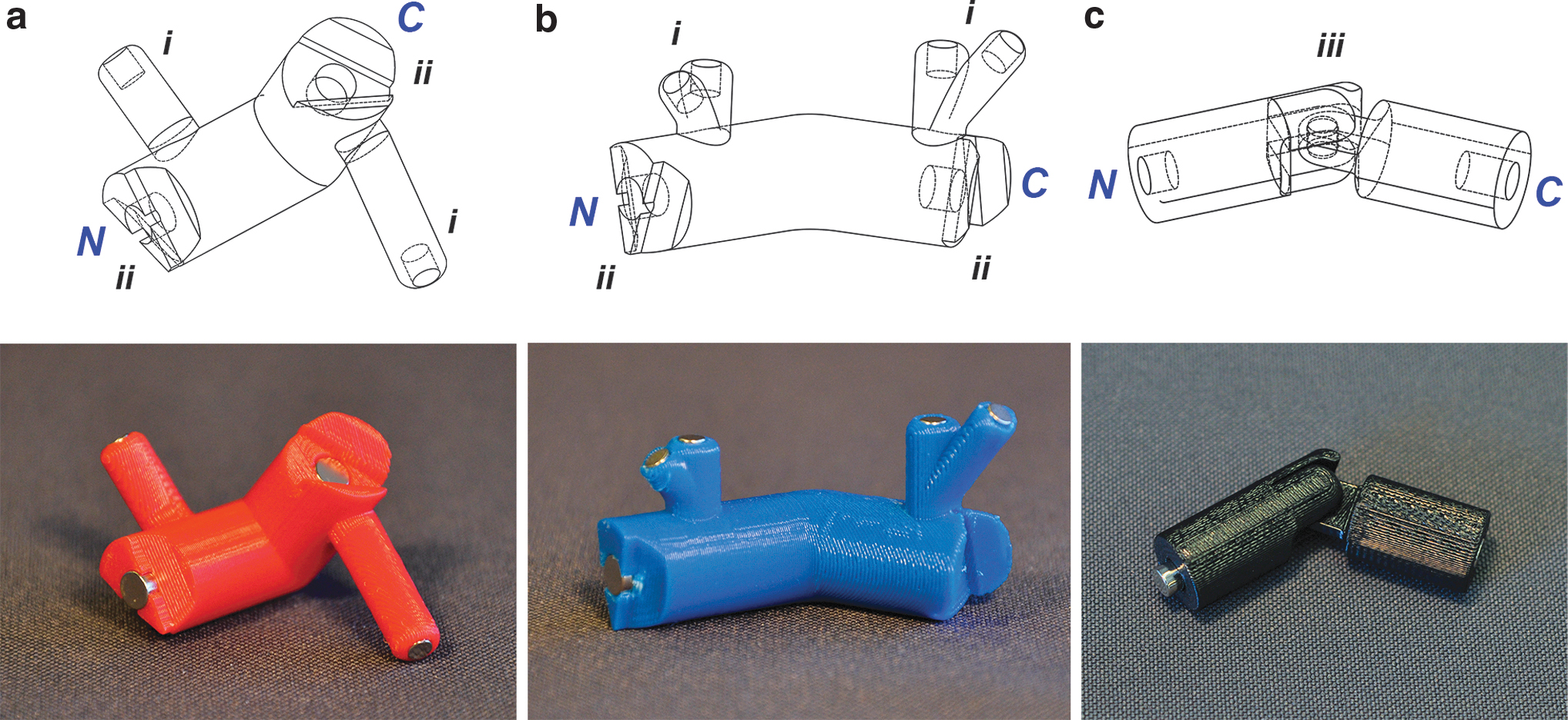
3D CAD drawings and 3D-printed physical models of the three Skeletide pieces:
To represent the hydrogen bonding (H-bonding) interactions of a secondary structure, we introduced two additional protrusions on each piece, one to represent the NH group (the H-bond donor) and the other to represent the carbonyl oxygen (the H-bond acceptor). We positioned smaller magnets at the tip of these protrusions (Fig. 4i). To position these poles, we drew a vector through the site of hydrogen bonding and arbitrarily set the anchor points on the arm surface of each piece. We then designed two poles from each of the anchor points that meet in the midpoint of the H-bonding vector (Fig. 4i). The pole that is attached on the N-terminal arm (the N-H group) was made longer, and the pole on the C-terminal arm (the oxygen) was made shorter, to represent the relative sizes of the atoms that contribute to the hydrogen bond. The differing magnet sizes between the RSAL and poles yield a pull strength ratio of roughly 2:1 (RSAL: 1.7 lbs and H-bond: 0.84 lbs), which crudely represents the relative strength between hydrogen bonds and covalent interactions. This design illustrates the hierarchical nature of protein structure, where once the pieces are linked together to form the backbone, the structure can be further stabilized by multiple weaker secondary (H-bond) interactions. CAD drawings indicating the key dimensions of each piece are provided in Supplementary Figure S1.
Alpha helix piece
To design the alpha helix amino acid monomer, we examined the centroid of the alpha helical region of the pseudo-Ramachandran plot (Fig. 2b). It has an alpha carbon angle of 90° and an alpha carbon dihedral angle of 50°, so we angled the arms and designed the wedge connections accordingly (Fig. 4a). We assigned the N-terminus of the piece to contain an extruded wedge and the C-terminus to be the recessed wedge (Fig. 4ii). We then constructed the H-bonding poles after the piece was assembled on the CAD software by drawing the vector from one of the arm surfaces to the same arm surface of another piece three residues ahead.
Beta sheet piece
Whereas alpha helices have one general hydrogen bonding pattern, beta sheets adopt two hydrogen bonding conformations, depending on the relative directionality of two adjacent strands. Because two beta sheet strands can be oriented either parallel or antiparallel, we sought to create one universal piece capable of forming either hydrogen bonding pattern. In each of these designed pieces, the centroid of the beta sheet region has an alpha carbon angle of 120° and a dihedral angle of −170°. However, because each beta sheet amino acid piece is identical to each other, using a −170° dihedral angle resulted in an asymmetrical linkage rotation, where the static nature of our hydrogen bonding pole design will not align as a result. Hence, we used a symmetrical 180° dihedral angle which is still contained within the inner circle of the beta sheet region of the pseudo-Ramachandran plot 23 (Fig. 2d). We assigned the N- and C-terminal features of the beta sheet pieces the same way as the alpha helix piece. Because beta sheets are defined by interchain hydrogen bonds, the distance between chains and the orientation of hydrogen bonding must be accounted for when designing the hydrogen bonding poles. To determine the length of the poles, the distance between the beta sheet strands was found by examining the PyMOL model of amyloid ABeta 1–42 (PDB ID: 2BEG), where we found the distance between two beta sheet strands to be 4.5 Å and the inter-alpha carbon distance to be 7.6 Å. As a result, we obtained a scaling factor of 6.9 mm/Å and thus calculated the distance between the beta sheets in our model to be 31 mm.
To enable the beta sheet monomer to form antiparallel and parallel strands, we designed two sets of hydrogen bonding poles originating from the same node to match closely with the nature of hydrogen bonding exhibited in each strand's respective molecular models (Fig. 4b). Using the interstrand distance of 31 mm, we constructed the hydrogen bonding pole length to match. We mimicked the roughly orthogonal pattern of the antiparallel beta sheets and the diagonal pattern of the parallel beta sheets.
Turn piece
Finally, the turn piece needs to be able to adopt a variety of conformations since protein turns have a broad diversity of geometries. We therefore designed this piece to be the exact size of a single amino acid but exhibit much less conformational constraint in both the Cα angle and the Cα dihedral angle. By examination of the pseudo-Ramachandran plot (Fig. 2b), we observe that the landscape of allowed conformations is bounded by a Cα angle that ranges between 80° and 150° and a Cα dihedral angle that can freely rotate anywhere between −180° and 180°. To account for this broad but limited range of potential Cα angles for the turn piece, a hinge design was implemented, which allows the two arms to dynamically traverse between 80° and 150° (Fig. 4iii). To allow for full rotation of the Cα dihedral angle, we omitted the wedge interconnect from the RSAL design. We designed the N-terminal magnet to protrude out from its housing to be able to reach the recessed magnet on an RSAL C-terminus on the other pieces (Fig. 4c). The resulting linkages can thus freely rotate its dihedral angle (in either the N- or C-direction). Turns are not a repetitive element in secondary structures and do not contain a consistent and specific conformation that can be effectively represented by our static hydrogen bonding poles, so hydrogen bonds were omitted from our design. This model therefore faithfully represents the prominent secondary structural elements and uses turn pieces to bridge between them (Fig. 1d).
Spontaneous assembly of secondary structures
We observed that the Skeletide pieces exhibited a propensity to spontaneously assemble into their corresponding secondary structures. To demonstrate this property, we studied their behavior upon the agitation of many pieces together in a container. 25 While this property nicely illustrates the modularity of protein structure—that a single structural unit can be linked together to form a larger, regular secondary structure—it does not accurately mimic the protein folding process in biology. To facilitate the self-assembly design, we created a special class of Skeletide models with weaker magnets and observed their collective behavior by letting them interact via random collision in a circulating water tank (Fig. 5). The RSAL magnet pull strength was reduced from 1.7 to 0.84 lbs, whereas the hydrogen bonding magnet was reduced from 0.84 to 0.12 lbs. A stronger linkage is desirable when handling the model by hand, but when floating in water, we found that a weaker linkage is required. The agitation of water was enabled with a submersible pump, which recycled water within the tank. The buoyancy in water reduces the effect of gravity, so weaker magnets can be used to hold them together. In fact, if strong magnets are used in the assembly tank, nonspecific interactions become too difficult to break apart, leading to the formation of unwanted aggregated structures (Supplementary Fig. S3). We therefore reduced the pull strength of both magnet types for the self-assembly version of the pieces (Supplementary Data) and adjusted the overall density of the pieces to be slightly higher than water.
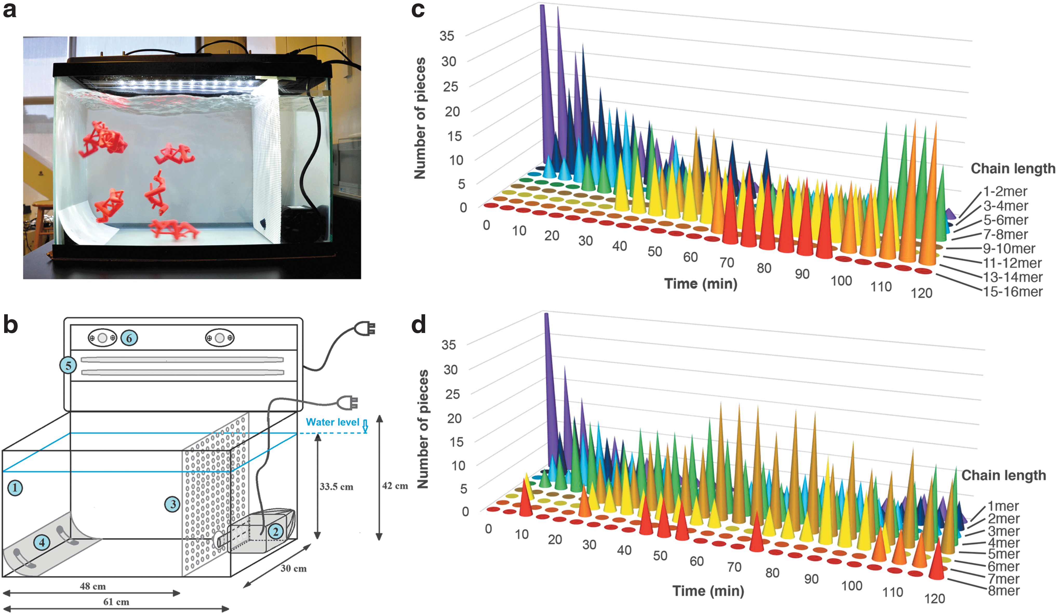
Self-assembly trials were performed with 50 identical (alpha helix or beta sheet) pieces in a volume of ∼50 L, which represents a molar concentration of ∼2 mM. The pieces were agitated for a total of 2 h, and photos were captured every 1 min to follow the assembly progress (see Supplementary Videos S1 and S2 for assembly trials of the helix and sheet pieces, respectively). The self-assembly behavior was analyzed by visual inspection of the assembly photos (Fig. 5, Supplementary Figs. S4 and S5). In both cases, the desired secondary structures successfully formed. The assembly process was dynamic, with many bonds (some correct and some incorrect) forming and breaking over time. The nonspecific bonds (i.e., incorrect magnet interactions) quickly formed at the start of the process, and then gradually diminished over time, whereas the number of correct interactions increased (Supplementary Fig. S6). This effect was considerably stronger for the alpha helix pieces, which converge to an assembled state much faster (Supplementary Fig. S7). We further observed that the beta sheets, where H-bonds form between two different strands, are structurally weaker than the alpha helices, where the H-bonds form within a single strand. Thus, the beta sheets that form tended to break apart eventually, whereas the helices persisted. The alpha helices tended to grow by the addition of single monomers to the termini, whereas beta sheets tended to form only by the association of two already formed strands. Over time, the average length of alpha helices gradually increased, whereas the average length of beta sheets, together with the space constraint, reached approximately half of that of the alpha helices (Supplementary Fig. S8). In the case of the beta sheets, both parallel and antiparallel structures formed.
Conclusion
There is an unmet need for simple models that can represent the most basic skeletal structure of proteins. The underlying geometry of protein secondary structure is very highly conserved, allowing us to create a small but universal set of three pieces that can be combined to build nearly any protein backbone of interest. Models such as these can aid biomedical researchers and serve as educational tools for students and the general public to more intuitively understand how Nature creates structure by folding linear chains into precise 3D architectures.
We have shown that we can represent protein secondary structure using a simple set of only three pre-organized pieces. These pieces can be readily made using a 3D printer and assembled with little or no tools. The pieces can readily create helix and sheet secondary structures (Supplementary Fig. S9), and these elements can be combined to form tertiary structures, such as a protein zinc-finger domain, suggesting that simplified models such as this could be used to readily assemble a variety of proteins.
The spontaneous self-assembly of individual pieces into higher order alpha helix or beta sheet secondary structures was successfully observed over a 2-h course when incubated in a circulating water chamber. Being an intrinsically stable structure, the alpha helix self-assembly process happened rapidly within the first hour and generated several long alpha helices that persisted. Beta sheet assembly was slower and the structures more dynamic, due to the lower stability of the sheet (which requires two strands to come together held only by the H-bonds). This spontaneous assembly study illustrates the modularity of protein secondary structure, and how protein structure arises from multiple identical pieces working cooperatively through a network of weak interactions.
The Skeletide model developed here underlines the most fundamental aspects of protein secondary structure by depicting: (1) the skeletal alpha carbon trace and (2) an accurate representation of long-range intra-main chain H-bonding interactions. To focus on these model elements, we made inherent simplifications with regard to degrees of rotational freedom and side chain incorporation. We envision future versions of this model to include attachable side chains that interact with each other and to further tune the relative strengths of interconnects. Additionally, more dynamic pieces could be designed to exhibit a wider range of angles in the pseudo-Ramachandran plot (Fig. 2). Further development and improvement upon the Skeletide model will open greater avenues of protein exploration. Future studies into similar self-assembling models may help to reveal even more about the complex cooperative interactions that bridge biological structure and function.
Footnotes
Acknowledgments
The authors thank Michael Connolly and Bryanna Benicia for helpful discussions.
Author Disclosure Statement
No competing financial interests exist.
Funding Information
Work at the Molecular Foundry was supported by the Office of Science, Office of Basic Energy Sciences, of the U.S. Department of Energy under Contract No. DE-AC02-05CH11231.
References
Supplementary Material
Please find the following supplemental material available below.
For Open Access articles published under a Creative Commons License, all supplemental material carries the same license as the article it is associated with.
For non-Open Access articles published, all supplemental material carries a non-exclusive license, and permission requests for re-use of supplemental material or any part of supplemental material shall be sent directly to the copyright owner as specified in the copyright notice associated with the article.