
Abstract
Abstract
Selective laser melting (SLM) is one methodology to realize additive manufacturing and is mainly used to join metal powder in a layer-by-layer manner to produce a solid three-dimensional (3D) object. For bone tissue engineering purposes, scaffolds can readily be designed as 3D data model and realized with titanium known for its excellent osseointegration behavior. The microarchitecture, that is, design with submillimeter features, of additively manufactured scaffolds is in many cases a lattice structure. This study aimed to apply SLM that allows a high degree of microarchitectural freedom to generate lattice structures and to determine the optimal distance between rods and the optimal diameter of rods for osteoconduction (bone ingrowth into scaffolds) and bone regeneration. For the biological readout, diverse SLM-fabricated titanium implants were placed in the calvarium of rabbits and new bone formation and defect bridging were determined after 4 weeks of healing. The results from the middle section of the defects show that with a lattice microarchitecture, the optimal distance between titanium rods is around 0.8 mm and the optimal rod dimension is between 0.3 and 0.4 mm to optimize defect bridging and bone regeneration.
Introduction
Bone replacement materials need to be accepted by the body and should clinically be infiltrated with bone tissue within a short time, so ideally they are osteoconductive. Bone tissue engineering of osteoconductive biomaterials like other tissue engineering approaches normally relies on the combination of cells, bioactive factors, and biomaterial scaffold to facilitate and accelerate the regeneration of bone tissue.1,2 The macroarchitecture defined as the millimeter-to-centimeter-sized outer shape of the scaffold is in most cases identical to the dimensions of the bone defect and, therefore, patient specific. It can be realized by several different approaches such as in situ forming implants 3 or in situ forming hydrogels.4, 5 If mechanically more stable personalized bone tissue scaffolds are mandatory, additive manufacturing (AM) provides the tools to produce patient-specific implants from a variety of materials including calcium phosphates and titanium.6,7
For personalized bone substitutes, the AM process could be based on converted computer tomography data from the patients or any other three-dimensional (3D) model data set. 8 The process itself makes the scaffold layer upon layer, dependent on the material used by diverse methodologies, including stereolithography, selective laser sintering, three-dimensional printing (3DP), and fused deposition modeling. 9 In stereolithography, ultraviolet light or laser polymerizes defined areas of individual layers to form an object from layers of photosensitive polymers. This technique was already established in 1981. 10 In 1989, selective laser sintering was developed and patented 11 wherein a high-intensity laser beam is used to build an object in a metal, polymer, ceramic, or hybrid powder bed. In 3DP, developed in 1990 at the Massachusetts Institute of Technology, the object forms in a powder bed by the deposition of a liquid binder material using inkjet heads. 12 One of the first studies with 3D-printed hydroxyapatite scaffolds showed deep cell proliferation into structures with dimensions and pore sizes of about 500 μm. 13 Melt-extrusion AM was established in 1992 14 and solution/slurry extrusion in 2002.15,16 In both cases, a polymeric filament is extruded through a nozzle and deposited layer-by-layer on a building platform. If applied for bone tissue engineering, extrusion-based AM mainly produces lattice structures as submillimeter-sized microarchitecture of the newly formed bone substitute, wherein the thickness of the deposited filament defines the minimal structure dimension. Fused deposition modeling was first explored with poly-ɛ-caprolactone (PCL) and PCL-hydroxyapatite composites by Hutmacher et al. 17 and applied in humans to cover cranial defects. 18 More recently, extrusion was also used to produce scaffolds from bioglass to generate grid-like structures for the treatment of large cranial defects. 19
The ideal microstructure of a bone tissue engineering construct was defined in the 1990s, when porous ceramic-based bone substitutes were produced mainly with porogens, following a space-holder methodology. At that time, it was established that the pores in a bone tissue engineering scaffold are ideally between 0.3 and 0.5 mm in diameter.20–22 More recent work by others on porogen-based porous bone substitutes 23 and us on additively manufactured open porous scaffolds24,25 showed that bone tissue engineering scaffolds with pores exceeding 500 μm are efficient for bone ingrowth and bone regeneration in vivo.
Dependent on the methodology and the materials, AM can be used to realize a wide variety of microstructures including also functionally graded scaffolds. 26 Not only the macro- and microporosity of PCL scaffolds produced by a 3D plotting technique 27 but also the macroscopic arrangement of the porous arrangement in ceramic scaffolds is important. 28 As known from regenerative therapies by tissue engineering, the ideal pore size of scaffolds made of ceramics, synthetic polymers, and natural polymers also depends on the applied cell type,29,30 in particular when studying on the molecular level 31 or in vitro. 32
Titanium and titanium alloys are suitable materials for bone substitutes, since they exhibit a high specific strength and support osteoblast colonization and differentiation into mature bone cells. 33 Possible applications of additively manufactured titanium implants in craniomaxillofacial surgery (reviewed in Ref. 34 ) range from personalized titanium implants for the reconstruction of the orbital floor, 35 the ramus mandibulae, and the condyle 36 to dental implants. 37 In orthopedics, additively manufactured titanium constructs proved useful for long-bone defects.38,39 By AM, a mechanobiologically optimized 3D titanium-mesh structure could be realized to promote the healing of a critical-size long-bone defect in sheep by a design that reduced stress shielding. 39 Ti-6Al-4V-based personalized plates were used successfully to treat complex pelvic fractures. 40 In vitro experiments indicate that trabecular bone-like 3D structures produced by selective laser melting (SLM) of Ti-6Al-4V favor osteogenesis, especially at high porosity. 41 Honey-comb structures with effective pore diameter from 0.2 to 0.7 mm produced by the same material through direct laser forming showed good cell compatibility. 42 The same applies to a rapid prototyped porous nickel–titanium scaffold. 43 A more extended study on pore geometry and its effect on human periosteum-derived cells was performed with diverse selective laser-melted Ti-6Al-4V bone scaffolds to show that cell proliferation depends on pore size but not on pore shape. Differentiation, however, depends on both parameters. 44
Despite all these in vitro and in vivo studies, the knowledge about the effect of diverse lattice microarchitectures on the in vivo ingrowth velocity of bone tissue into the scaffold and bone formation is limited. Therefore, we used SLM of titanium 45 to produce lattice implants of systematically varied rod distances (four different porous channel widths w between 300 and 1800 μm) and rod calibers (five different calibers s between 200 to 1500 μm) to study the influence of those microarchitectural parameters on bone regeneration and defect bridging in a calvarial defect model system in rabbits in great detail.
Materials and Methods
Implant design
The implants were constructed with Solidworks CAD system (Solidworks V.2013 Software, www.solidworks.com, Dassault Systèmes, France). The outer macrogeometry of the implants is designed as stepped cylinders of 7.5 mm, respectively, 6 mm diameter and a height of 4.2 mm. The inner microarchitecture is constructed by cutting out symmetrically arranged square channels in all three orthogonal directions, see Figure 1. Based on most promising scaffold parameters from the literature, 29 the width of the channels w (distance between the rods) and the wall thickness s (rod caliber) of the remaining trusses have been systematically varied in a way that complete layers of cubic unit cells are formed along the cylindrical main axis (see Fig. 1 for an overview of the designs and Table 1 for the structural values). Finally, a 0.2 mm fine ring completes the outermost margin of the framework to close the last layer and prevent sharp edges during surgery. Three series of implant design have been constructed:
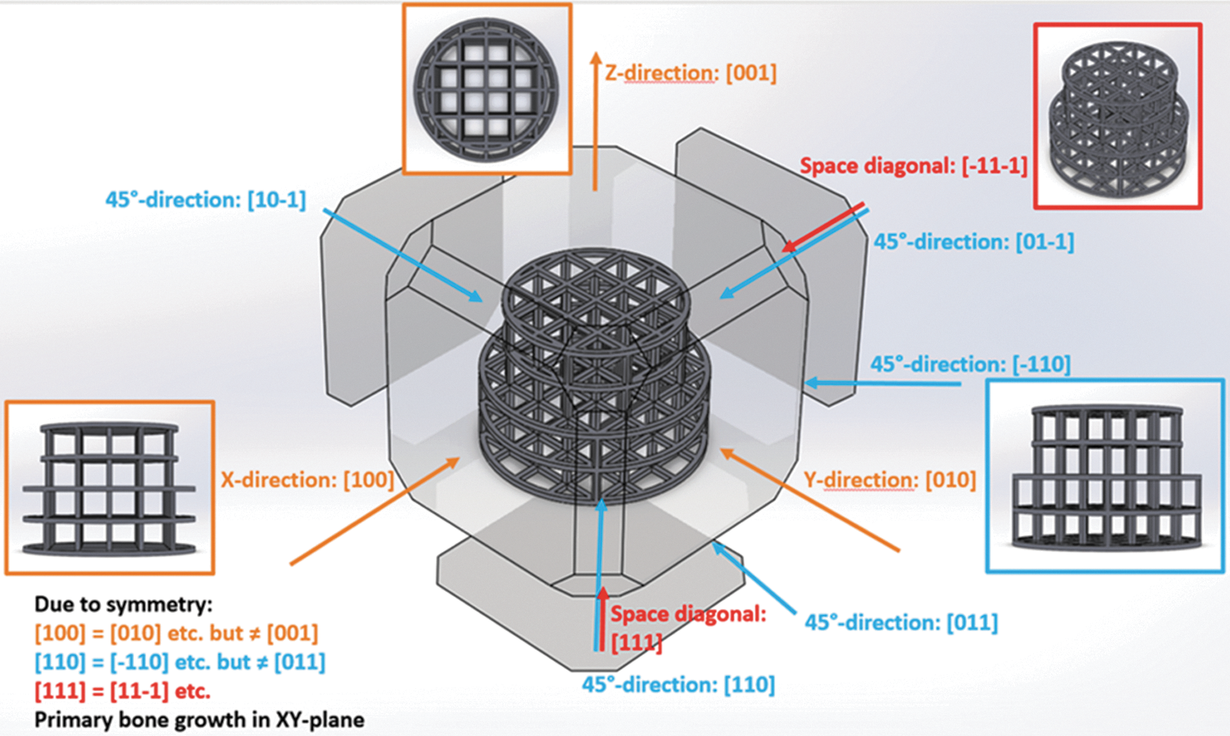
Design of the tested implants. The different profile views used for characterization are shown.
Structural Values of the Three Designed Series of Scaffolds with Engineered Orthogonal Lattice Geometry
Transp, transparency.
(1) First series with constant rod calibers s of 0.2 mm, but with varied channel width w, that is, distance between the rods of 0.3, 0.466, 0.8, and 1.8 mm.
(2) Second series with fixed channel width w of 0.5 mm, however, with different rod calibers s of 0.2, 0.5, and 1.5 mm.
(3) Third series with fixed channel width w of 0.8 mm, however, with different rod calibers s of 0.2, 0.3, and 0.4 mm.
These geometrical values are determined to guarantee a total height of the scaffold of exact 4.2 mm for series 1 and 2 and uniformly distributed channels and rods with biologically meaningful profiles. To compare the individual scaffolds, their theoretical characteristics were calculated. The most important being (Table 1) the following:
• The relative free volume (Vfree) describing the ratio of the free volume inside the scaffold (Venclosed). • The relative transparencies (relative free area in the projection of the scaffold in the different spatial directions, as shown in Fig. 1). • The total scaffold surface, which is significant for the corrosion process.
Implant production
The implants were produced by the Realizer 250HT selective laser melting system (SLM Solutions, Lübeck, Germany). Under a protective argon gas atmosphere, titanium powder grade 2 (supplier: Realizer GmbH, Borchen, Germany) of average particle size of 60 μm was evenly spread onto a titanium building platform after the platform has been lowered by 30 μm. A 200 W infrared laser then scanned over that powder bed. By the focused laser energy, the irradiated Ti particles fused with the underlying layer along the trajectories of the laser. This process was repeated layer-by-layer until the structures were completely produced. When the building platform and the implants had cooled down, they were removed from the building chamber and the implants were carefully detached from the underlying support structures, respectively, from the platform. As described in Ref., 24 ultrasonic, chemical, and plasma cleaning procedures followed before the scaffolds were packed into a peel bag and gamma sterilized at 25 kGy.
The effective strut diameter s, the channel width w, and the surface morphology of the produced implants were determined by scanning electron microscopy (Hitachi TM3030, Japan, 15 kV, BSE detector). The overall geometry was examined by vernier caliper (TESA Cal IP 67, TESA, Switzerland).
Surgical procedure
All animal experiments comply with the Animal Research: Reporting of In Vivo Experiments guidelines and were carried out in accordance with the EU Directive 2010/63/EU for animal experiments. Eighteen adult (12 months old) New Zealand White rabbits were used in this study. The animals' weight was between 3.5 and 4.0 kg and they were fed a standard laboratory diet. Animals were housed in groups of 2–4 and allocated to the four scaffolds applied per animal at random. The procedure was evaluated and accepted by the local authorities (108/2012 and 115/2015). To initiate the operation, the animals were anesthetized by an injection of 65 mg/kg ketamine and 4 mg/kg xylazine and maintained under anesthesia with isoflurane/O2. After disinfection, an incision from the nasal bone to the midsagittal crest was made, the soft tissue deflected, and the periosteum removed. Next, four evenly distributed 6-mm-diameter craniotomy defects were prepared with a trephine bur under copious irrigation with sterile saline in the operation field. Then, all defects were completed with a rose burr (1 mm) to preserve the dura. Next, all the defects were flushed with saline to remove remaining debris and the implants were applied by press fitting. Each of the animals received four different treatment modalities. The treatment modalities were assigned at random for the first animal, and thereafter, cyclic permuted clockwise. The treatments were grouped for distance of rods and rod thickness. Each scaffold type was applied six times. After the completion of implant placement, the soft tissues were closed with interrupted sutures. Four weeks after operation, the rabbits were placed under general anesthesia and sacrificed by an overdose of pentobarbital. The cranium containing all four craniotomy sites was removed and placed in 40% ethanol.
Embedding
Embedding was performed as previously reported. 24 In short, the specimens were prepared with a sequential water substitution process. It involved 48 h in 40% ethanol, 72 h in 70% ethanol (changed every 24 h), 72 h in 96% ethanol, and finally, 72 h in 100% ethanol. Thereafter, samples were placed in xylene for 72 h (changed every 24 h) followed by methyl methacrylate (MMA) for 72 h (Fluka 64200) and 100 mL MMA +2 g dibenzoylperoxid (Fluka 38581) at 4°C for 4 days. For polymerization, samples were submerged in 100 mL MMA +3 g dibenzoylperoxid +10 mL plastoid N or dibutylphthalate (Merck 800 19.25) at 37°C in an incubator. After embedding, the skull was cut into four pieces each containing one craniotomy site by using an EXAKT 300P saw (Exakt, Norderstedt, Germany). The samples were sectioned through the middle of the defect. Sections of 200 mm thickness were obtained, ground, and polished to a uniform thickness of 60–80 mm. The specimens were surface stained with toluidine blue. 46
Histomorphometry
Evaluation of all implants was performed from the middle section using image analysis software (Image-Pro Plus®; Media Cybernetic, Silver Springs, MD). The area of interest (AOI) was defined by the 6 mm defect dimension and the height of the implant. Corrections were made for differences in implant height in series 3. We determined the area of new bone in the AOI as percentage of bone and bony integrated scaffold in the AOI (bony area, %). For the empty control value, the average area occupied by the titanium implants of all designs was taken into account.
Bone bridging
The determination of bone bridging was performed as reported earlier.47,48 In brief, areas with bone tissue were projected onto the x-axis. Next, the stretches of the x-axis where bone formation had occurred at any level were summed up and related to the defect width of 6 mm. Bone bridging is given in percentage of the defect width (6 mm) where bone formation had occurred.
Statistical analysis
The primary analysis unit was the animal. For all parameters tested, the treatment modalities were compared with a Kruskal–Wallis test, followed by pairwise comparison of treatment modalities with the Mann–Whitney test for dependent data (IBM SPSS v.19). p values are displayed in the graphs and significance was set at a limit of p < 0.05. Data from 18 rabbits are presented. Values are reported as mean ± standard deviation.
Results
Implant design and surface morphology
The geometry of the final implants was verified microscopically and metrologically. The rod calibers s and the channel width w were determined in scanning electron images, whereas the total height and the diameters of the inner and outer cylindrical sections were determined by tactile gauge (n = 3). The lattice design and symmetry were absolutely reproduced in the physical scaffolds. Although the outer geometry of the additively manufactured implants (htot, øsmall and øbig) exactly corresponds to the designed geometry (see Table 1), the rod calibers s trend to slightly oversize 5.9% in standard error of mean measurements in the top view and 12.8% in lateral view. This geometrical deviation mainly derives from powder particles that are sintered to the surface of the struts. The surface morphology, typical for SLM surfaces, shows an extensive decoration with fused titanium particles, which explains the increased strut size s. Consequently, the channel width w of the as-printed structures tends to be reduced compared with the designed values: 1.2% in top view and 5.6% in lateral view.
Titanium grid structures and bone regeneration
All animals stayed in good health and in the ground sections, no signs of inflammation could be detected. Bone formation occurred close to and in contact with the bone substitutes irrespective of the designs used (Fig. 2), which indicates a good overall biocompatibility of all designs in all series.
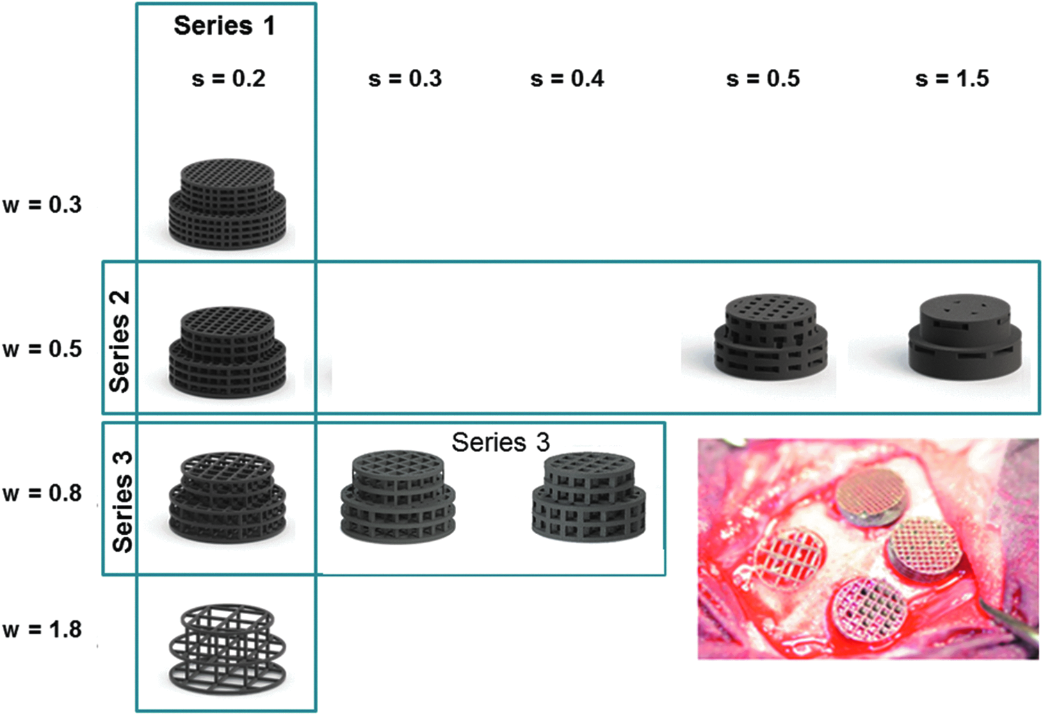
Titanium grid designs. In a first series, different distances between rods were tested at a fixed rod caliber of 0.2 mm. An intraoperative picture of the four designs after placement is provided in the right lower corner. The distances between the rods increased from 0.3 to 1.8 mm. In the second series, different calibers of rods were tested ranging from 0.2 to 1.5 mm at a fixed rod distance of 0.5 mm. In the third series, different calibers of rods were tested ranging from 0.2 to 0.4 mm at a fixed rod distance of 0.8 mm.
Rod distance in grid structures and bone regeneration
In the first set of experiments, rod distances w in the lattice structure were tested at a fixed rod caliber of s = 0.2 mm. The histological sections (Fig. 3) revealed that based on the middle sections, the microarchitecture variations in the distance between rods w had a pronounced effect on bony regeneration of the defect. First, we determined bony regeneration of the defect in the middle sections. Here we found a significant relationship between rod distance w and bone regeneration (Fig. 4a). At a rod distance of w = 0.3 and 0.5 mm, the percentage of bony regenerated area was 30.36% ± 7.94% and 31.86% ± 6.88%, respectively. At a rod distance of w = 0.8 mm, bony regenerated area was 51.98% ± 13.10% and significantly higher than for the 0.5 mm distance (p = 0.005) and for the distance of w = 1.8 mm (p = 0.026). The percentage of bony regenerated area of the latter was 38.51 ± 3.37, and for the empty defect with an assumptive rod distance of w = 6 mm corresponding to the defect dimension, it was 14.75% ± 5.25%. For all implants with a rod distance between w = 0.3 and 1.8 mm, bony regenerated area was significantly higher (p = 0.003) than with the empty defect with an assumed rod distance of w = 6 mm.
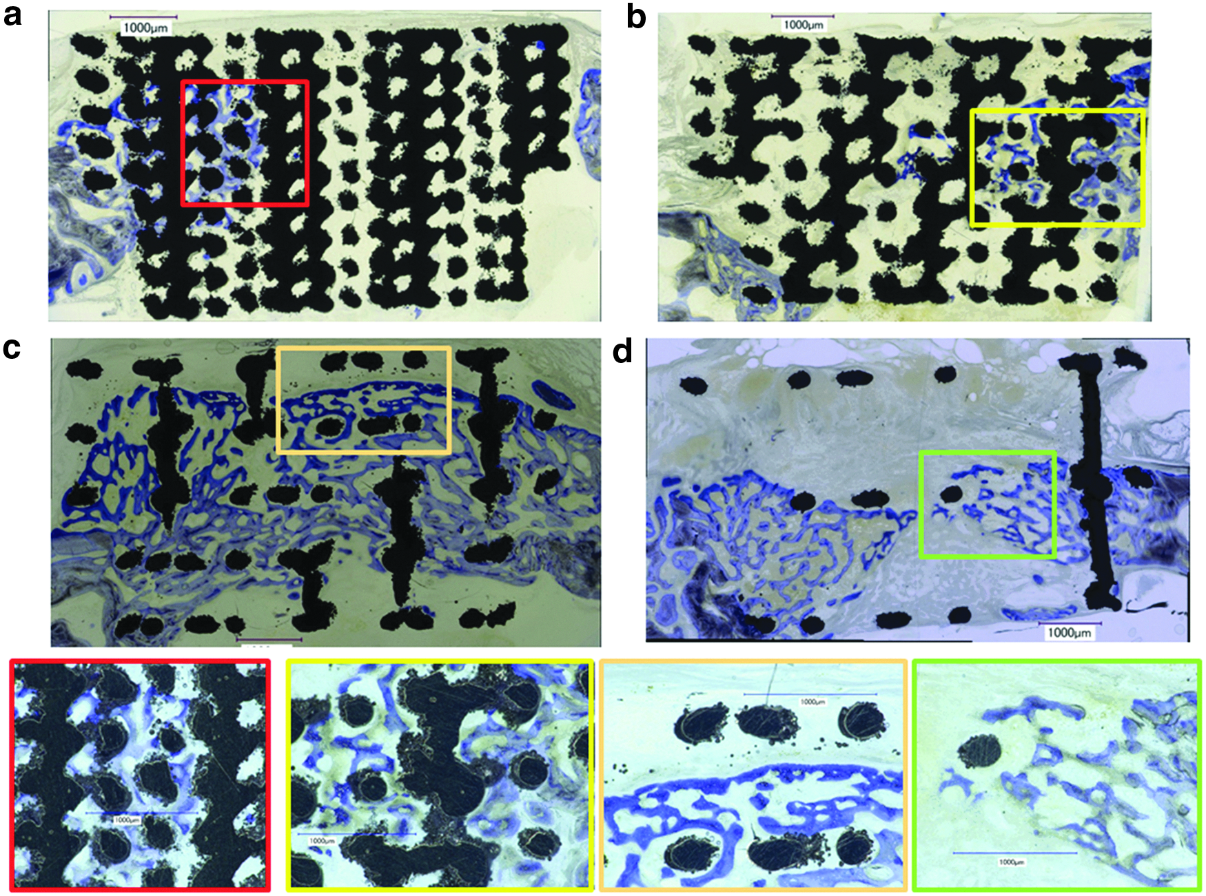
Histological sections from the middle of the defect of series 1 at a fixed rod caliber of s = 0.2 mm and varying rod distances w.
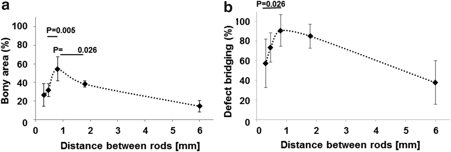
Bone histomorphometric parameters in the AOI as a function of the rod distance w in scaffolds with a constant rod caliber s = 0.2 mm from series 1.
In this set of experiment, bony bridging was 57.50% ± 24.57% for rod distance of w = 0.3 mm, 73.57% ± 14.82% for rod distance of w = 0.5 mm, 90.83% ± 16.22% for rod distance of w = 0.8 mm, and 85.27% ± 12.17% for a rod distance of w = 1.8 mm (Fig. 3b). A significant difference could be detected between rod distances of w = 0.3 and 0.8 mm. The empty defect with an assumed rod distance of w = 6 mm, however, showed bony bridging to 37.77% ± 22.20% and was significantly lower than all other groups in series 1 (p = 0.005).
Rod dimension and bone regeneration
In the series 2, we compared bone regeneration at a fixed rod distance of 0.5 mm for rod calibers of 0.2, 0.5, and 1.5 mm but no significant difference could be detected between the implant groups based on bony regenerated area or defect bridging. Therefore, in the third series of experiments, we applied the aforementioned results about the optimal rod distance to be w = 0.8 mm and designed and produced grids with a constant distance between rods of w = 0.8 mm and varied the caliber of the rods from s = 0.2 to 0.4 mm. We failed to build an implant with a rod caliber of s = 0.1 mm due to procedural limitations of our manufacturing system. The histological sections (Fig. 5) revealed that based on the middle sections, the microarchitecture variations in rods caliber s affected bony regeneration of the defect.
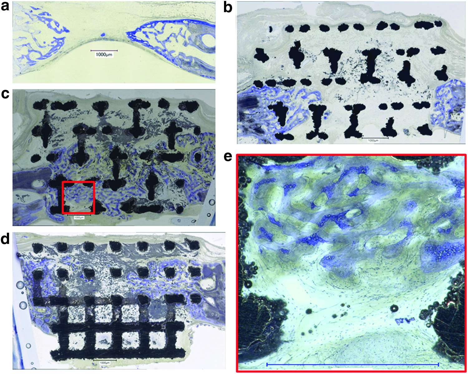
Histological sections from the middle of the defect of series 3 at a fixed rod distance of w = 0.8 mm as a function of the rod caliber s.
At a rod distance of 0.8 mm, bone regeneration appeared to be significantly dependent on the rod calibers in the range of 0.2 to 0.4 mm (Fig. 6a). At a rod caliber of s = 0.2 mm, percentage of bony regenerated area was 44.51% ± 14.26%. At a rod caliber of s = 0.3 mm, bony regenerated area was 64.64% ± 11.57% and significantly higher than for the s = 0.2 mm caliber (p = 0.035). No significant difference to 0.2 and 0.3 mm rod calibers s was detected in comparison with the rod caliber of 0.4 mm. The percentage of bony regenerated area of the latter was 57.63 ± 11.73, and for the empty defect it was 14.75% ± 5.25%. For all implants with a rod calibers between s = 0.2 to 0.4 mm, bony regenerated area was significantly higher (p = 0.003) than in empty defects with an assumed rod caliber of 0 mm.
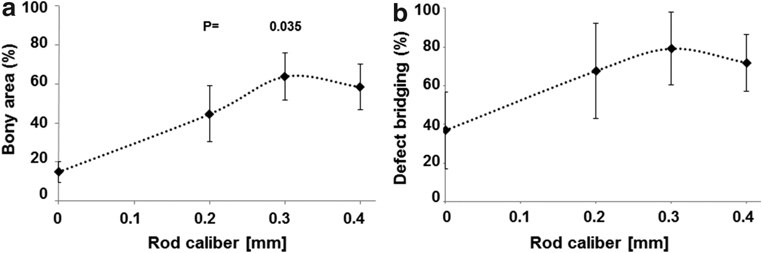
Bony regeneration in the AOI of scaffolds with rod distances w = 0.8 mm and different rod calibers s.
In this set of experiments, bony bridging was 67.62% ± 24.50% for rod caliber of r = 0.2 mm, 79.616% ± 18.15% for rod caliber of r = 0.3 mm, and 71.90% ± 14.66% for a rod caliber of r = 0.4 mm (Fig. 6b). No significant difference could be detected with calibers between 0.2 and 0.4 mm. The empty defect with an assumed rod caliber of 0 mm, however, showed bony bridging to 36.85% ± 19.69% and was significantly lower than all other groups (p = 0.003).
Discussion
SLM implant designs
In previous studies, the influence of the surface morphology 24 and several microarchitectures 25 were investigated. Here, the lattice symmetry, surface morphology, the scaffolds bulk material, and the surface chemistry were kept constant while only lateral geometric parameters were varied: the strut calibers s and the channel width w or distance between the rods were adapted to study their effects on bone regeneration properties in vivo.
Biological effects
Lattice structures are often used as basic design principle for the microarchitecture of bone substitute scaffolds.26,49–51 Rod dimensions and distance between rods are in most cases selected based on mechanical needs to match them to bone 51 or due to mechanical restrictions by the production process, for example, the mechanics of the extruded filament.19,52 Here we used titanium, known for its excellent osseointegration potential and AM by SLM to provide a high degree of design freedom to study bone regeneration in lattice structures in vivo dependent solely on the strut dimensions and the distance between struts. Our results show that bone regeneration and bony bridging facilitated by a titanium lattice structure are significantly improved when the distance between the rods is around 0.8 mm (Fig. 4) and the rod diameter is 0.3 mm (Fig. 6). Whereas the absolute thickness of the rods s plays a minor role, the width w between the struts appears as the most crucial factor.
Twenty years ago, the optimal pore size for bone tissue engineering was found to be between 0.3 and 0.5 mm20–22 and almost all porous bone substitutes up to now 53 are designed accordingly. Based on our results on the distance between struts, the optimal pore matching this lattice would have a theoretical diameter of 0.89 mm and would be much bigger than previously proposed. That the optimal pore size in bone substitute exceeds 0.5 mm in diameter has recently been suggested by other researchers 23 and us. 25 Here we report on the optimal strut distance and strut caliber of lattice architectures.
Production-related limitations such as the averaged powder particle size of 60 μm, the laser focus of several tens of micrometers, and the powder layer height of 30 μm lead to minimal, however, reproducible channel size w of 0.3 mm. Moreover, the size of the noncritical defect of 6 mm and the thickness of the calvarial bone of 2.8 to 3.5 mm are additional limitations of this study. Our results, however, show that strut distances of 0.5 and 1.8 mm are significantly less effective for bone regeneration than 0.8 mm, and these structures are well within the inherent limitations of this model. From our previous work, 25 we know that openings of up to 1.3 mm perform well in this model. That sets the optimal rod distances in a lattice structure from titanium to 0.8 mm and thus about two times further apart than the dogma for optimal porosity of bone substitutes suggests. 32 Lattice structures with these characteristics can be produced by several AM methodologies and from diverse materials. However, further studies are needed to study the material dependency of the optimized microarchitecture in more detail.
Bone substitutes materials, even if they are osteoconductive, can support or hinder defect bridging. 54 That is particularly true when open porous bone substitutes are compared with granular bone substitutes. 55 Fast defect bridging appears to be facilitated by interconnected channels and lack of bottlenecks achieved perfectly by lattice microarchitectures. However, a minimum density of struts or an optimal distance between struts is needed, otherwise bony healing at low strut density (Fig. 3d) resembles bony healing in empty defects (Fig. 5a). Therefore, the struts at the optimal density provide the guiding cue to direct bone formation toward defect bridging, which is the initial goal of bone regeneration, since the major problems in bone regeneration are persistent delayed- or nonunions. 56
Conclusions
In this systematic approach, identical bulk material, surface chemistry, surface topography, macrodesign, and lattice symmetry were used to study the influences of rod distance and rod caliber in a lattice titanium microarchitecture designed for bone regeneration purposes. The results show that significantly better results are achieved at a rod distance of 0.8 mm and a rod caliber of 0.3–0.4 mm. Since AM and 3DP in many cases yield in a lattice microarchitecture, these results suggest to overcome the former dogma on channels of 0.3 to 0.5 mm and substitute them by channels of 0.8 mm for bone substitutes, where bone ingrowth has to occur fast and efficiently.
Footnotes
Acknowledgments
The authors thank Ana Perez and Alexandr Tchouboukov for excellent technical work and Thea Fleischmann for her support on the animal experiments. This research work was supported by grants from the Swiss National Science Foundation to F.E.W.
Author Disclosure Statement
No competing financial interests exist.