
Abstract
Abstract
The challenges associated with ceramic stereolithography using high solid loading suspensions are related to the formation of ultrathin layers with high-viscosity suspensions and uneven green bodies, deriving from sedimentation problems. Furthermore, for a bottom-up projection system, the separating force must be focused. The digital light process system and bottom-up projection method have been used in this current work to create a ceramic green part. Our special design of a coating–storing–stirring recoating system tackles the problems relating to both ultrathin layers and sedimentation and it can also store the suspension to make the process more convenient. A stretch elastic separating film that diminishes the separating force and effectively reduces printing defects has also been designed. The strain forces in the improved coating process and stripping process were also analyzed. The green bodies were printed from three types of high solid loading ceramic suspensions (silica 60 vol%, alumina 60 vol%, and zirconia 52 vol%) with calculated parameters. Finally, the postprocessing of green parts was found to increase the density of ceramic components; these sintering results are presented.
Introduction
Additive manufacturing, also known as rapid prototyping, involves the production of highly complex three-dimensional (3D) structures directly from a computer-aided design (CAD) model using a layer-by-layer additive process. In comparison with the rapid development and mature commercialization of polymer- and metal-based structures in this field, implementation of ceramics has been relatively slow because of difficulties in manufacturing despite considerable research into the formation process, for instance, with fused deposition modeling, 3D printing, direct ink printing, selective laser sintering/melting, laminated object manufacturing, and stereolithography (SL).1–3
Many applications of high-performance ceramics have been implemented.4–11 Ceramic SL is the easiest way to achieve favorable mechanical properties of a ceramic sample because of its high ceramic loading. For ceramic SL, suspensions with high solid loading are attractive for shaping high-performance ceramics because of the smaller contraction and higher density of the material. However, suspensions with high solid loading often have high viscosity, which makes preparation of ultrathin layers difficult.
The SL shaping system for ceramic materials includes two patterns for the photosource: an optical scanner (OS) system and a digital light process (DLP) system. It also features two types of projection operations: either a top-down or a bottom-up method. Currently, there are several equipment solutions, such as the top-down OS system from 3DCeram (France), 12 the top-down DLP system from the Georgia Institute of Technology (USA), 13 and the bottom-up DLP system from both Lithoz (Austria) 14 and Guangdong University of Technology (China). 15
In the top-down method, a large quantity of suspension is required, and it is difficult to solve the problem of sedimentation. Additionally, closed parts are difficult to produce, and the thickness of the new coating is extremely sensitive to the structure of the recoating system and the blade. 16 In the bottom-up method, although a small amount of suspension is needed and it is possible to recoat ultrathin layers, separation of the model and the material bin is difficult because an excessive separation force will result in model defects. The bottom-up method used with the Cerafab 7500 system from Lithoz includes a rotating material bin to coat the suspensions. The bin is tilted during operation to separate each newly formed layer, which is equivalent to stripping from a single side. The apparatus produced by Guangdong University of Technology meanwhile conducts the separation by moving the bin horizontally. During the separation process, the model will be under the friction force of the viscous suspension; hence, the sample needs to possess high bending strength.
To obtain high-density ceramic parts that are free from defects in the bottom-up method, a high solid content and low viscosity of the suspension are needed. Meanwhile, it is essential to improve precision of the recoating system to form ultrathin recoating layers using high-viscosity suspensions and reduce the separating force to avoid defects.
In this article, a protocol for an SL shaping system using high-viscosity ceramic suspensions with a coating–storing–stirring (CSS) in situ recoating procedure with stretch elastic release film was designed. The strain conditions during the improved coating and stripping processes were analyzed. Following polymerization kinetic analysis of the high solid loading suspensions, high precision green parts were printed using this system. Ceramic parts were obtained after sintering.
Design of the Preparative Method
To solve the challenges with ceramic SL, we used the DLP system with the bottom-up projection method, which allowed realization of an innovative CSS recoating system and the film—elastic separating film.
Preparation of ceramic based on the bottom-up method using the DLP system
Figure 1 shows the schematic diagram of the prototype system, including the light-curing module and suspension-processing module. In the light-curing module, light is projected through the bottom transparent glass substrate and the film is released onto the new suspension layer to complete curing of the monolayer slice. The light-curing module includes a z-axis motion module and a DLP projector (the x-y resolution ratio is 1920 × 1080 px and the pixel size is 50 × 50 μm). The suspension-processing module comprises a bin, an elastic separating film, and a recoating system (combining in situ coating, storing, and stirring) that can be moved in the x-direction along a linear guide.
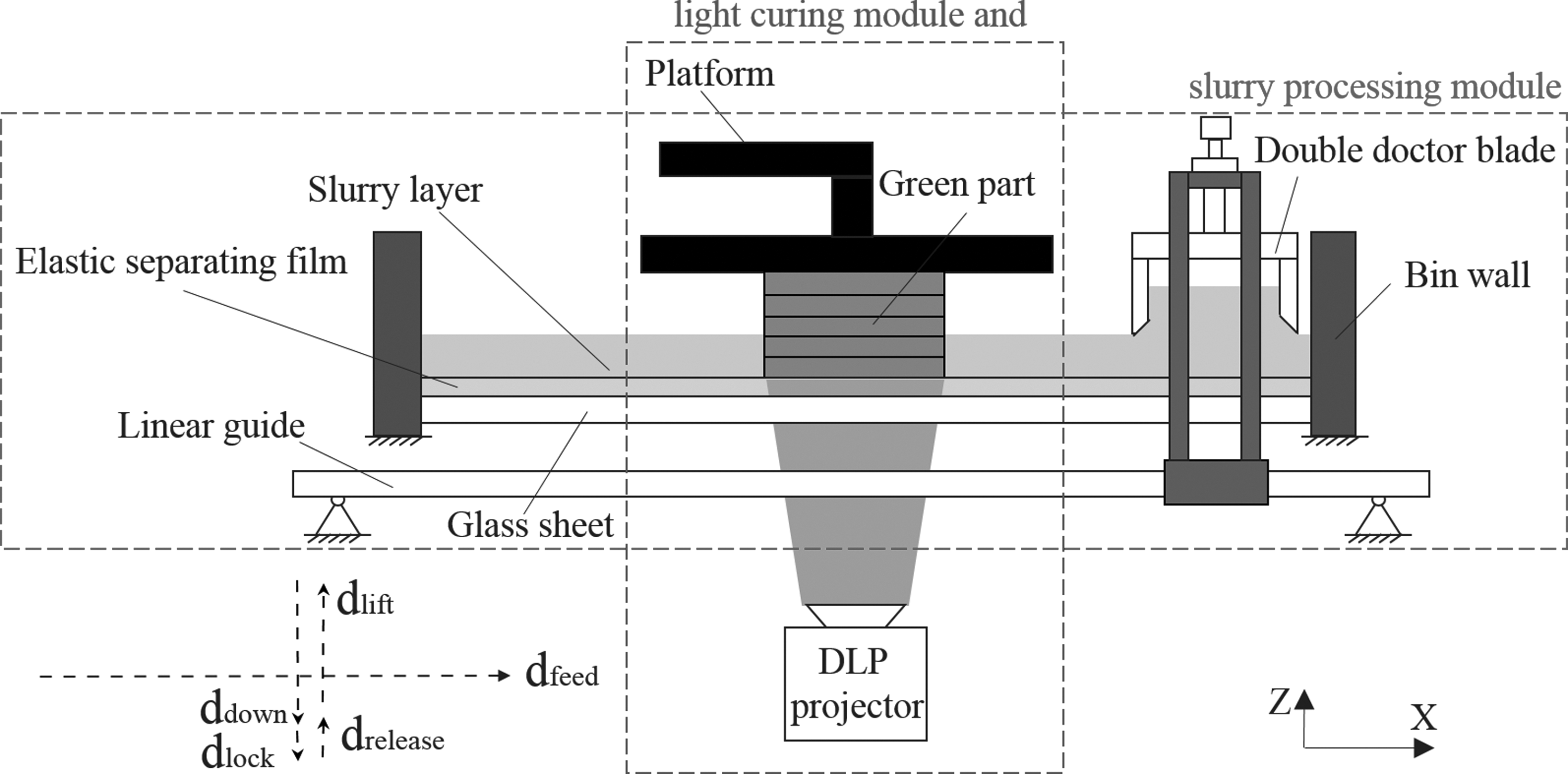
Schematic diagram of the prototype system. DLP, digital light process.
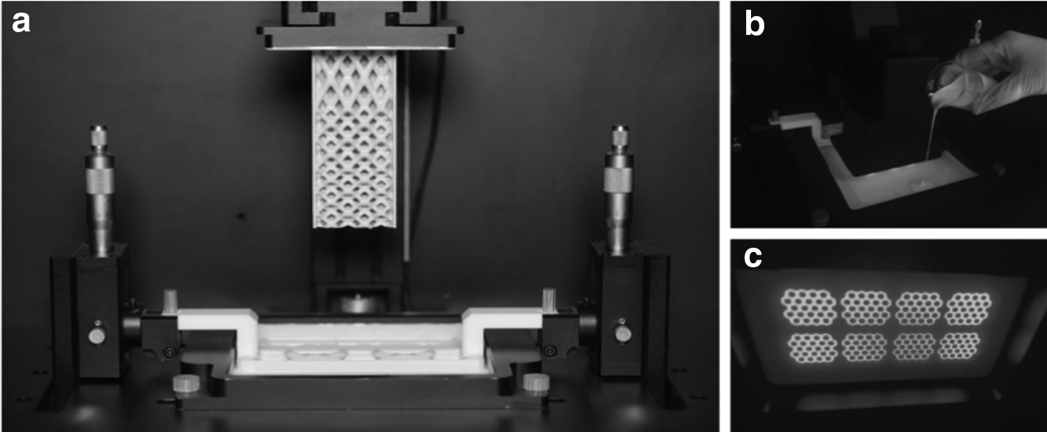
Figure 1 also displays the printing operational process for a single layer. The blade can be moved in the x-direction along the linear guide, and the platform can be moved in the z-direction. The height of the blade (h) is set to form a new layer of reciprocating coating while the blade achieves a shear mixing function on the suspension. After the suspension is paved, the platform descends rapidly by a quantity ddown to a position where it is close to the suspension surface and then slowly descends by a further amount dlock to create a gap δ between the upper layer of the bottom and the release film for a new layer of curing. Following this, the DLP system exposes the material to the photosource for a given amount of time until the layer cures. Finally, the platform moves upward slowly by a quantity drelease, which separates the parts and releases the film. After this stage, the apparatus rapidly moves upward by an amount dlift, causing the blade to move again to the other side to produce the new coating. After the suspension is paved, the molding station drops again by an amount (dlift + drelease − δ), and a new gap is formed in preparation for another new layer of curing. This process is repeated to obtain light-cured complex ceramic blanks. Figure 2 shows the ceramic fabrication test bed: (1) is a photograph of the device, (2) illustrates the process of adding the suspension during printing, and (3) shows the layer exposure area.
CSS recoating system
The double blade in the recoating process plays three roles: (1) coating, as it controls a precise gap between the bottom of the bin and moves accurately in the bin to achieve a thin coating; (2) stirring, as in situ stirring of the suspension occurs on the cusp of the blade, during which mixing from the extrusion between the blade wall and the inner wall of the bin reduces sedimentation; and (3) material storage, as storage of the suspension during printing prevents the suspension from flowing into the printing area, reducing formation defects.
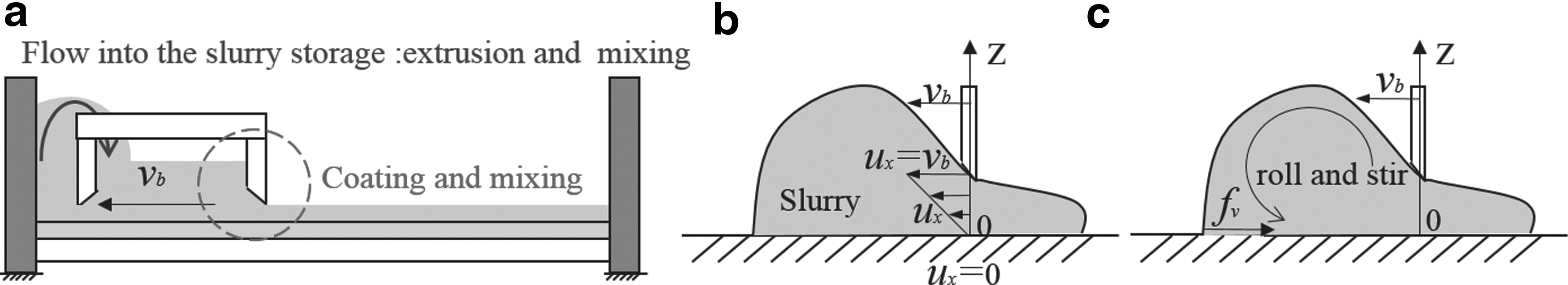
During the recoating process, the suspension at the blade forms a new layer after each movement. From reference, 17 we know that the process of scraper coating can be established into a plane Aikut flow model. The storage/mixing scraper has two parallel grooves, from one side to the side opposite of the scraping; the back of the blade meanwhile plays the role of shearing the suspension. The principle of shearing the suspension is illustrated in Figure 3b.
Force diagram of the spreading process:
When the blade moves at a constant speed vb, the boundary conditions are as follows:
The simplified model of δ′, obtained by solving the Navier–Stokes equation under the boundary conditions, is as follows:
where ρ is the density of the ceramic suspensions; ρ′ is the density of the new layer; δ′ = αδ (α > 1); and α is the safety factor to ensure that the new layer can connect to the previous layer. Therefore, the height h of the blade must satisfy the following conditions:
During movement of the blade, the tool nose can shear the suspension and the bottom of the bin creates friction fv on the suspension, which can cause the slurry in the coating process to rotate at the tool nose, which forms the situ stirring process and prevents sedimentation, as shown in Figure 3c. In addition, when the blade moves to one end, the outer wall of the scraper and the inner wall of the bin will squeeze and shear excess suspension into the storage silo, achieving a controllable mixing function.
High-stretch elastic separating film
The force of separation after the layer printing is the key factor for successful printing. Therefore, a stretch elastic separating film that is fixed around the bottom of the bin wall was designed.
After solidifying a new layer, the bottom of the model is close to the separating film and is surrounded by the spreading layer. In the initial period of model printing, gravity can be ignored. Additionally, the adhesion force between the sample and film can also be ignored because the surface energy of the separating film is very low. Therefore, the main tension of the model is derived from the vacuum generated by the bottom of the model when the stage is raised. First, we assume that the model is surrounded by the suspension. When the model is raised, a gap occurs between the model and the separating film to produce a pressure difference, and the suspension infiltrates from the edge into the gap to equalize the pressure. Figure 4a shows the state of force during the separation of the model, Figure 4c shows the suspension infiltration process of the rigid film, and Figure 4d shows the infiltration process of the suspension in the flexible membrane.
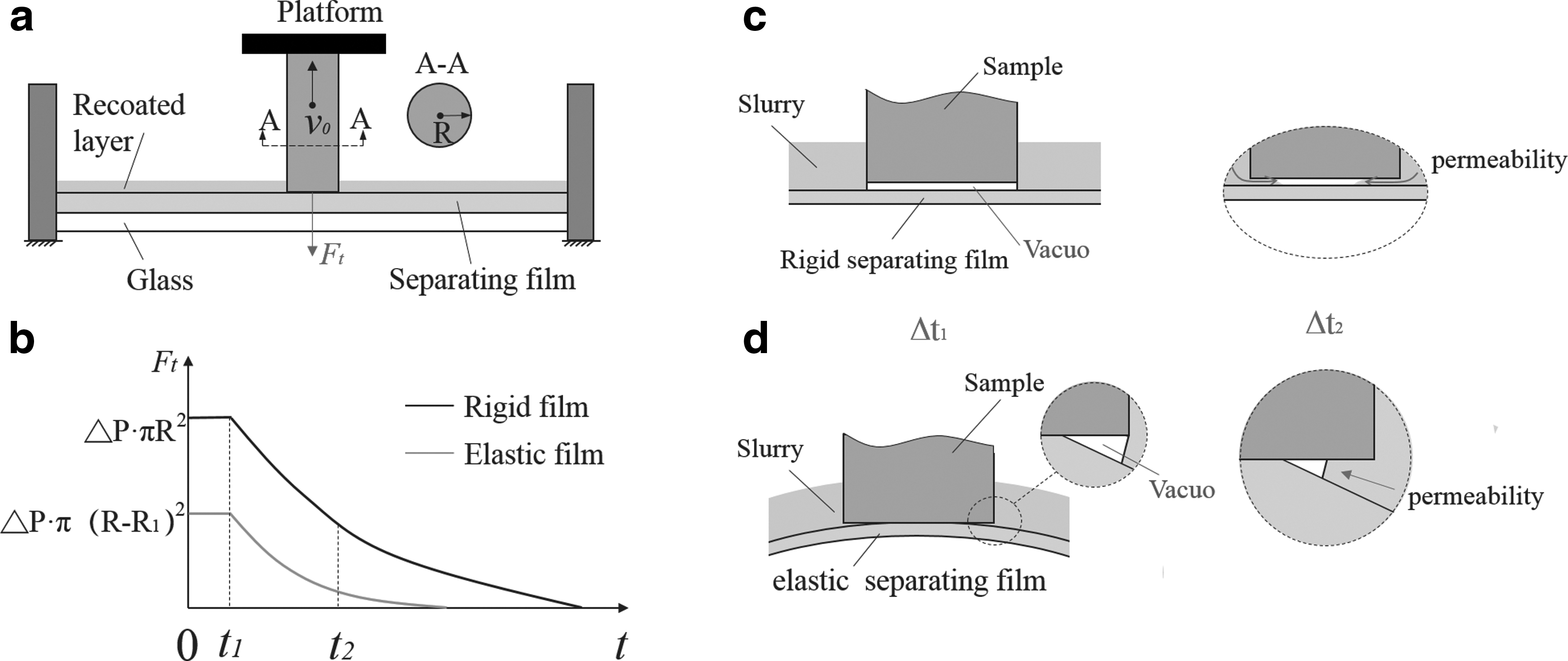
The state of force and suspension infiltration processes when the model is separated:
When the model is moved a certain distance after time Δt1, resulting in an area of vacuum, then it is subjected to the downward force of differential pressure. Maintaining the position of the model, tension decreases with the suspension infiltrating the vacuum after Δt2. If given sufficient time, the area under vacuum will be completely filled with the suspension and tension reduced to 0. Figure 4b shows the state of the model's tension over time in a cycle.
The change in differential pressure and stress state of the model are analyzed under conditions of both flexible and nonflexible release film. Figure 5 shows the suspension infiltration model.
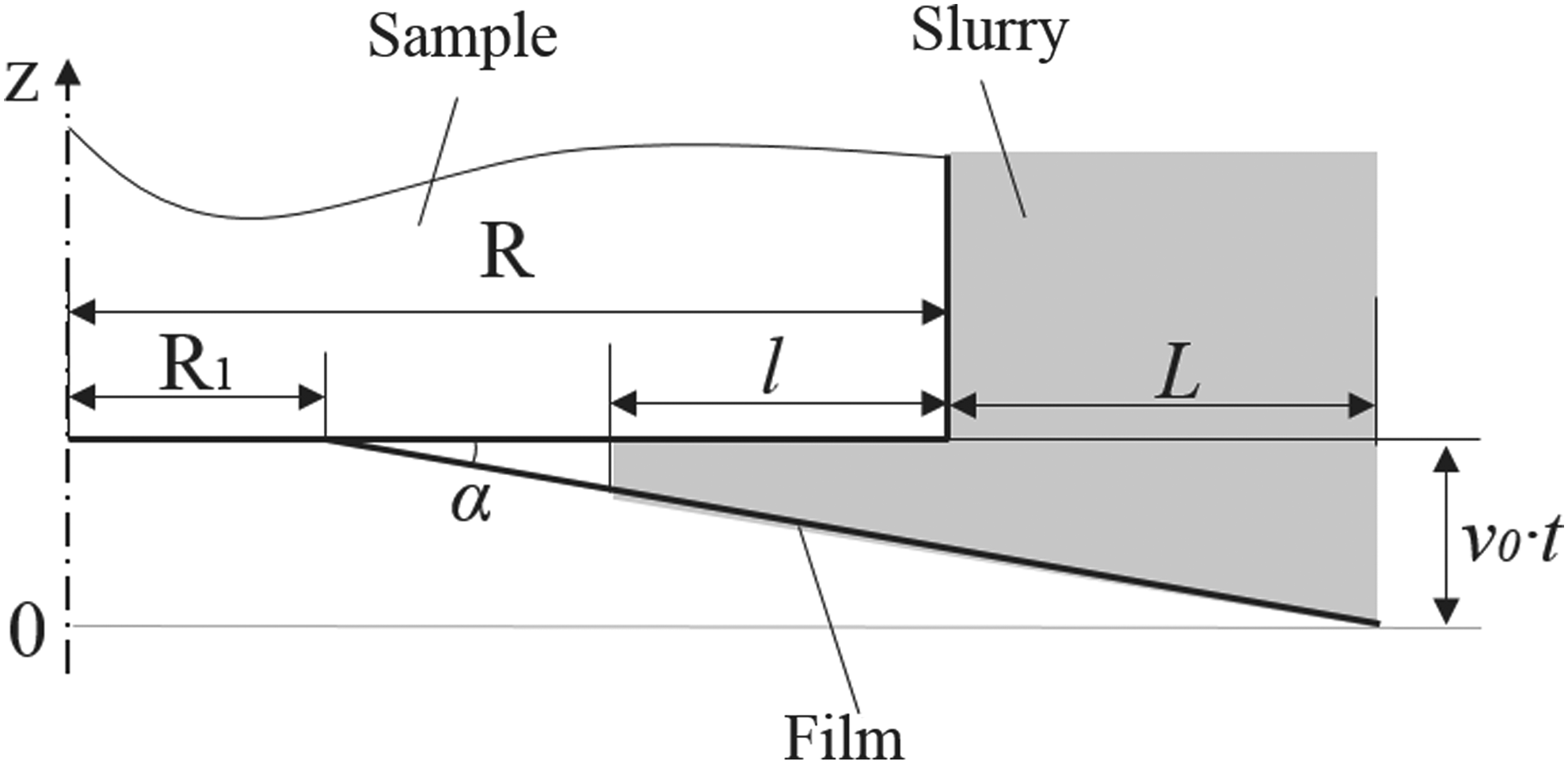
Suspension infiltration model.
The vacuum force of the sample can be equivalent to
where P0 is the atmospheric pressure; R is the model radius; R1 is the radius of the unseparated part between the release film and the bottom of the model, which is a function of v0; and l is the suspension infiltration length. We can describe the infiltration length l using the Washburn equation with external differential pressure:
where r is the capillary equivalent radius; Y is the suspension surface tension; μ is the suspension viscosity;
Therefore, the parameter Ft is defined by μ and v0, and the larger the value of v0, the greater the height of the model in unit time. The smaller the value of R1, the greater the viscosity of the suspension μ. Finally, the smaller the suspension infiltration length l, the greater the vacuum force Ft. Therefore, in the case of high suspension viscosity, reduction of v0 is required to balance the tension in the model.
Materials and Performance
In previous studies, ceramic suspensions were prepared by dispersing the ceramic powder into the photosensitive resin. For this method, it is desirable to select a suitable dispersant depending on the type of resin and powder, and a suitable dispersion process is required.6,8,15 The monomer is polymerized after exposure to the photosource to form a polymeric network as a binder to encapsulate the ceramic powder. The complex green part is then printed layer by layer, the binder is removed, and finally, the ceramic is densified through high-temperature treatment.
In the process of ceramic SL, solid loading is an important factor as it affects the physical properties of suspensions and sintered parts. In theory, solid loading above 40 vol% can be sintered 16 ; the higher the solid loading, the smaller the sintering shrinkage, densifying will be easier, and mechanical properties will be improved. However, higher solid loading may reduce the penetration depth of polymerizable suspensions and make the solidification process difficult, except for coating problems caused by greater viscosity.
Theory of ceramic photopolymerization
The relationship between cure depth and energy input of exposure is defined by the Jacobs equation:
where Cd is the cure depth of the ceramic suspension after energy input; E0 is the energy density of incident light on the upper surface of the film; Ec is critical energy density, that is, the minimum energy for photocurable materials to be solidified; and Dp is sensitivity of resin. Ec is related to photoinitiator activity, the inhibiting effect of the artificially added inhibitor, and residual oxygen. Dp is related to photoinitiator absorption and the type of absorber (e.g., dye) in the resin, in addition to light scattering by mixed particles. According to predictive models by Tomeckova and Halloran for photopolymerization of ceramic suspensions, Dp can be determined by the following equation
18
:
The sensitivity depends on absorption and scattering. The scattering parameter, S, is defined as S = 1/lSc and an absorption parameter, A, as A = (ɛPcP + ɛDcD), where cP and cD are photoinitiators and dye concentrations in moles/volume unit of the monomer, respectively. ɛP and ɛD are molar extinction coefficients of the photoinitiator and the dye. lSc is related to d50 (the average particle size),
where Q is the concentration of artificially added inhibitor; γQ is the number of radicals removed per inhibitor; O is the concentration of oxygen inhibitor; γO is the number of radicals removed per oxygen inhibitor; γD is the number of radicals that were not generated because the photon was absorbed by an inert dye; and Ω is the number of radicals created per absorbed photon.
Preparation of suspensions and their curing characteristics
In our study, different ceramic powders are tested using the presented ceramic fabrication process. They include alumina (AW-SF; Hechen, Henan, China), silica (FS-5000; Fucai, Jiangsu, China), and zirconia (JA-TZP-3Y; Jin'ao, Shandong, China). First, the powders must be dried at 120°C for 12 h and then added to the monomer, which is followed by ball milling with zirconia media in a ball mill (QM-3SP04L, Nan'Da, China) at room temperature for 12–24 h based on the design ratio. The photoactive ingredients, which include the photoinitiator, absorber, and inhibitor, are added into the mixture, which is then milled at 250 rpm for another 1–2 h. Before ball milling between the resin and powder, dispersant can be added to resin during machine mixing; the powders are subsequently added in batches during machine mixing (Euro-star 60 digital; IKA, Germany).
Pure resin at 25°C has a viscosity of 32.6 mPa·s and a density of 1.03 g/cm3. Resin was selected in our study due to its excellent photosensitivity and low viscosity. This resin contains 50–80 wt% 1,6-hexanediol acrylate monomer, 10–25 wt% acrylated monomer, 0–1 wt% absorber, 0–1 wt% inhibitor, and 0.5–1.2 wt% photoinitiator.
For different ceramic materials, we not only need to reduce the viscosity to make the coating easier but also need to control the cured depth and additional cured width from scattering based on the performance of different powders to ensure model molding and accuracy. For example, with silica, the absorbent material with a lower refractive rate, an appropriate amount of absorbent is needed to increase the attenuation coefficient of the suspension to control layer thickness. For alumina and zirconia, which are types of materials with large refractive rates, an appropriate amount of inhibitor is needed to increase the critical energy of suspensions to mitigate the effects of scattering. Therefore, we prepared three kinds of resins: No. 0 resin containing no absorber and inhibitor, No. 1 resin containing absorbent without inhibitor, and No. 2 resin containing inhibitor without absorbent.
The suspensions that were obtained had high solid loading with low viscosity, which were suitable for the 3D printing parameters of the system. Among these parameters, the solid content of alumina and silica was 60 vol%, the solid content of zirconia was 52 vol%, and its viscosity was also within the scope of adaptation. Table 1 contains the parameters for three types of suspensions and pure resin.
Parameters of Three Kinds of Suspensions and Pure Resin
Finally, the mixture was degassed in a vacuum chamber for 20 min to remove air bubbles produced in the process and to reduce inhibition polymerization and sintering defects.
Figure 6 shows cure depths for three different types of ceramic suspensions that were measured using the prototype system. A single-layer curing method was used for measurement of cure depth in these ceramic suspensions. An image of a circle with a 10 mm diameter was projected from below onto the ceramic suspensions after the suspensions were coated by the doctor blade. Choosing different exposure times results in different levels of curing of the thin layers of ceramic composite, and these thicknesses can be measured by a micrometer caliper.
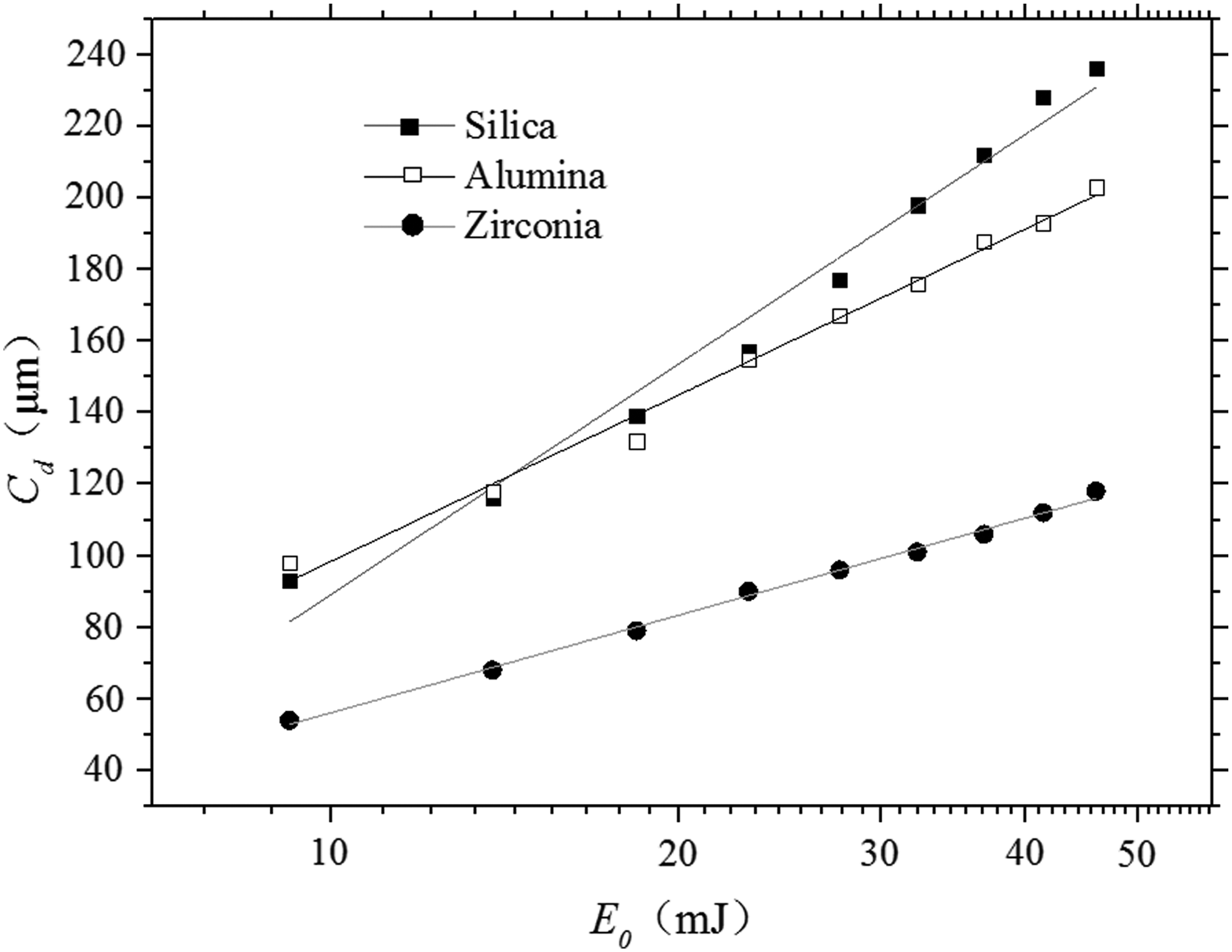
Cure depth versus energy dose for three different suspensions.
As such, layer thickness during the fabrication process must be chosen appropriately such that the cure depth is larger than the set layer thickness to ensure good bonding between layers. The light intensity measured at the surface of the release film is 6.5 mW/cm2.
Experimental Results
Green part printing of high solid loading suspensions
Table 2 shows the molding parameters selected during the printing process for different suspensions. These parameters vary according to characteristics of the suspensions and types of equipment used. Since zirconia suspensions are the thinnest, the thickness of consequent layers is also the smallest. Silicon oxide is the thickest, but layer formation thickness can be controlled by addition of an absorbent. Figure 7 shows various green part components using silica, alumina, and zirconia suspensions.
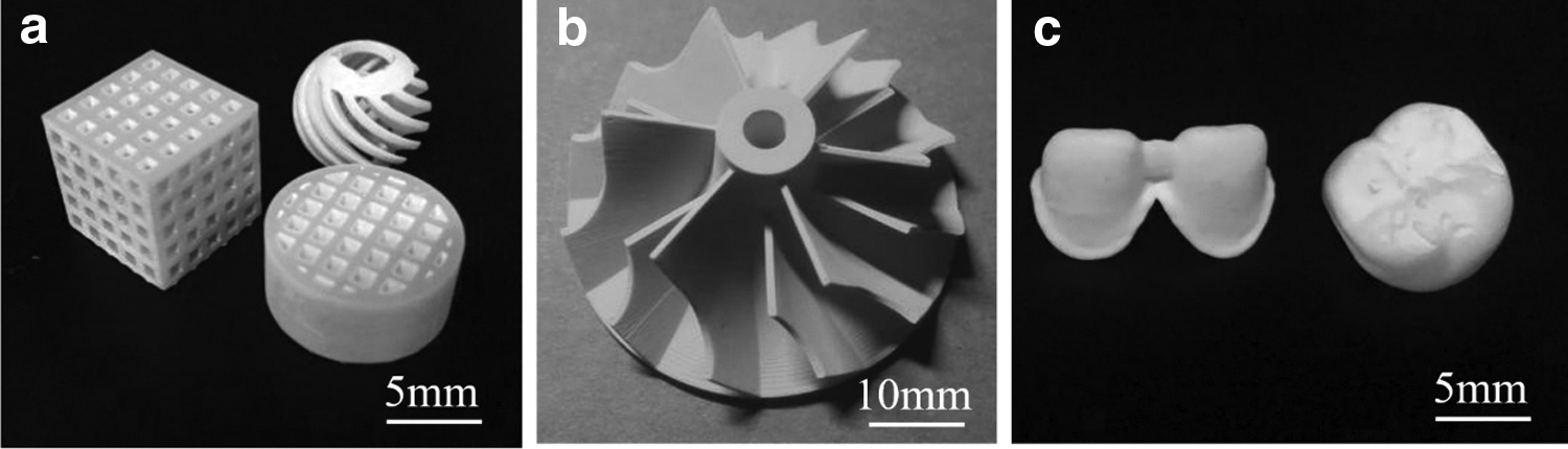
Green part components from different suspensions:
Printing Parameters of Different Suspensions
Alumina brown part and testing results
The green fabricated parts consist of two faces: organic binder and ceramic powders. After the green parts are produced, further postprocessing is required to achieve dense ceramic components.
Alumina printing samples, for example, undergo thermogravimetric analysis-differential thermal analysis tests designed for appropriate degreasing and sintering temperature systems to obtain the final sintered products. To make a slow stepwise process for organic matter removal, a number of intermediate temperature steps were set for warming to finally achieve and maintain a temperature of 600°C for 2 h. After debonding, the sample was placed in a muffle furnace and heated to 1650°C for 2 h to obtain the final densified alumina part. Alumina brown parts with complex lattice structures are shown in Figure 8; the minimum structure size is 0.25 mm.
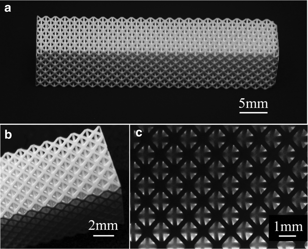
Alumina brown parts with complex lattice structures:
After sintering, shrinkage of the prepared ceramics was measured against a cuboid sample (30 × 10 × 4 mm) and was found to be ∼12.5%. Such shrinkage can be compensated by enlarging the original CAD model by a corresponding amount. Figure 9 shows the scanning electron microscope (SEM) images of the green and sintered parts: (1) shows SEM images of the cross section of the green body, in which it can be seen that particles are evenly distributed in the solidified organic binder and the green body is uniform; and (2) shows SEM images of the polished surface after sintering, in which the interface between particles can be clearly seen. There is also a small concentration of pores at the grain boundary, and sintering is not fully achieved. A density of 97% of true alumina (3.96 g/cm3) is obtained in the sintered block samples. The results from the green part and sintering verify the superior performance of the fabrication test bed and high solid loading suspensions.
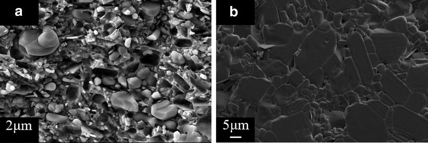
SEM images of samples:
Conclusions
A ceramic SL shaping system with a special recoating system was designed that integrates in situ coating, storage, and stirring processes, which has allowed production of ultrathin layers using high-viscosity ceramic suspensions. Sedimentation was prevented by stirring and extrusion mixing, which kept the green body uniform for improved sintering. Along with a well-designed scraper storage function, this can reduce feeding times, ensuring that any excess suspension does not affect the printing process. A stretch elastic release film has also been designed. The separating force is significantly lower than that of rigid film and is affected by suspension viscosity and lift speed v0. The elastic release film design reduces the tension of separation and fracture probability of the model, in which more fine structures can be formed. The ceramic suspensions with high solid loading and low viscosity were prepared using a calculated formula, and the photopolymerization performance was adjusted for the different powders. Appropriate molding parameters were selected for the green part, as for the three different prepared suspensions, using a designed molding system. Finally, debonding and sintering of the alumina model were studied, and sintering properties were characterized. Sintered parts with shrinkage rate of ∼12.5% and density of 97% were obtained, and the three-point flexural strength was found to be 400 MPa.
Footnotes
Acknowledgment
The authors are grateful for the funding from the Tribology Science Fund of the State Key Laboratory of Tribology, Tsinghua University: SKLT2016B06.
Author Disclosure Statement
No competing financial interests exist.