
Abstract
Abstract
One of the leading causes of print failure is the filament feeding mechanism. By surveying the literature and leveraging our current experience in hardware development, we have identified a gap in the knowledge base for understanding the mechanics and operations surrounding the extruder drive gear commonly used on fused filament fabrication (FFF)-type 3D printers. The goal of this work is to characterize the amount of force that can be generated by a novel extruder drive bolt, affectionately named Jaws. The testing outlined below was performed with a Greg's Wade–type extruder for 3 mm polylactic acid (PLA) filament.
Introduction
W
One of the leading causes of print failure is the filament feeding mechanism. By surveying the literature 1 and leveraging our current experience in hardware development, we have identified a gap in the knowledgebase for understanding the mechanics and operations surrounding the filament drive gear commonly used on fused filament fabrication (FFF)-type 3D printers.
We suspect the reliability of the filament feed gear is dependent upon three factors: (1) size of contact surface between the drive gear and the filament; (2) depth of the gear's tooth engagement into the filament; (3) number of teeth engaged in the filament at any one time; and (4) the direction of the force vector imparted by the filament drive gear into the filament. R&D at re:3D has delved into this problem and below is the result of their work.
The goal of this work is to characterize the amount of force that can be generated by a machined extruder drive bolt, affectionately named Jaws. Figure 1 shows a 3D rendering of the filament drive gear, Jaws, that will be mounted to the shaft of a geared NEMA 17 stepper motor. The testing outlined below was performed with a Greg's Wade–type extruder for 3 mm polylactic acid (PLA) filament (see Fig. 2).
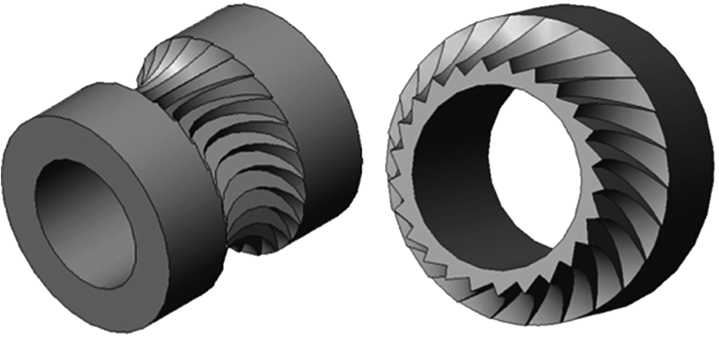
Jaws filament drive gear and mid-section view of Jaws filament drive gear.
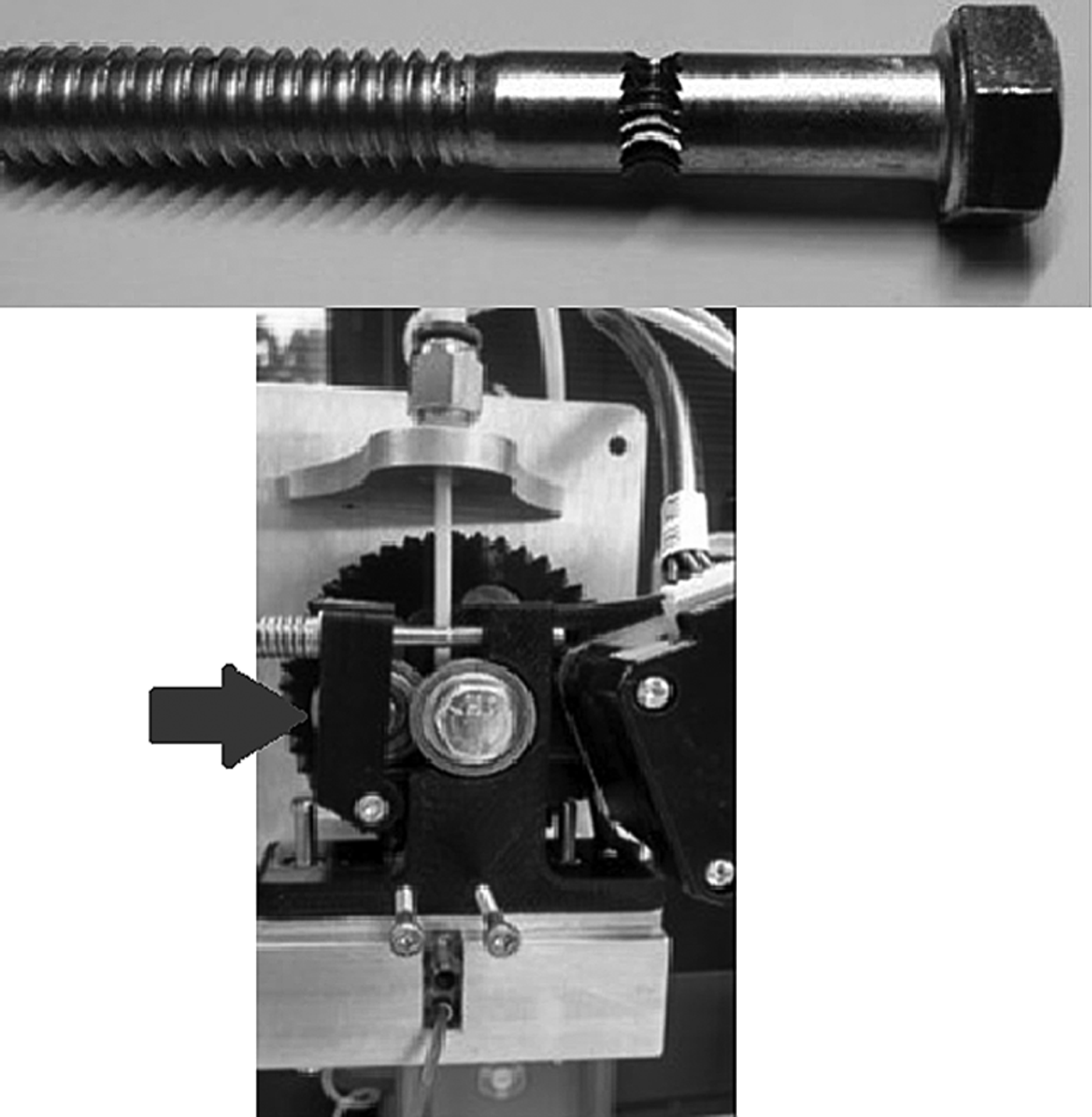
Tensioning system and force arrow with Jaws filament drive bolt.
Materials and Methods
The Jaws filament drive gear is machined using a four-axis computerized numeric control milling machine. In the design process, our aim was to optimize the four variables stated above.
• The amount of contact between the drive gear and the filament is maximized by machining the gear teeth using a cutting tool of the same diameter as the filament it will drive. In our case, the filament is 3.0 mm in diameter.
• The depth of tooth engagement was optimized by balancing greater tooth engagement against the number of teeth engaged into the filament at any one time. If the tooth engagement is too shallow there will be too little surface area and too little force imparted to the filament. The teeth will slip and shred the filament. If the tooth engagement is too great, the risk of plastic deformation causing the filament dimension to be out of specification for the hot-end will cause jamming of the hot-end during printing.
• The number of teeth engaged into the filament at any one time is important in maintaining a smooth and constant push of filament into the hot-end. Consider the job of the filament drive gear being to transform the rotational motion from the stepper motor into straight line movement of filament into the hot-end. If too few gear teeth are engaged into the filament, the linear motion of the filament over time will assume more of a sine wave pattern than a constant straight line movement.
• The force vectors should be directed in the downward direction as much as possible to increase the conservation of energy in the system. Any forces imparted into the filament in the lateral direction will cause plastic deformation of the filament and not translate into pure downward force of the filament feed. It should be noted there will always be a certain amount of lateral force experienced for the pure fact that the drive teeth will need to be engaged into the filament. By studying the section view in Figure 3 you can see the depth of engagement, the number of teeth engaged, and the force vector for a 25-tooth drive gear.
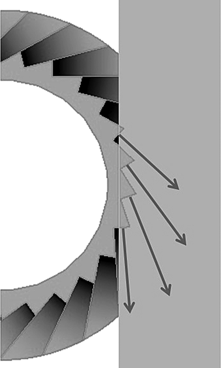
Tooth engagement, number of teeth engaged, and force vector.
You can view a short video of the machining process on our re:Tech YouTube channel.
The first objective of this study is to determine the optimal tension setting for the Greg's Wade extruder. Tension is adjusted by rotating a pair of screws that compresses a pair of springs, which in turn presses the extruder's idler bearing against the filament (see Fig. 2).
If the tensioner is adjusted too loosely, the filament will not fully engage against the teeth of the drive bolt. If the tensioner is adjusted too tightly, there may be excessive friction and wear in the extruder. To accurately measure the force imparted to the filament by the extruder we felt it was important to measure the ability of the extruder to push the filament down into the hot-end. Previously, force measurements 2 measure the amount of pull the extruder imparts in the filament coming into the extruder. We felt that by measuring the amount of push we would obtain better real-world operating conditions.
The downward force measurement was accomplished by a custom machined fixture that housed a small metal ring outfitted with a threaded tensioning system. The tensioning system is used to slowly grip the filament by turning a screw. As the ring increases its grip on the filament, the force is transferred from the filament and onto a compression load cell (THA-100-Q from Transducer Techniques). The load cell was connected to a load cell amplifier (TMO-1 from Transducer Techniques), and the analog output from the amplifier was measured by a 12-bit A to D daq (USB-1208LS from Measurement Computing). Data was collected at 100 Hz and saved to csv file format. The daq was calibrated using a mass of solid brass and aluminum of known volume. Collected data was processed and graphed using custom Matlab code. The extruder is driven with a 1.68 A 72 oz-in NEMA 17 stepper motor powered at 24 volts. The test setup can be seen in Figure 2 above. All testing was done with a hot-end temperature of 210°C.
Results
Three trials were performed at four different levels of tensioner adjustments. Tensioner adjustment levels were determined as 2, 4, 8, and 12 revolutions (1 revolution = 360 degrees of rotation) of the tensioner adjustment screw beyond full engagement into its corresponding nut. Example trials are shown below. Notice in the data graph the period of zero force at the beginning of the trial is followed by a gradual increase of force. The force curve shows the peak force imparted into the filament followed by a sharp drop in force where the filament drive gear stripped the filament, and the filament drive bolt was no longer able to impart a force into the filament.
Discussion
The graphs seen in Figures 4 and 5 demonstrate the ability of the filament drive bolt to drive the filament at increasingly greater forces with an increase of tension in the extruder tensioner system. Figure 4 shows the peak down force achieved with two and four turns of the filament drive tensioner. Figure 5 shows the peak down force achieved with 8 and 12 turns of the filament drive tensioner.
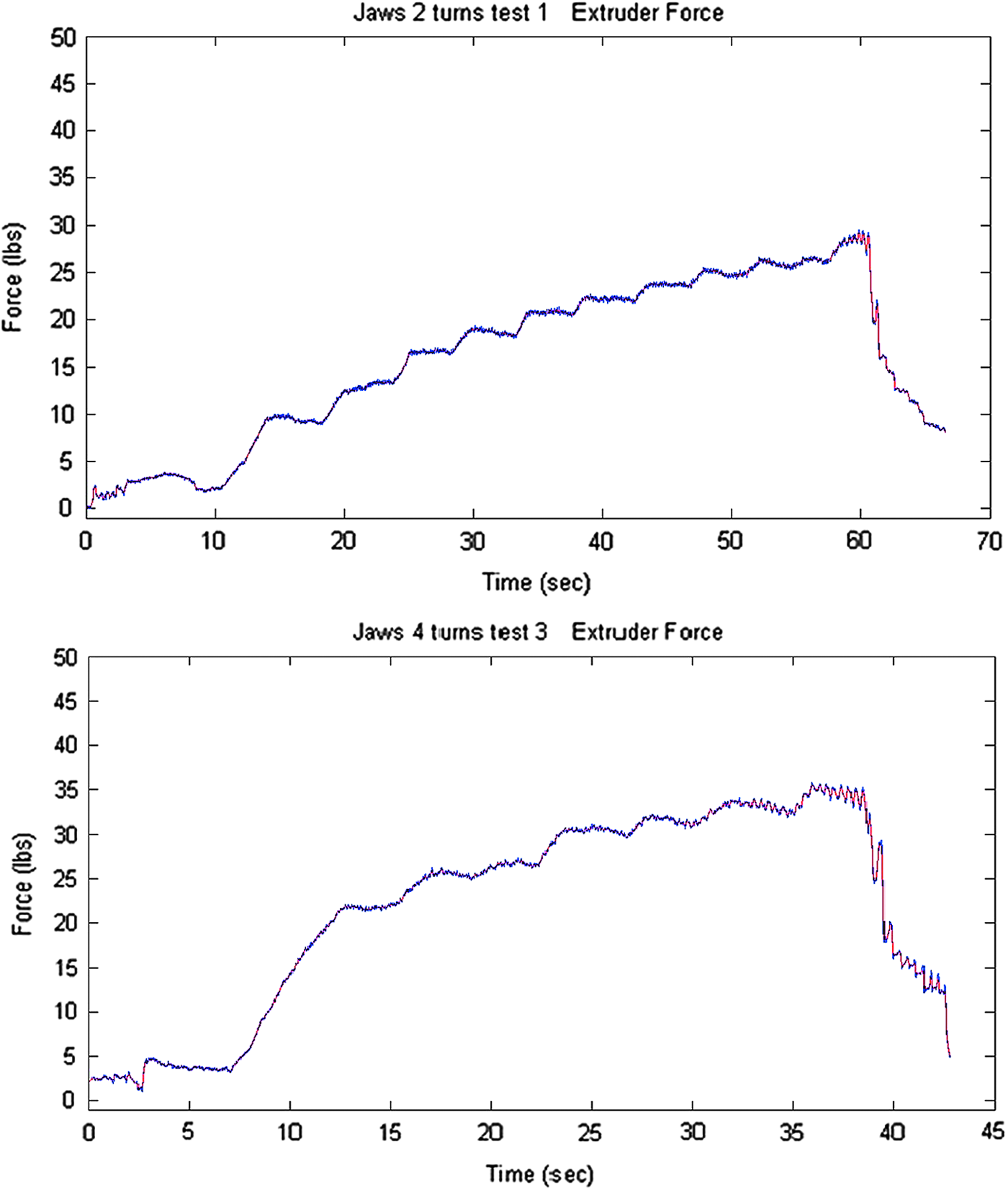
Tensioner tightened two (top) and four (bottom) revolutions. Color images available online at www.liebertpub.com/3dp
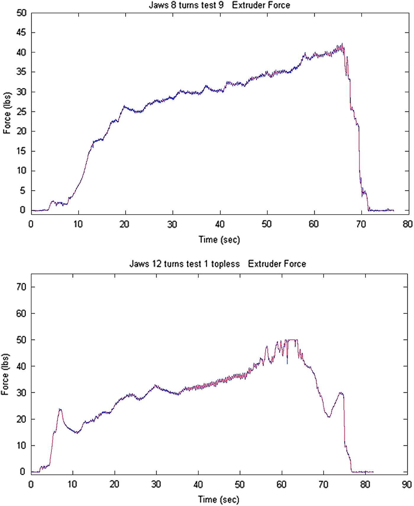
Tensioner tightened eight (top) and twelve (bottom) revolutions. Color images available online at www.liebertpub.com/3dp
Conclusion
What does this mean for you? With the Greg's Wade–type extruder and the novel Jaws filament drive bolt, we were able to push the PLA filament with over 50 lb of force when the extruder spring tensioner was advanced 12 revolutions. This research establishes a baseline measurement for re:3D's custom extruder bolt, which was designed to maximize the grip on PLA filament and help ensure an error-free printing experience. This research was conducted at the office of re:3D in Houston, Texas.
Footnotes
Author Disclosure Statement
No competing financial interests exist.