
Abstract
The European rules of timber structural design do not include distinct rules on carpentry joints. As a contribution towards filling this gap, this study into the existing knowledge of the most commonly used carpentry joint, the single-step joint, is performed. The design rules of three European countries and the latest developments on the topic are discussed. This study shows that the knowledge of expected stress distributions as a consequence of the geometric shape is important to achieve the intended reliability level for joints. The investigation indicates that further research on the combination of shear and compression forces is necessary to improve and include in the design rules in Eurocode 5.
Introduction
For centuries, carpentry joints have been crafted by carpenters, and the production methods have been bound by traditions. Many cultures have had their own joinery traditions, and in cultures such as the Chinese or Japanese, these traditions have been strong. In Europe, the traditions for structural joinery are closely related among the different countries but are not equal. When the Commission for the European Community in 1975 decided on an action programme to eliminate technical barriers to trade in the construction sector, carpentry joints were not given priority. Modern joining techniques were a focus in the effort to develop common rules in Europe. Effective joints with regard to both industrial production and load-carrying capacity were included. Thus, carpentry joints were not mentioned in Eurocode 5 (CEN 2004). Some European countries still considered these joints important, and thus, they included some rules in their national annexes. Consequently, these national rules are not harmonised and vary between different countries.
Development of computer numerical controlled (CNC) milling machines has given carpentry joints a renewed interest. It is now possible to produce them effectively and economically with high precision. As a consequence, the design can be slightly different from traditional carpentry joints. To facilitate the evaluation and design of carpentry joints, an overview of typical carpentry joints was carried out by Siem and Jorissen, and the assessment and design was discussed based on European standards (Siem & Jorissen 2015). In this paper, the most used joint – the single-step joint – is described and discussed further. The single-step joint is able to effectively transfer large loads and is frequently used in practice and thus is the most important carpentry joint type. Reviewed literature is limited to the literature collected for a previous study (Siem & Jorissen 2015).
The upper left panel in Fig. 1 shows a traditional single-step joint where an inclined compression timber element meets a vertical element. The picture is a detail of a bell tower structure in France. In the top right in Fig. 1, a two-sided single-step joint between a king post and the diagonals is shown. This example is from Greece and shows a solution often used in roof trusses in Europe. The bottom left of Fig. 1 shows a simple milling produced with a modern CNC machine, and the bottom right of Fig. 1 shows a more complicated detail made with the same machine. The lower right panel is a rounded dovetail connection, which is a part of a beam-to-beam connection. Complex geometries can currently be realised due to accurate design and manufacturing of the connections.
Step joints in the upper panels, CNC milling examples in the lower panels.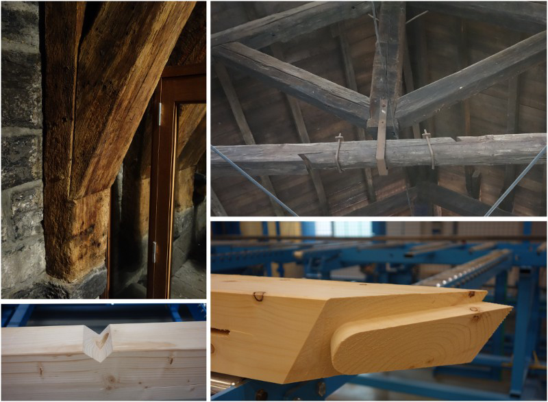
The design rules of three European countries have been chosen for discussion because they are comprehensive and the best documented. No additional arguments were found in any other country's rules. Documents from the Swiss standardisation process (Dubas 1981; Jockwer & Steiger 2009; Jockwer & Steiger 2010) and textbooks (Rasmussen 1949; Dröge & Stoy 1985; Ehlebeck & Kromer 1995) have been valuable for the study.
Failure modes and forces
The single-step joint is used where a compression element meets another element with an angle φ, as shown in Fig. 2(a). The normal range for the angle φ is between 20° and 60° (Dröge & Stoy 1985). In the horizontal element, a notch is made with a depth tv. The compression load in the inclined element is mainly transferred to the horizontal element through the front area shown as the line AB; thus, the most important failure modes in the joint are compression failure along the line AB, shear failure along the dotted line between B and D or tension and bending failure in the reduced section along the dotted line between B and E. Compression failure perpendicular to the grain in the surface BC is generally not a problem with proper geometric design (Blaß et al. 2005).
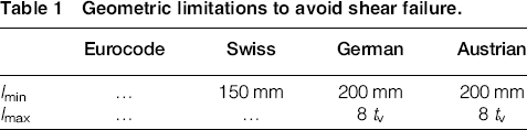
Geometry and forces in a single-step joint. Support is not shown. The shear stresses of e are an indication of the shear distribution along BD and are based on Krabbe (1962).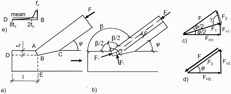
Different step joint geometries and calculation models were discussed by Troche (1936). The compression force in the joint was decomposed into two forces 90° to the surfaces AB and BC, as shown in Fig. 2(a). It was assumed that friction was not transferred along the surfaces. The angle ABC has to be at least 90° to avoid splitting along the line BD. When calculating the capacity for stresses with an angle to the grain, Troche used a linear integration between the capacity in the fibre direction and transverse to the fibre direction as a failure criterion. When the shear capacity was calculated along the dotted line BD, a minimum length of 150–200 mm was assumed. The recommendation for constructing step joints was adjusted by Troche (1956, 1958). The most important conclusions can be summarised as follows: the simple step joint should be analysed as a hinge, and the effect of shrinkage and friction on the load-carrying capacity is ignored. Stresses in a single-step joint were analysed by Krabbe (1962). The analytical results showed large variations in the shear stresses along the dotted line BD. The shape was similar to a half hammock with high stress levels close to B, as indicated in Fig. 2(e). The main principles in these analyses are still acknowledged in the design rules today. One of the difficult continuing issues is how friction affects the load transfer. The two extreme models for transferring the compression load through the surface AB are shown in Fig. 2(c) and (d) without and with friction, respectively, along the surface. Fig. 2(b) shows the compression force F decomposed in the forces F1 and F2, which are both perpendicular to the contact surfaces. This force decomposition assumes no friction in the contact surfaces. Because the shrinkage of the wood in the fibre direction is small compared to that perpendicular to the fibre direction and because the elements often contain more moisture than the resulting long-term equilibrium situation, the connection often opens up at the contacting surfaces between B and C and the forces concentrate around B. This force concentration results in an eccentric force in the compression element represented by F and e in the figure and thus results in bending moments in this element. In the figure, the surface AB has an angle
 . This gives the force F1 an angle between the force and the fibre direction equal to
 and is the optimal angle if the material quality is equal in the two elements. The reason is that the largest angle between the force and the fibre direction then will be the lowest possible and will be equal in the two meeting surfaces along AB. The angle γ between the two notch surfaces is shown to be larger than 90° in the figure. If the angle is <90°, the force can act as a wedge and result in unintended tension perpendicular to surface BD, as mentioned above.
In Fig. 2(c), the directions for the two forces F1 and F2 are shown with an angle γ, corresponding to Fig. 2(b). The dotted line represents the position of F2 if ϒ = 90°. The force F1 can be expressed as follows:

 ° and is expressed as follows:
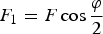
Fig. 2(d) expresses the model with friction along surface AB. Then, the force F can be transferred to the surface AB as the force F3 and be decomposed in the horizontal force FH2 and the vertical force FV2. In this model, the angle between the force F3 giving compression on the front surface AB and the fibre direction will be φ, which is twice as large as that in the first model. The horizontal component FH2, giving shear stresses, will be smaller compared to FH1 in the first model.
Parisi and Piazza (2000) showed that single-step joints are semi-rigid and can transfer non-negligible moments.
Compression in the front surface AB
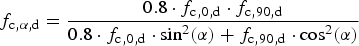
As described in the last section, three failure modes can be identified. For design compression stresses with an angle to the fibre direction, α, the general formula in Eurocode 5 is based on the work of Hankinson (1921) and is expressed as follows:
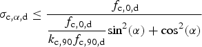
The Austrian code (Institute 2014) has a normative annex on single-step joints, but the design stresses for the front surface are not mentioned and thus refer to the main part of Eurocode 5 as described above.
In the Swiss code (SIA 2003), the corresponding design value is expressed as follows:
The design rule is, as in Eurocode 5, based on Hankinson (1921), but the design value for compressive stresses parallel to the grain is reduced to 80%. According to Jockwer and Steiger (2009), the reduction takes into account the consequences of inaccuracy in the production of the geometry of the joint.
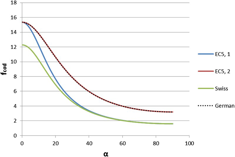
The design rule in the German annex (DIN NBNi 2010) is based on another failure criterion (Norris 1962). The Norris criterion includes shear, where fv,d is the design value for the shear strength. In the design rule, the design values for both shear and compression perpendicular to the grain are increased by a factor of 2. Blaß et al. (2005) explain the increase in the design value for compression perpendicular to the grain with the spreading of the stresses into the timber. The increase in the shear value is not explained. As shown by Siem and Jorissen (2015), increasing the shear value in the Norris criterion will lift the curve in the middle region. The design rule in the German annex is expressed as follows:
Failure criteria for GL24h.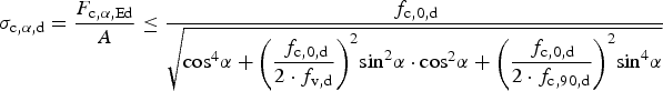
Shear stresses along BD
Shear failure along the dotted line between B and D with length l in Fig. 2(a) is one of the important failure modes, as mentioned. In Eurocode 5, the design rules for shear are expressed as follows:

Geometric limitations to avoid shear failure.
In both models, when transferring a compression load to surface AB discussed in Fig. 2(e) and (d), a horizontal force component FH causing shear stresses along the dotted line BD and, at the same time, a vertical component FV causing compression perpendicular to the grain are identified. The effect of the compression perpendicular to the grain is not taken into account in the presented design rules.
Steiger and Gehri (2011) reviewed existing failure criteria and design approaches concerning combined stresses perpendicular to the grain and shear. Figure 4, based on that report, shows the mean value of 354 test results. The interaction between shear and stresses perpendicular to the grain is strong. Increasing the compression perpendicular to the grain results in increasing shear capacity. The interaction is included in the general design rules in the Swiss standard.
Combined shear and stresses perpendicular to the grain based on the work of Steiger and Gehri (2011).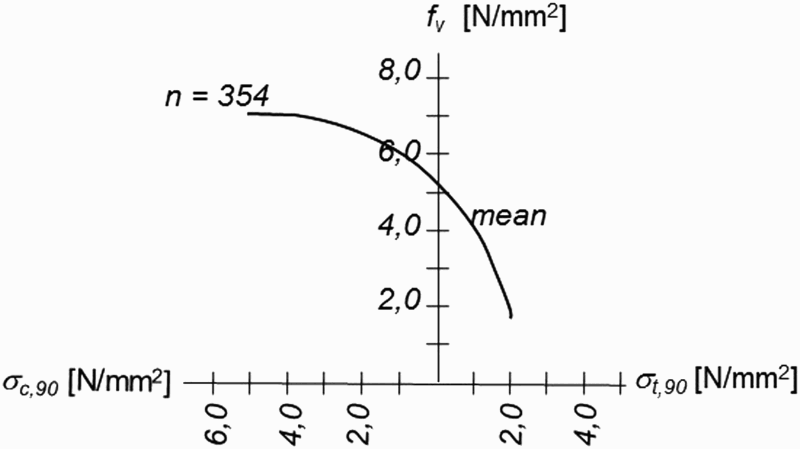
The semi-rigid effect documented by Parisi and Piazza (2000) can increase the tension perpendicular to the grain compared to the discussed models and should be paid attention when developing models including shear and stresses perpendicular to the grain.
When EN 14080 (CEN 2013) replaced EN 1194 (CEN 1999), the system for mechanical properties was changed. In EN 1194, the characteristic value for shear, fv,k, varied between 2.2 and 4.3 N/mm2 for the glulam qualities GL24c – GL36h. In EN 14080, fv,k = 3.5 N/mm2 for all these glulam qualities. This is a change that affects the calibration of the design rules.
Faye et al. (2008) reported an experimental investigation of single-step joints. The experiments were carried out with two different angles φ (25° and 55°), with φ as defined in Fig. 2(a). The length l was either 150 or 200 mm in all the experiments, and the material quality was GL 24. The medium shear strength fv was 3.6 N/mm2 for the 30 experiments where φ = 25°, and fv = 5.1 N/mm2 for the 18 experiments with φ = 55°. The mean shear strength was 40% higher for the tests with the highest angle φ and thus the highest compression perpendicular to the grain. The mean value fv = 3.6 N/mm2 corresponds to a characteristic value of fv ∼ 2.7 N/mm2 and is too low to satisfy the characteristic value at fv,g,k = 3.5 N/mm2 in EN 14080. These results indicate that the angle of the force F in Fig. 2 is important for the compression stresses close to B along the dotted line BD in the area where the shear stresses in Fig. 2(e) are indicated to be higher than the mean value. Steiger and Gehri (2011) showed that the shear strength depends on compression stresses perpendicular to the fibre direction. Further research should thus be carried out to establish failure criteria describing the shear strength with the probability level provided in EN 1990 (CEN 2002).
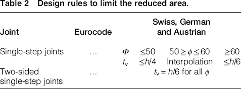
Bending – reduced area along BE
Design rules to limit the reduced area.
Discussion and recommendations
The European design rules of timber structural design do not include distinct rules on carpentry joints. The three discussed sets of design rules on single-step joints show that different rules are used for load distributions of compression and for shear distributions. The latest knowledge on the effects of combined shear and compression stresses is not included in any of the design rules.
This study shows that knowledge of expected stress distributions as a consequence of geometric shape is important to achieve the intended reliability level. The investigation indicates that further research on the combination of shear and compression forces is necessary to improve and include in the design rules in Eurocode 5.
To utilise the new possibilities provided by CNC machines to their full potential, it is important to develop design rules so that the joints can fully be exploited. Including them in Eurocode 5 would be favourable.