
Abstract
One of the tribological requirements on engine bearing material is its ability to safely embed contaminant particles onto its surface and minimise damage to both the bearing and crankshaft surfaces. In this work, a journal bearing test rig that operates under constant load has been employed to investigate the embeddability behaviour of selected multi-layered Pb-free engine bearing materials at three different rotational speeds using engine oil contaminated with SiC particles. Experimental results have shown that third-body abrasive wear is influenced by the lubricant film thickness. There was also difference in embeddability of the different materials. Bismuth-based overlay and MoS2 containing polyamide-imide-based overlay-coated materials show higher wear compared to tin-based overlay and a polyamide-imide-based composite overlay-coated material. Steel counter surfaces sliding against bismuth-based overlay and MoS2 containing polyamide-imide-based overlay exhibited higher wear than those sliding against tin-based overlay and polyamide-imide-based composite overlay.
Introduction
The extent of abrasive wear on journal bearings is significant compared with the other wear mechanisms. For instance, Vencl and Rac reported that abrasive wear is the most dominant type of wear (∼60%) in engine bearings [1]. It is caused either by asperities larger than the lubricant film thickness or by contaminant particles. Third-body abrasive wear due to contaminant particles can occur while the engine is operating either in hydrodynamic, mixed or boundary lubrication condition [2,3]. It also depends on the nature of the abrasive particles including their size, shape, hardness and fracture toughness. The hardness of the bearing and the shaft surfaces as well as operating conditions such as surface speeds will also affect the occurrence of three-body abrasion. Depending on these factors, various damages such as indentation and abrasion (micro-cutting and ploughing) can occur [4].
Sources of third-body abrasive particles include debris from the machining process in recently assembled components, internally generated wear particles and ingested particles from external sources. These third-body abrasive particles in engines include a wide range of materials such as Al, Fe, Cu, Sn, Ag, SiC, SiN, sand, and silicates. Their hardness can range from soft materials of 40 HV to very hard materials up to 1300 HV [4–6].
For dynamically loaded bearings, it has been reported that abrasive wear increases significantly at locations where the film thickness is smaller [7]. In general, if the film thickness is larger than the size of the abrasive particles circulating with the oil, the lubricant film may not break and hence there might not be any wear. However, if the film thickness is smaller than the size of the abrasive particles, abrasive wear can occur on both the bearing and the rotating shaft surface since the abrasive particles are dragged between the two surfaces and act as a third-body abrasive particles [8].
The ability of engine bearing surface to safely embed contaminant particles without causing severe damage to the expensive crankshaft is referred to as embeddability property [9,10]. To improve embeddability of bi-metal bearings a soft phase is usually incorporated in the bearing alloys (lining) such as Pb in Cu-Pb alloys and Sn in Al-Sn alloys. According to Ronen et al. for steady loaded hydrodynamic bearings, the shaft and bearing liner wear due to contaminant particles depend mainly upon the shaft to liner hardness ratio [11]. The most widely used approach to improve embeddability is to apply a soft overlay as the outermost surface. Most overlays are soft materials that can easily be deformed and embed abrasive particles. According to Spikes et al., embeddability indices of tri-metallic bearings (overlay plated) are about four times better than bimetallic bearing [12]. However, the use of an overlay will not completely avoid abrasive wear. The abrasive particles in the engine oil can cause wear of the entire overlay in the minimum film thickness region exposing the intermediate layer and lining and consequently resulting in severe shaft damage [13].
The most conventional engine bearing material is Cu-Pb based alloys coated with Pb based overlay. However, the use of Pb-containing materials for vehicle components is prohibited due to environmental concern. Thus new Pb-free bearing materials are becoming more common. The tribological performance of these Pb-free bearing materials in the presence of contaminant particles in the engine oil is not available in the open literature and hence investigation into their embeddability behaviour is important in terms of developing Pb-free engine bearings. This work thus focuses on experimental studies pertaining to the embeddability behaviour of some multi-layered Pb-free engine bearing materials under lubricated condition in the presence of SiC abrasive particles.
Experimental
Experimental materials
Elemental composition of the bearing materials is given in Table 1. Bearing samples are designated as D1, D2, D3, D4 and D5. D1, D3, D4 and D5 have copper-tin-based lining with some amount of bismuth (Bi) and D2 has Al-Sn-based lining. All bearing materials are overlay coated. D1 has Sn-based overlay. D2 has a composite overlay composed of polyamide-imide (PAI), Al, PTFE and silane. D3 has an overlay composed of PAI and MoS2. D4 and D5 have Bi-based overlay. D4 has a silver (Ag) interlayer. The cross-sections of the bearing materials are shown in Figure 1(a–e). As received bearing specimens are used and hence regardless of the differences in the thickness of the different layers more focus is given to the overlays since these will have a more pronounced effect on the embeddability behaviour. For these tests, a steel shaft (EN 10297-1) is used as a counter surface. SiC particles (#1000 grit size, corresponding to the larger particle size of ∼18 µm) were used as abrasive contaminant particles. In practice, as shown in Figure 1(f), these abrasive particles span a wide range of sizes and shapes and they are mainly smaller than 18 µm. Engine oil (Scania reference oil 10W-30) was used as a lubricant.
SEM images of cross-sections of bearing materials (a) D1, (b) D2, (c) D3, (d) D4, (e) D5 and (f) SiC abrasive particles. Nominal composition of bearing materials and thickness of the different layers.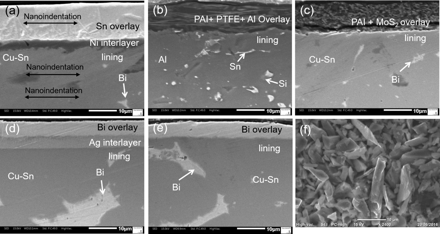
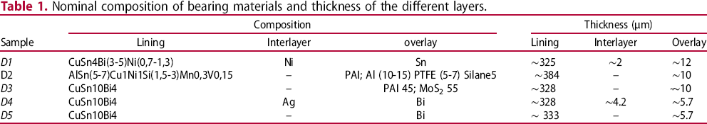
Hardness values for the overlays and linings of the different materials are shown in Figure 2. In general, hardness of the overlay is lower than the lining materials. The metallic overlays show lower hardness compared to the composite overlays. The nanoindentation measurements were carried out on the polished cross-sections of the bearing materials. Indentations were carried out in a row along the horizontal direction as shown in Figure 1(a). At least nine measurements were carried out for each layer and an average hardness value was calculated based on these. The hardness values are not absolute hardness values especially for the overlays since there is some influence from the adjacent layers. In addition, for the composite overlays, the scatter in the hardness is related to the fact that the indentation could be on the metallic particles or the polymer matrix. Moreover, the nanoindentation measurement values in polymeric materials can also be affected by the direction and length of the polymer back chain. For the linings, nanoindentation was carried mainly on the copper-tin matrix to avoid the Bi soft phase in D1, D3, D4 and D5. For the lining of D2 nanoindentation was carried out mainly on the aluminium matrix. But there could be some influence from the soft phase Sn and hard Si particles in the lining. The nanoindentation was carried out using a Micro Materials NanoTest Vantage system in a load-controlled manner with a maximum load of 5mN.
Hardness values of linings and overlays of bearing materials.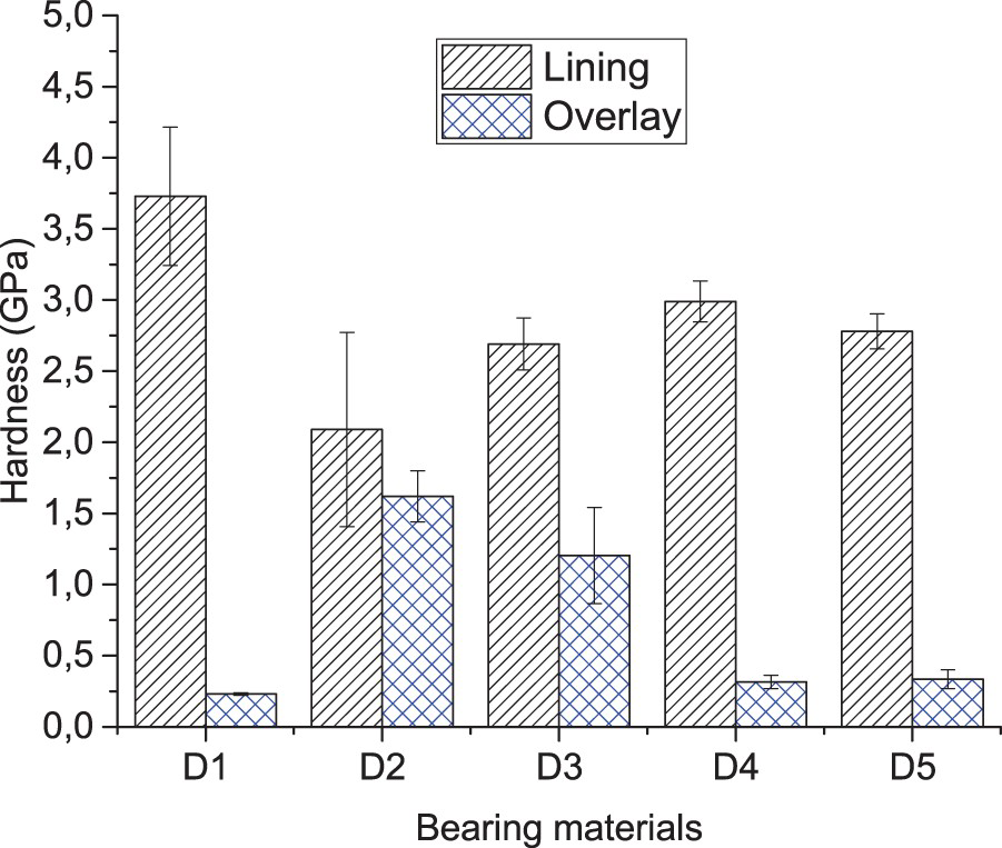
A journal bearing test rig that operates under constant load condition has been employed to investigate the embeddability behaviour of the bearing samples. A simple schematic of the test rig is given in Figure 3. A half bearing shell (Ø108 and 34 mm width) is mounted in the lower section of the bearing housing. The steel counter surface, which is a sleeve with outer diameter Ø107.5 mm and hardness value of ∼610 HV and Ra value of ∼0.2 µm, is mounted onto the shaft that is coupled to the drive motor. The load is applied by placing a dead weight at the end of a lever arm. The bearing housing has freedom of movement to compensate for misalignment. The rotational speed of the shaft has a range from 0 to 1500 rpm. There is an oil tank equipped with a heater and stirrer to continuously mix the SiC abrasive particles in the oil. The oil is supplied into the bearing housing from the oil tank through a pipe. Once the oil lubricates the system it is collected in an oil reservoir located beneath the bearing housing. The oil is then recirculated using a hose pump.
Schematic of the embeddability test rig and a front view of the bearing housing.
Weight loss due to abrasive wear was measured on both the bearing and shaft samples using a weighing balance that reads two decimal places to the right of the decimal point. Two measurements were carried out for each bearing material and the average weight loss values are reported. The weight loss results are average of two tests using new bearing specimens as well as shaft specimens for each test. Surface analysis was carried out to investigate damages on both bearing and shaft surfaces. Scanning electron microscopy (SEM) with integrated energy dispersive spectroscopy (EDS) was used for studying the abrasive wear on bearing materials and counter surfaces. White light interferometry (Veeco Wyko 1100NT) was also used to study topography changes on the counter surface.
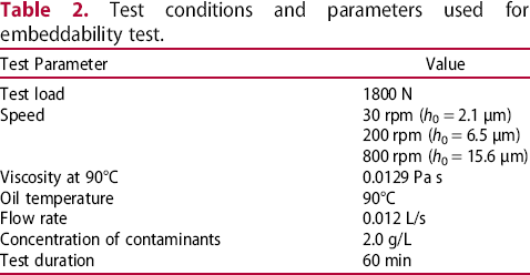
Test conditions and parameters used for embeddability test.
Test conditions and parameters used for embeddability test.
Embeddability behaviour of five different bearing materials was investigated at different minimum film thickness conditions. In this section effect of the minimum film thickness on abrasive wear, weight loss of the bearing and counter surfaces due to abrasive wear and abrasive wear mechanisms are presented and discussed.
Effect of minimum film thickness
Damage due to abrasive wear on the bearing surfaces was found to be high at 200 rpm (h0 = 6.5 µm) compared to those at 30 rpm (h0 = 2.1 µm) and 800 rpm (h0 = 15.6 µm) for the same test duration of 60 min. Figure 4 shows photographs of surfaces of bearing material D4 after tests carried out at 30, 200 and 800 rpm. The damage on bearing materials tested at 800 rpm is considerably lower compared to those tested at 200 rpm. This can be explained by the fact that at 800 rpm the minimum film thickness is large enough to allow free circulation of most of the abrasive particles without causing severe abrasion on the surface. There are scratches on the overlay caused by some particles larger than the minimum film thickness. However, at 200 rpm the overlay is worn out around the middle of the bearing shell which corresponds to the location where the minimum film thickness occurs. At 200 rpm, most of the abrasive particles cannot pass through the interface and hence when the abrasive particles are dragged between the two surfaces the overlay material is gradually worn out and subsequently exposes the intermediate layers. At lower rotational speed of 30 rpm, the number of particles that are fed into the interface is fewer and their velocity is lower since the rotational speed, as well as the total sliding distance, is lower compared with that at 200 rpm for the same test duration of 60 min.
Photograph of worn surfaces of bearing material D4 after tests at three different test conditions.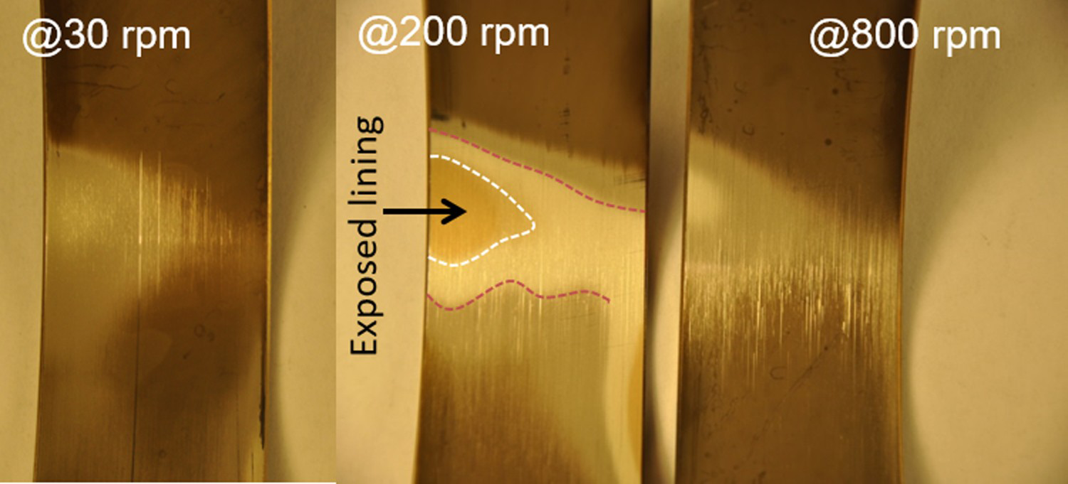
In general, the severity of the abrasive wear varies along the circumferential direction of the bearing surfaces. This is a direct implication of the lubricant film thickness distribution. Away from the minimum film thickness area in the entrainment direction, the film thickness is larger and therefore the numbers of abrasive particles that pass through without causing severe damage are higher. However, as the abrasive particles continue moving forward with the oil in the sliding direction, the gap between the bearing and shaft surfaces becomes smaller to the point where the gap becomes equal with the particle size and hence they cause more scratches and removal of material. Once, the abrasive particles left the minimum film thickness area, the film thickness become larger and hence the number of abrasive particles that can scratch the bearing surface becomes less and less as they move out of the interface.
Figure 5 shows white light interferometry images of part of the counter surfaces sliding against bearing material D4 tested at 30, 200 and 800 rpm. More material was removed from the counter surface sliding at 200 rpm than those sliding at 30 and 800 rpm. At 800 rpm the minimum film thickness is large enough to allow most particles to circulate without causing severe damage on the shaft surface. At 200 rpm, however, the film thickness becomes smaller and the abrasive particles that circulate with the oil can cause abrasion as they are dragged between the two surfaces. In addition, abrasive particles that are partially embedded on the bearing surface abrade the counter surface. At the lower rotational speed of 30 rpm, as shown later in Figure 12, large numbers of these particles are trapped by the overlay before entering the minimum film thickness zone. The trapped abrasive particles cause damage to the shaft.
White light interferometry images of counter surfaces used against bearing material D4.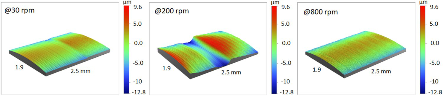
The weight loss due to abrasive wear of the bearing materials tested at three different speeds is shown in Figure 6(a). Although the discussion is based on weight loss of bearing materials, it should be noted that as rotational speed decreases wear rate (gram/meter) increases. The difference in weight loss due to abrasive wear among bearing materials is more visible and easy to compare at 200 rpm than the other two test conditions. D1 which is Sn-based overlay-coated material and D2 which is composite PAI-based overlay containing PTFE and metallic (Al) particles shows lower weight loss than D3 with PAI-based overlay containing MoS2, and D4 and D5 which are Bi-based overlay-coated materials. The Sn-based overlay has slightly lower hardness compared to the Bi-based overlay but both of them can be considered as soft metals. In soft metals, abrasive particles tend to embed without causing severe abrasive wear of the overlay. However, the Bi-based overlay shows significantly higher wear compared to the Sn-based overlay. The main reason for this difference is that the Bi overlay of D4 and D5 are significantly thinner than the Sn-based overlay of D1. The thickness of the Sn-based overlay is about 12 µm but the Bi-based overlay is about 5.7 µm. Considering the size of the abrasive particles which spans a wide range (up to 18 µm) the soft thin Bi overlay can easily be abraded exposing the intermediate layer. However, the thick Sn-based overlay can safely embed the particles and reduce the abrasive wear. On the other hand, the PAI-based overlay-coated materials D2 and D3 show a significant difference in their weight loss. The weight loss is found to be higher for D3 compared to D2. Regardless of the PAI polymeric matrix, there is a difference in their structure. For example, overlay of D2 contains PTFE and metallic particles in a very small amount in the PAI polymer matrix. In contrast, overlay of D3 has a large amount of MoS2 particles in the polymer matrix. In such composite materials in addition to the wear resistance of the polymer matrix, other factors such as the interfacial bonding between polymer matrix and the reinforcement can influence abrasive wear. The volume fraction of the reinforcement in the polymer matrix can also affect abrasive wear [14]. Abrasive wear due to particle removal by the sharp abrasive particles is also possible. The observed high abrasive wear of the PAI-based overlay containing MoS2 particles could be because of these factors. In D3, D4 and D5, once the overlay is entirely worn out the intermediate layers which are harder materials with less tendency of embedding abrasive particles are exposed. These exposed harder layers are then abraded by the SiC abrasive particles. At 30 and 800 rpm, the differences in weight loss among the tested bearing materials are not very significant considering the error associated with the weight measurement. However, the Bi-based overlay plated materials still show slightly higher weight loss compared with the other tested bearing materials.
Weight loss (grams) of (a) bearing materials, (b) shaft specimens and wear rate (grams/meter) of (c) bearing materials and (d) shaft specimens.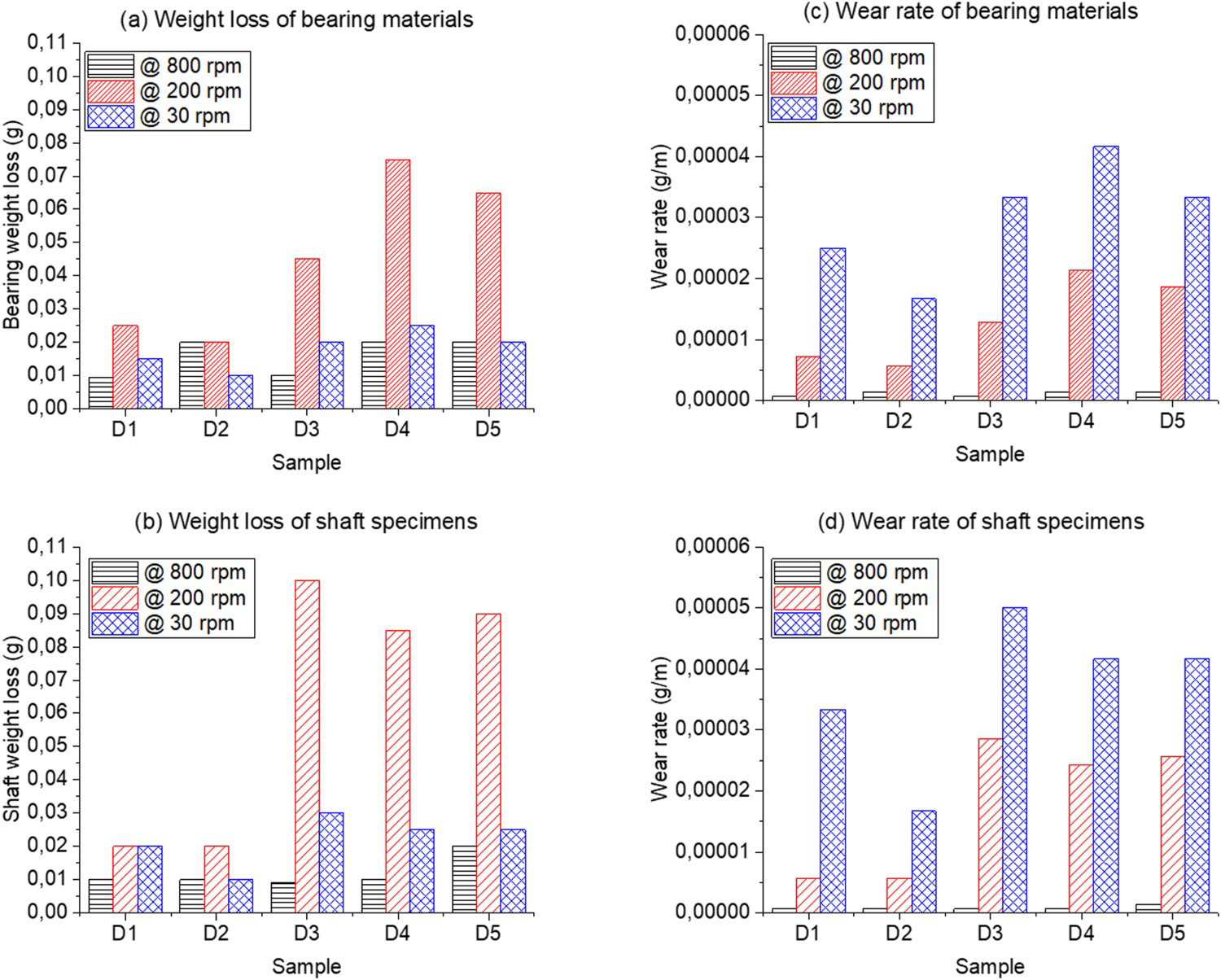
The weight loss of the bearing materials may not be enough to describe the embeddability behaviour since, by definition, embeddability is the ability of bearing materials to minimise damage on the crankshaft by the abrasive particles circulating with the oil. Hence, the severity of abrasive wear on the counter surface is also important in characterising the embeddability behaviour of the bearing materials. Figure 6(b) shows weight loss of the shaft specimens at the three test conditions. At 200 rpm, it is easy to compare the weight loss caused by abrasive wear on the counter surfaces sliding against the different bearing materials. The shaft specimens sliding against D3, D4 and D5 shows higher wear than those sliding against D1 and D2. This is mainly related to the ability of the bearing materials to embed abrasive particles. Those materials that tend to safely (fully) embed and reduce the number of abrasive particles circulating with the oil reduce the abrasive wear on the counter surface. In this regard, D1 and D2 which show the lowest wear also reduce wear on the counter surface.
Figure 6(c,d) shows the normalised wear rate at different rotational speeds for the bearing and shaft specimen, respectively. As rotational speed increases, the minimum film thickness increases and hence the abrasive particles circulate with the oil without causing significant wear.
Mainly two types of damages were observed on the steel counter surfaces. There is a polishing of the shaft surface accompanied by microgrooves as shown in Figure 7(a). This occurs mainly in the counter surfaces sliding against the bearings run at 200 and 30 rpm where the polishing and microgrooves were located on the edge of the rotating shaft. It is most likely more pronounced around these locations because of small misalignment that causes variation of the oil film thickness in the axial direction. According to Williams [8], such damages occur when the dimension of particles to film thickness ratio is above a certain critical value which results in the abrasive particles getting embedded on the softer material (bearing surface) and will spend some time sliding against the harder surface (shaft). In addition, abrasive wear due to indentation and micro-scratches is observed on the counter surface as shown in Figure 7(b). These scratches and the indent marks result in a dented surface. This kind of wear was mainly observed in the shaft surfaces used at 800 rpm where the minimum film thickness is larger than those used at 30 and 200 rpm. Such kind of abrasive wear occurs when the abrasive particles roll or tumble through the lubricant film that separates the bearing and the shaft surface. Detailed image of the micro-scratches and indent marks and materials removed due to micro-cutting are shown in Figure 7(c,d).
SEM images of steel counter surface: (a) shiny surface due to polishing accompanied with microgrooves, (b) micro-scratches and indents, (c) high magnification images of micro-scratches and (d) indents and removed material.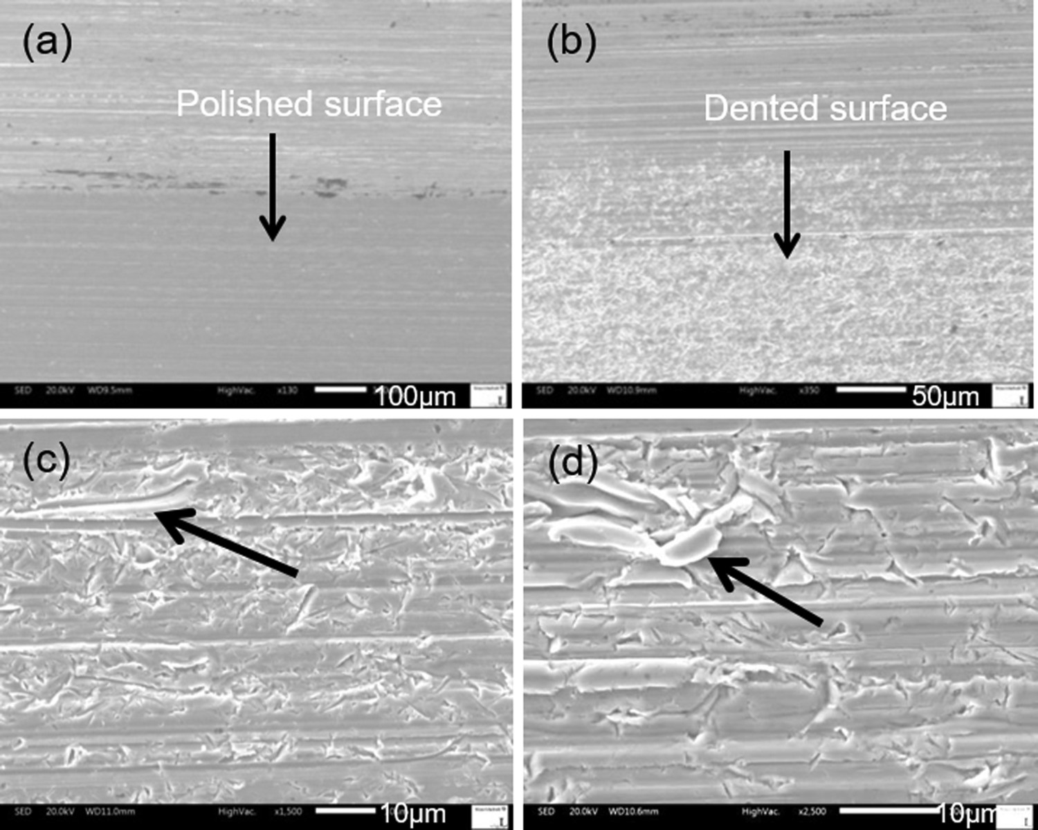
Surface analysis carried out on the tested bearing materials shows different features. In general, abrasive wear increases in severity from the beginning of the entrainment direction towards the location where the minimum film thickness occurs. Figure 8(a–d) shows the differences in the severity of indents and micro-scratches at different locations on bearing material D1 tested at 200 rpm. Figure 8(a) shows the original surface of D1 which is Sn-based overlay. Figure 8(b) shows a smaller number of indents marks and micro-scratches at location far away from the minimum film thickness area. The abrasion is caused by the sharp edges of the abrasive particles. As shown in Figure 8(c) the number of indents and abrasion increases as the gap between the bearing and the shaft surface decreases. The scratches become more severe at the location very close to the minimum film thickness area as shown in Figure 8(d). In this region, the surface is severely abraded and the features observed in the original surface disappear since the space between the two surfaces is smaller and the abrasive particles remove more material from the overlay. This trend is observed in all tested bearing materials in all the three test conditions, however, the extent of severity was highest at 200 rpm where in most cases the lining, which was originally protected by the overlay, is exposed as shown in Figure 4.
Severity of abrasion on bearing surface along the circumferential direction in Sn overlay-coated bearing material D1: (a) original surface, (b) far away, (c) closer and (d) very close to the minimum film thickness area.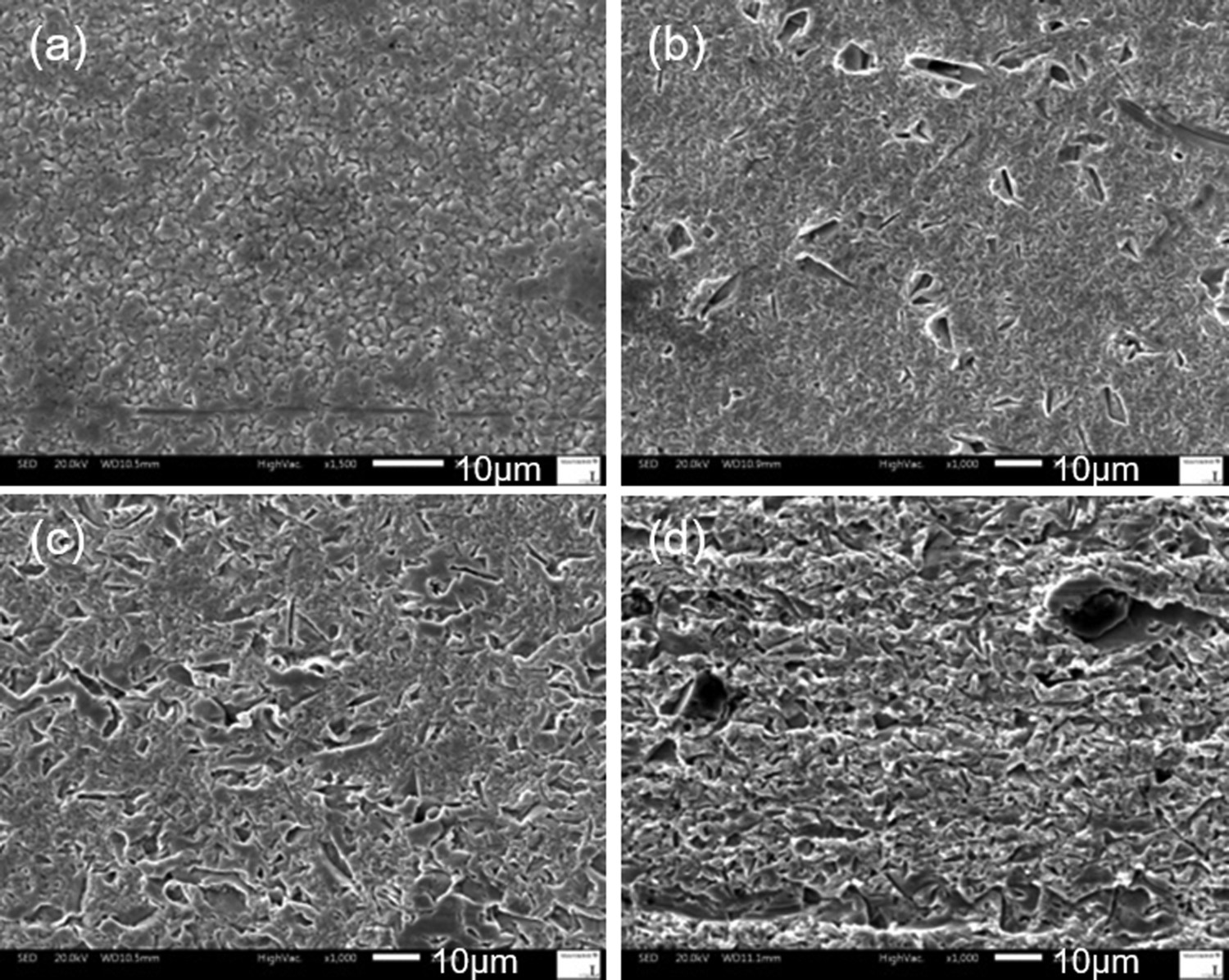
Various forms of damage are observed on the bearing surfaces. Some of the features observed on the bearing surfaces indirectly show the causes of damages on the counter surfaces. The typical damages caused by abrasive particles on bearing materials are discussed in the following section.
In most of the bearing materials, grooves caused by abrasive particles are common on the overlays. For example, as shown in Figure 9(a), in D1 these grooves are deeper and wider than the micro-scratches observed on most of the overlays and exposed linings. They are also relatively long and extend in the sliding direction. This indicates that the abrasive particles that cause these grooves are dragged along the circumferential direction when they are forced to circulate with the oil. Based on the width of these grooves, it is possible to say that they are caused by larger abrasive particles and can also cause abrasive wear on the counter surface. Deep and long grooves caused by abrasive particles are also observed on the composite overlay of D2 as shown in Figure 9(b). The grooves are characterised by displaced material on both sides of the groove. In addition, there are also other patterns associated with the way abrasive particles remove material from the bearing surface while they circulate with the oil. Figure 9(c) shows abrasive wear track on the overlay of D5 left by abrasive particle rolling between the interfaces. Although most of the grooves are observed on the overlays of most materials, there are also grooves caused by abrasive particles on the exposed linings. For example, the SEM analysis of the grooves on the exposed lining region cut out from bearing specimen of D3 is shown in Figure 9(d).
SEM micrographs showing (a) grooves along the circumferential direction on Sn-based overlay of D1, (b) deep groove on the composite overlay of D2, (c) wear track left by rolling abrasive particle on Bi overlay of D5 and (d) micro-scratches and grooves on the exposed lining of D3.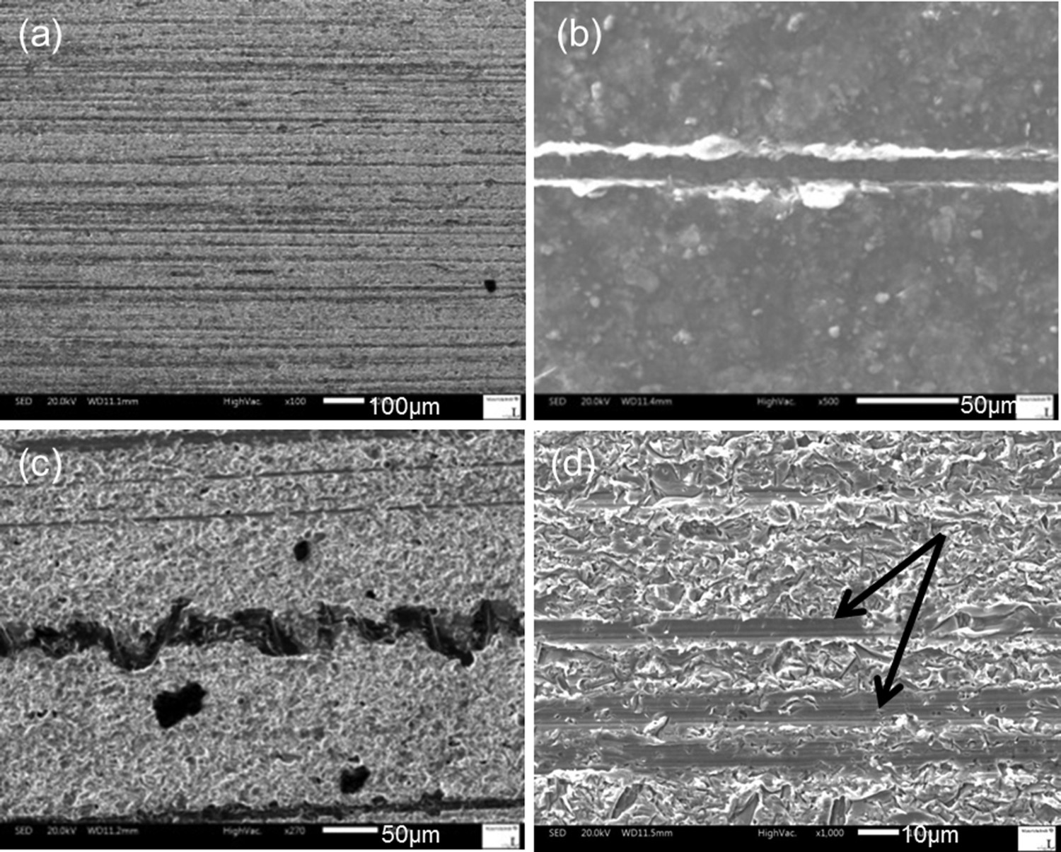
There are also micro-scratches and indents on both the overlay and the exposed linings of most of the bearing materials. Even though the size of the micro-scratches and indents looks small, there is a significant amount of material removed from the surface. In addition to the micro-scratches, there is wear of material as metallic chips by micro-cutting on the overlay of D1 on a location away from the minimum film thickness area at 200 rpm as shown in Figure 10(a). In general, the micro-scratches and indents are less pronounced in locations away from the minimum film thickness area. However, along the circumferential direction more micro-scratches and indents become visible at the minimum film thickness area. The surfaces are also more abraded as shown in Figure 10(b) for the overlay of D2 on locations close to the minimum film thickness area at 30 rpm. In most of the bearing materials, especially at 200 rpm, the overlay is entirely worn out and the lining is exposed. The exposed linings that are located around the minimum film thickness area also suffer damages due to micro-scratches and indents as shown in Figure 10(c).
SEM micrographs showing (a) micro-scratches and chip formation on the overlay of D1, (b) abraded overlay of D2 and (c) random oriented scratches on the exposed lining of D4.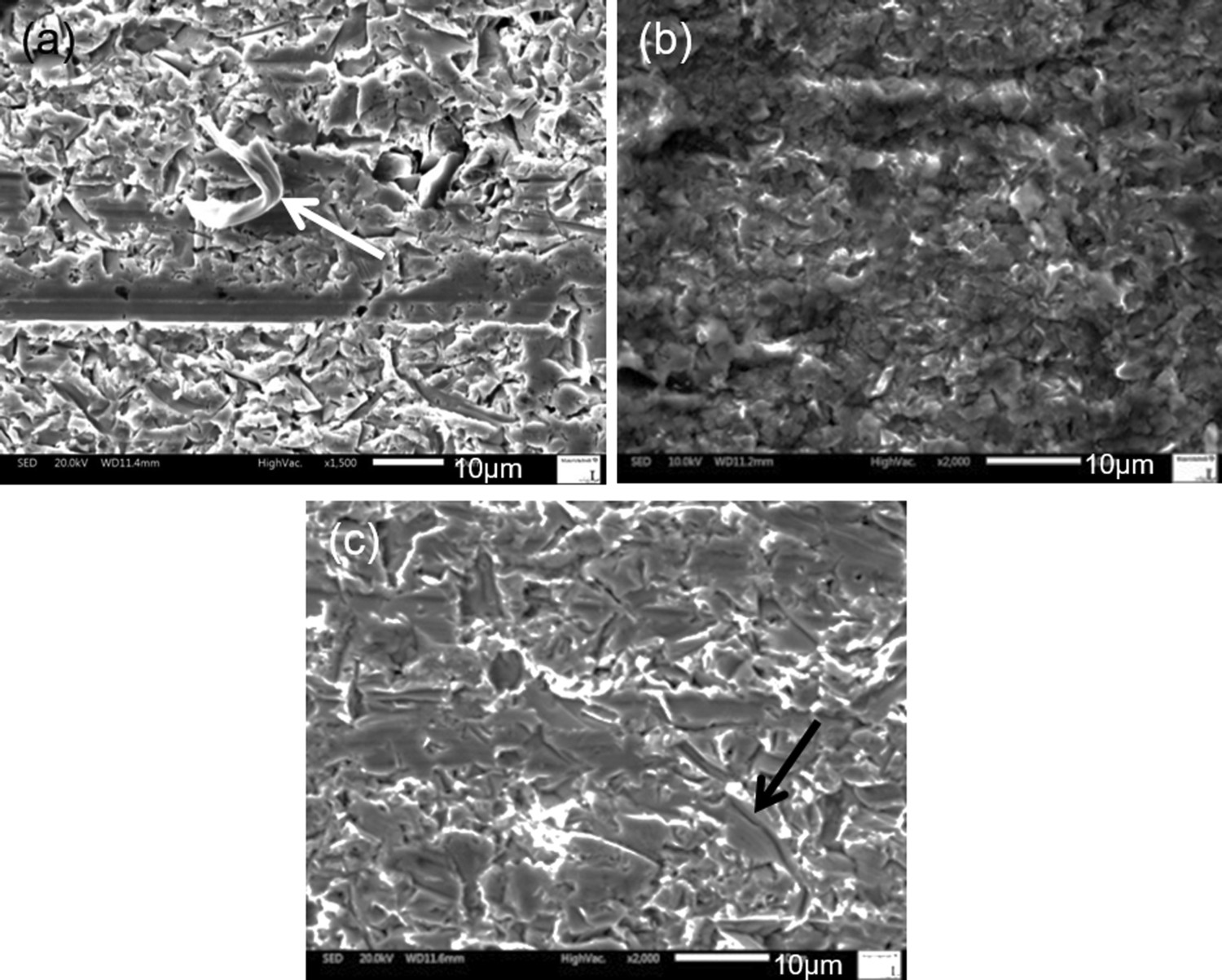
Embedded particles are observed mainly on the overlays of most of the bearing materials. Abrasive particles are embedded on the overlay in two different ways. As shown in Figure 11(a,b), some abrasive particles first scratch the surface and then get embedded. This is confirmed by the grooves they leave behind them. Other abrasive particles get embedded without scratching the surface as shown in Figure 11(c). These abrasive particles are pressed deep into the overlay. This might happen as soon as the abrasive particles enter the area with a gap comparable to their size they are pressed against the overlay by the counter surface. In the metallic overlays, there is pile up of material around the embedded particles due to displace material. Both types of embedded abrasive particles are seen in all bearing materials except in D3. One possible reason for the observed behaviour of the overlay of D3 could be its hardness. The overlay of D3 has a higher hardness than the other metallic overlays. Furthermore, it has a large amount of metallic MoS2 particles in the PAI matrix which may also prevent embedding of particles. Embedded particles are also crushed as shown in Figure 11(d) and are observed mainly in D4 and D5. This happens when a ceramic material such as SiC, which has lower fracture toughness than metallic alloys such as steel, is loaded between the shaft surface and the intermediate layer beneath the overlay.
SEM micrographs showing (a) abrasive particle embedded after scratching composite overlay of D2, (b) abrasive particle embedded after scratching Bi overlay of D4 (c) (c) embedded abrasive particle without scratching Bi overlay of D4 and (d) crushed embedded particle.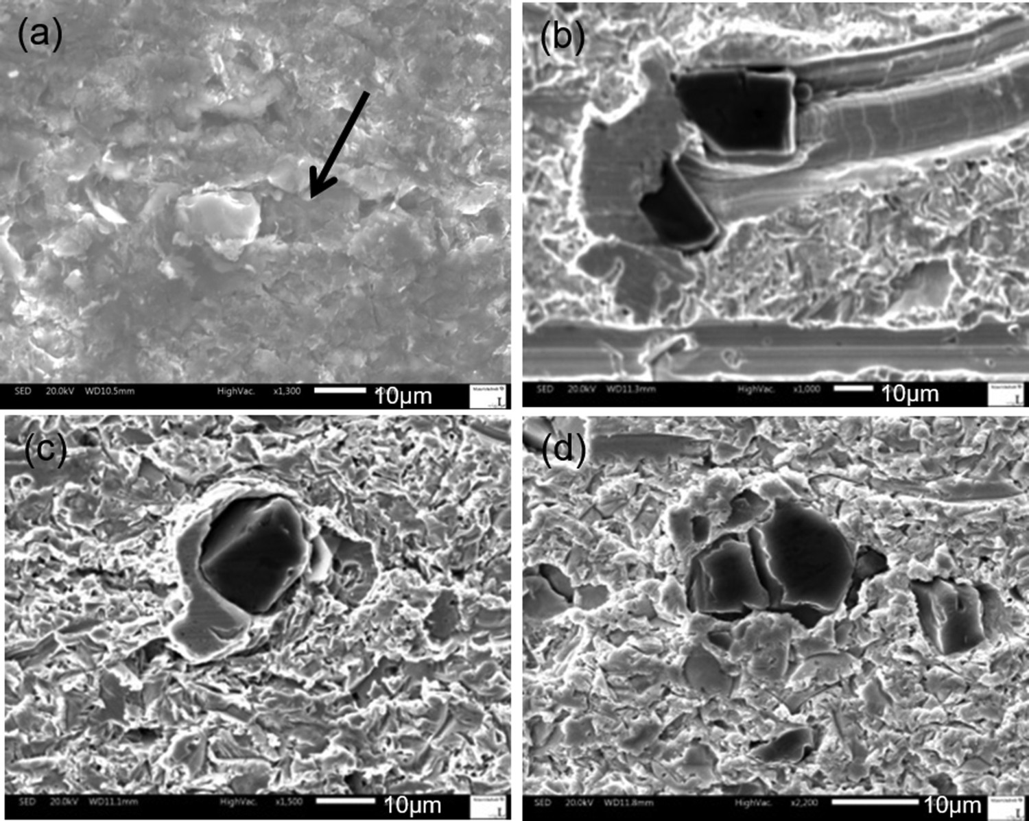
Safely embedded abrasive particles on the Sn-based overlay at 30 rpm and corresponding elemental mapping of the embedded SiC particles are shown in Figure 12(a). Such embedded particles are also observed on the composite overlay of D2 (Figure 12(b)) and Bi overlay of D4 and D5. SiC Particles embedded on the Bi overlay are shown in Figure 12(c). This is an indication that as expected from its low hardness, the Bi overlay can embed abrasive particles; however, its effectiveness depends on both the size of the abrasive particles and the thickness of the overlay since if the abrasive particles are bigger, part of the abrasive particles protrudes from the surface and causes more damage on the shaft specimen.
Embedded particles at 30 rpm and corresponding elemental mapping (a) on Sn overlay of D1 (b) on composite overlay of D2 and (c) on Bi overlay of D5.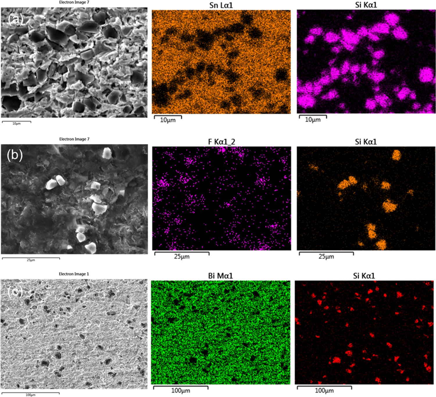
There were partially embedded particles on the exposed lining of D3 as shown in Figure 13(a) even though embedded particles were not observed on its overlay. This is quite different from the embedded particles seen on most of the overlays. The abrasive particles are not fully embedded since the lining is relatively harder than the overlays. Most part of the abrasive particle is protruding out of the surface and can act as hard asperity and causes more damage on the counter surface. Similar features are seen on the exposed lining of D4 and D5. Figure 13(b) shows an abrasive particle that is not fully embedded on the exposed lining of D5. These particles can be big enough to rupture the lubricant film and cause more damage on the rotating shaft. This may contribute to the high wear observed on the steel counter surface sliding against D3, D4 and D5, whose linings are exposed after tests at 200 rpm, and thereby the ability to safely embed hard particles was limited.
SEM micrographs showing partially embedded abrasive particle (a) on the exposed lining of D3 (b) on exposed lining of D5.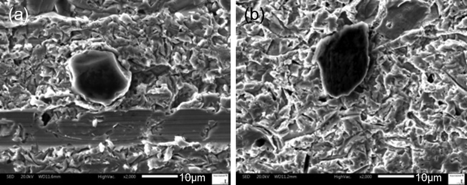
Embeddability characteristics of some Pb-free engine bearing materials have been investigated in the presence of SiC abrasive particles in engine oil and abrasive wear mechanisms were studied.
Third-body abrasive wear of the bearing surfaces and steel counter surfaces is influenced by the minimum film thickness. Abrasive wear was found to be higher on Bi-based overlay and MoS2 containing PAI-based overlay-coated materials compared to the Sn-based overlay and a PAI, Al and PTFE containing composite overlay-coated material. There is a direct relationship between the wear of bearing materials and the wear of shaft specimens tested at 200 rpm. Shaft specimens sliding against bearing specimens that exhibited lower wear shows lower wear and vice versa. Most of the damages on both the bearing and the counter surface involve micro-scratches, ploughing, micro cutting and indents. Abrasive particles are embedded on most of the overlay surfaces except the PAI-based overlay containing MoS2 particles. There are no embedded abrasive particles on the counter surface.
Footnotes
Acknowledgments
The authors would like to thank Scania CV AB for providing test samples and financial support. The authors would also like to thank Dr Mattias Berger from Scania CV AB for his active interest in this work and his helpful feedback.
Disclosure statement
No potential conflict of interest was reported by the authors.