
Abstract
A study was conducted to compare the CAD/CAM method with the conventional manual method in fabrication of spinal orthoses for patients with adolescent idiopathic scoliosis. Ten subjects were recruited for this study. Efficiency analyses of the two methods were performed from cast filling/digitization process to completion of cast/image rectification. The dimensional changes of the casts/models rectified by the two cast rectification methods were also investigated. The results demonstrated that the CAD/CAM method was faster than the conventional manual method in the studied processes. The mean rectification time of the CAD/CAM method was shorter than that of the conventional manual method by 108.3 min (63.5%). This indicated that the CAD/CAM method took about 1/3 of the time of the conventional manual to finish cast rectification. In the comparison of cast/image dimensional differences between the conventional manual method and the CAD/CAM method, five major dimensions in each of the five rectified regions namely the axilla, thoracic, lumbar, abdominal and pelvic regions were involved. There were no significant dimensional differences (p < 0.05) in 19 out of the 25 studied dimensions. This study demonstrated that the CAD/CAM system could save the time in the rectification process and offer a relatively high resemblance in cast rectification as compared with the conventional manual method.
Introduction
Orthotic treatments are generally considered for patients with progressive adolescent idiopathic scoliosis (AIS) with Cobb's angle between 208 and 458 (Wong et al. 2003b, 2000). According to the level of involvement, there are several orthotic designs. For high thoracic curves, the Milwaukee brace is used (Wong and Evans 1998; Lonstein and Winter 1994) while at mid-thoracic or below, Thoraco-Lumbo-Sacral Orthoses (TLSO) such as the Boston brace (Katz et al. 1997); Wilmington brace (Allington and Bowen 1996; Roach and Andrish 1998); or Charleston brace (Federico and Renshaw 1990; Price et al. 1997) are considered. Comparisons of the effectiveness among the different spinal orthoses and other non-operative interventions have been done in some studies (Wong et al. 2003b; Rowe et al. 1997; Focarile et al. 1991). The use of spinal orthoses was found to be the most effective non-operative intervention to AIS.
The conventional manual method of making a spinal orthosis is that a negative body cast is taken from the patient with AIS (Wong et al. 2003a). A positive cast is then prepared by filling the negative cast with plaster. Rectification of the positive cast is done by removing and adding plaster to certain specific areas on the cast. A spinal orthosis is formed by moulding a plastic sheet onto the rectified positive cast. The required trim line will then be cut and straps will be secured to the orthosis. Adjustments to the orthosis would be done during the final fitting.
Computer-aided design and computer-aided manufacture (CAD/CAM) systems have been widely used in the industry since the 1970s (Zeid 1991). In 1979, the first CAD/CAM system for prosthetics and orthotics (P&O) was developed by James Foort and his colleagues at the Medical Engineering Resource Unit of the University of British Columbia. The system was for trans-tibial socket design. Later on, other researchers began to develop different parts of the CAD/CAM system with him. The system was demonstrated at the International Society for Prosthetics and Orthotics World Congress in London in 1983. There was a very positive response leading to a race on the development of commercial CAD/CAM systems. There are about 10 different CAD/CAM systems on the market such as BioSculptor (Finnieston 1997), CAPOD system (Janols 1997), Clynch Technologies Inc. (Reed 1997), IPOS (Kaphingst 1997), Orten (Genevois 1997), Seattle Limb Systems (Dowell and Poggi 1997), TracerCAD system (Pratt 1997), CANFIT-PLUS™ (Mason 1997) and Prosthetics Design Inc. Most studies are related to lower limb prosthetics with few on the clinical application of spinal orthotics.
The clinical practice of the orthotic treatment for AIS was reviewed by the current research team and some drawbacks were pointed out in the conventional manufacture of spinal orthoses such as the time consuming cast rectification, high plaster consumption, and no data storage for future reference. Apparently, the introduction of a CAD/CAM system in spinal orthotics could benefit not only in time saving but also in standardizing the fabrication process, and allowing P&O professionals to spend more time on the patient interface such as education, training and counselling. This study aimed to conduct a scientific comparison between the CAD/CAM method and the conventional manual method in the fabrication of spinal orthoses for AIS.
The objectives of this study
to compare the efficiency of rectification of spinal cast/model modified using the conventional manual method and the BioSculptor CAD/CAM System;
to compare the dimensional difference of spinal cast/model modified using the conventional manual method and the BioSculptor CAD/CAM System.
Materials and methods
This prospective study was conducted in the Rehabilitation Engineering Centre of The Hong Kong Polytechnic University (PolyU) and the Department of Prosthetics and Orthotics, Prince of Wales Hospital (PWH). Ten female patients aged 10 to 14 were recruited from the Scoliosis Clinic of PWH. Their spines were diagnosed with progressive scoliotic deformity with Cobb's angle between 258–458 and curve pattern of right thoracic and left lumbar curves, and orthotic treatment was newly prescribed.
In order to have the same rectification skill, only one orthotist was involved in this study. He had 5 years of clinical experience in treating AIS with spinal orthoses and 3 months experience of using the CAD/CAM method for making spinal orthoses. The casts of the 10 subjects were rectified by the two methods in a tandem approach. Five subjects were randomly assigned to undergo CAD/CAM first and the other 5 subjects to go through the conventional method first. This arrangement aimed to eliminate the learning effect of rectification being carried to the other method in rectifying the same subject.
The CAD/CAM system used in this research study was the BioSculptor CAD/CAM system located in the CAD/CAM laboratory of the Rehabilitation Engineering Centre, PolyU. This system consisted of an Imager (non-contact laser digitizer, see Figure 1), computer station with rectification software and 4.5-axis mill.
Casting and digitization
In the casting process, subjects were lying supine on a hard surface. Plaster of Pairs (POP) bandages were wrapped around the trunk of the subject from the sternal notch to the hip region. Hip joints were flexed to 158 in order to reduce the lumbar lordosis. The negative cast was cut using a wire saw and then removed from the subject.
The sealed negative cast was prepared for digitization (Figure 2). The two ASISs (Anterior Superior Iliac Spines), the mid-point between the PSISs (Posterior Superior Iliac Spines) and lateral vertical mid-line were used as reference points for setting the alignment and orientation of the cast. The casts were scanned horizontally with a resolution of 120 slices and 180 points per slice (data were taken at every 28 of rotation, see Figure 3).
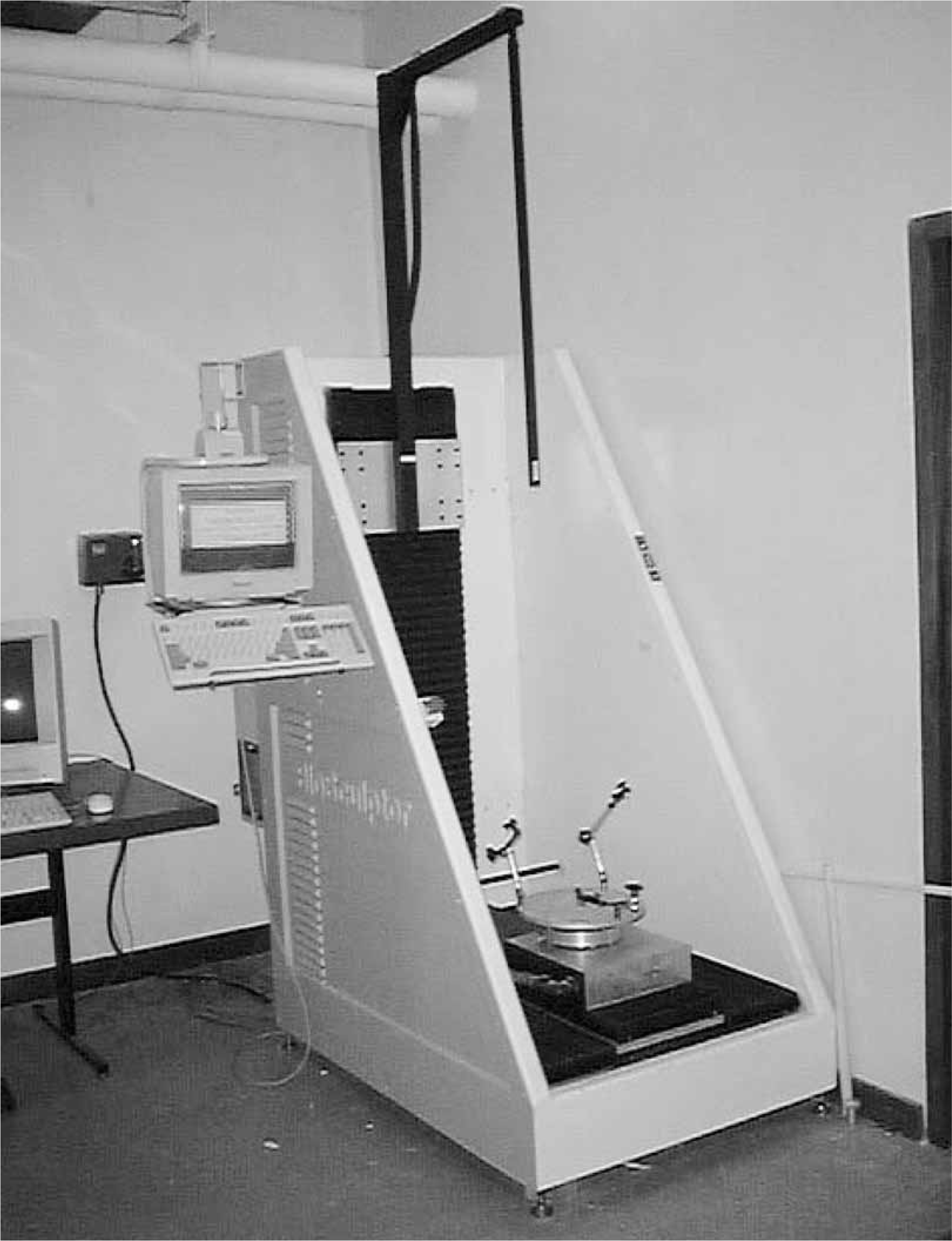
BioSculptor Imager.
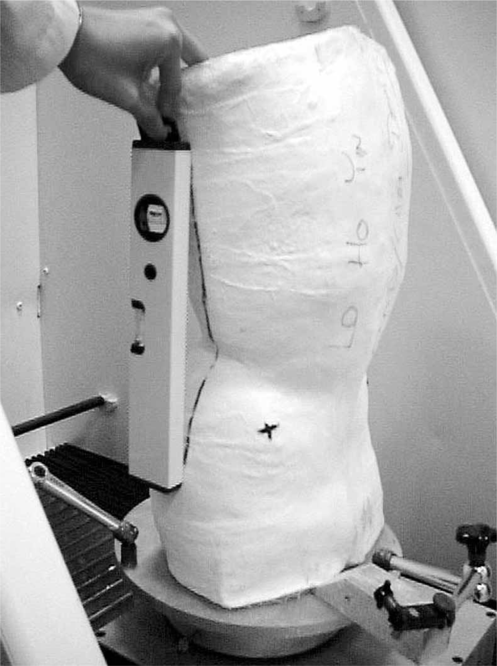
The negative plaster cast is set according to the reference points before digitization.
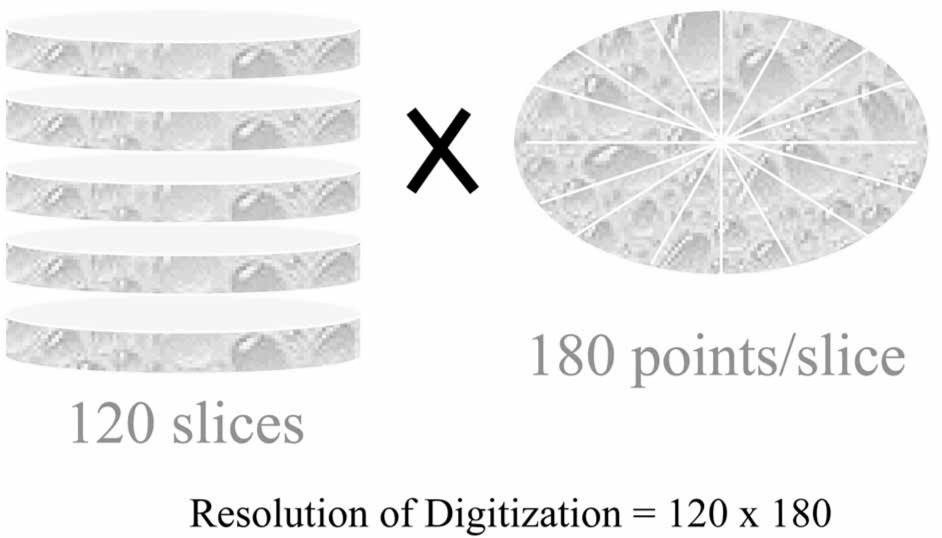
The cast was divided into 120 slices and data were collected at every 28 per slice.
Rectification
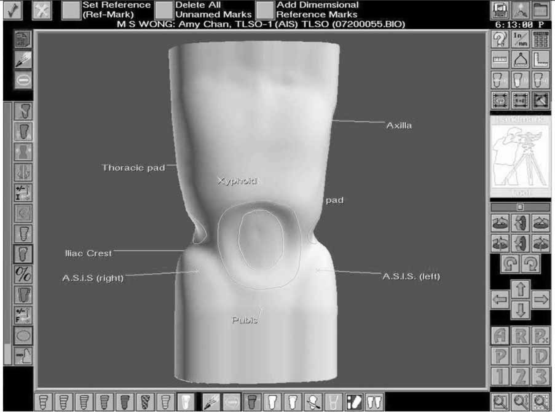
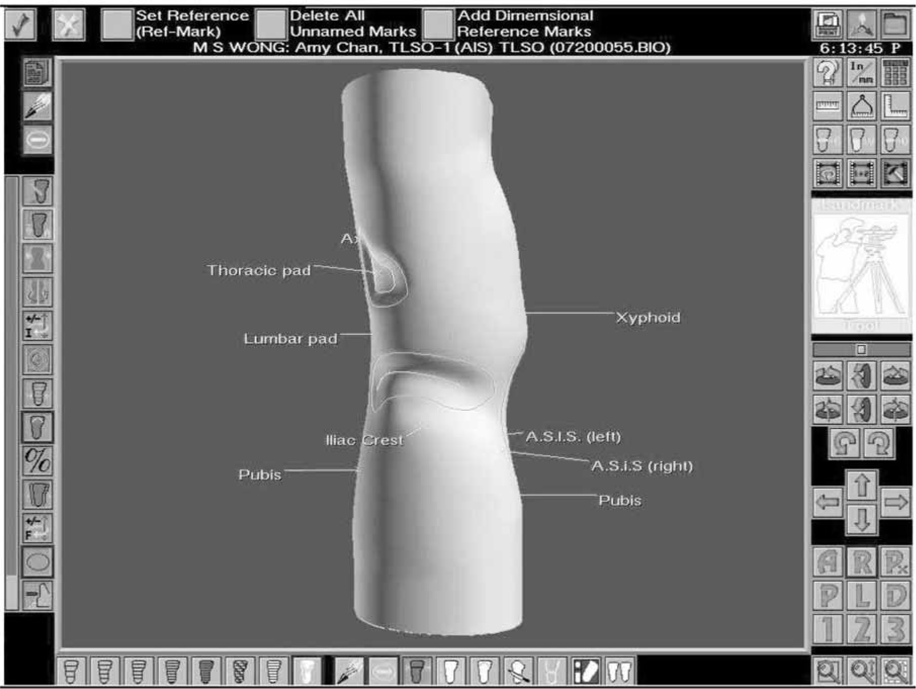
The negative cast was then filled with plaster to make a positive model for manual rectification. Regions were first created by outlining a boundary and then locating the apex line inside the region. The surface contour of the region is related to the position and magnitude of the apex line inside the boundary of the rectified region, and the size of the boundary of the rectified region. There were some major regions for rectification including the pelvic region (anterior and posterior superior iliac spines, iliac crest indentations), and the abdominal region. Pressure (plaster removed) was applied to the abdomen and the region immediately above the iliac crests. Reliefs (plaster added) were provided to the anterior and posterior superior iliac spines, and along the iliac crests. In the design of the orthoses for controlling the scoliotic curvatures, three-point pressure systems in 3 anatomical planes were applied to tackle the 3-dimensional deformity. Pressure/force was created according to the curve apex and curve pattern while pressure relief areas were built correspondingly to allow trunk shifting/curvature reduction. For the CAD/CAM method, the digitized images were rectified using the CAD/CAM software and the principle was the same as that of the conventional manual method but in a 2-dimensional fashion–on the screen of the monitor (Figures 4–7).
Comparison of efficiency of cast rectification
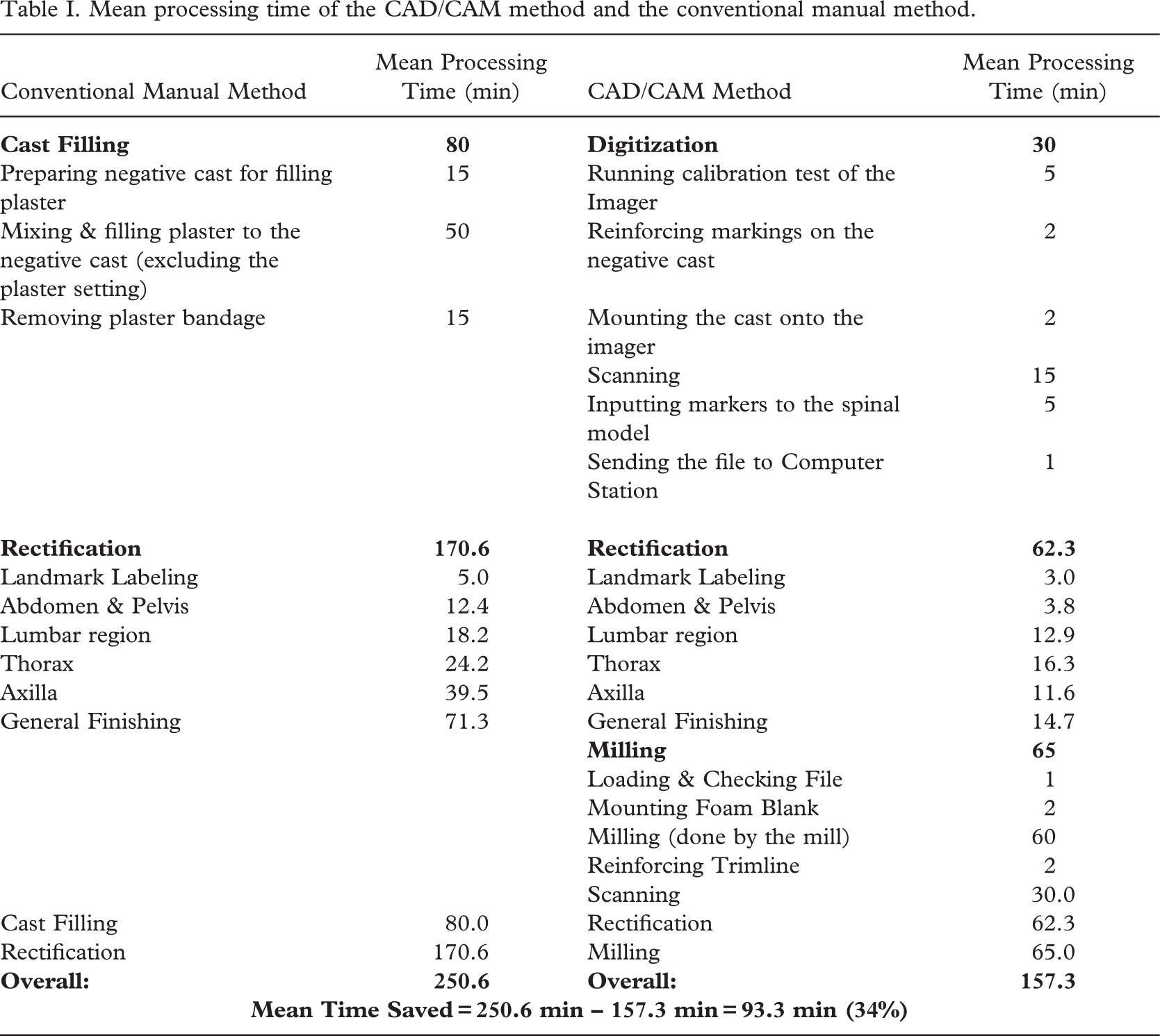
The mean processing time taken from the cast filling/digitization to the completion of rectification/milling and the mean processing time required for the sub-processes (managing the landmark labeling, abdominal and pelvic region, lumbar region, thoracic region, axilla region, and general surface finishing) of the corresponding methods were studied.
The anterior view of the rectified image.
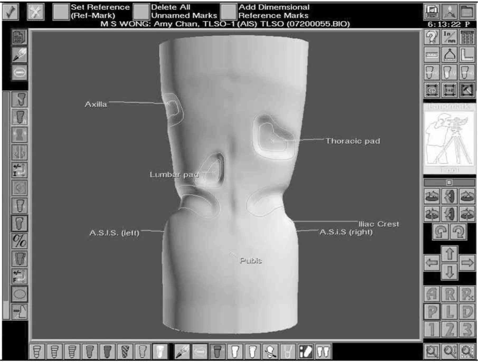
The posterior view of the rectified image.
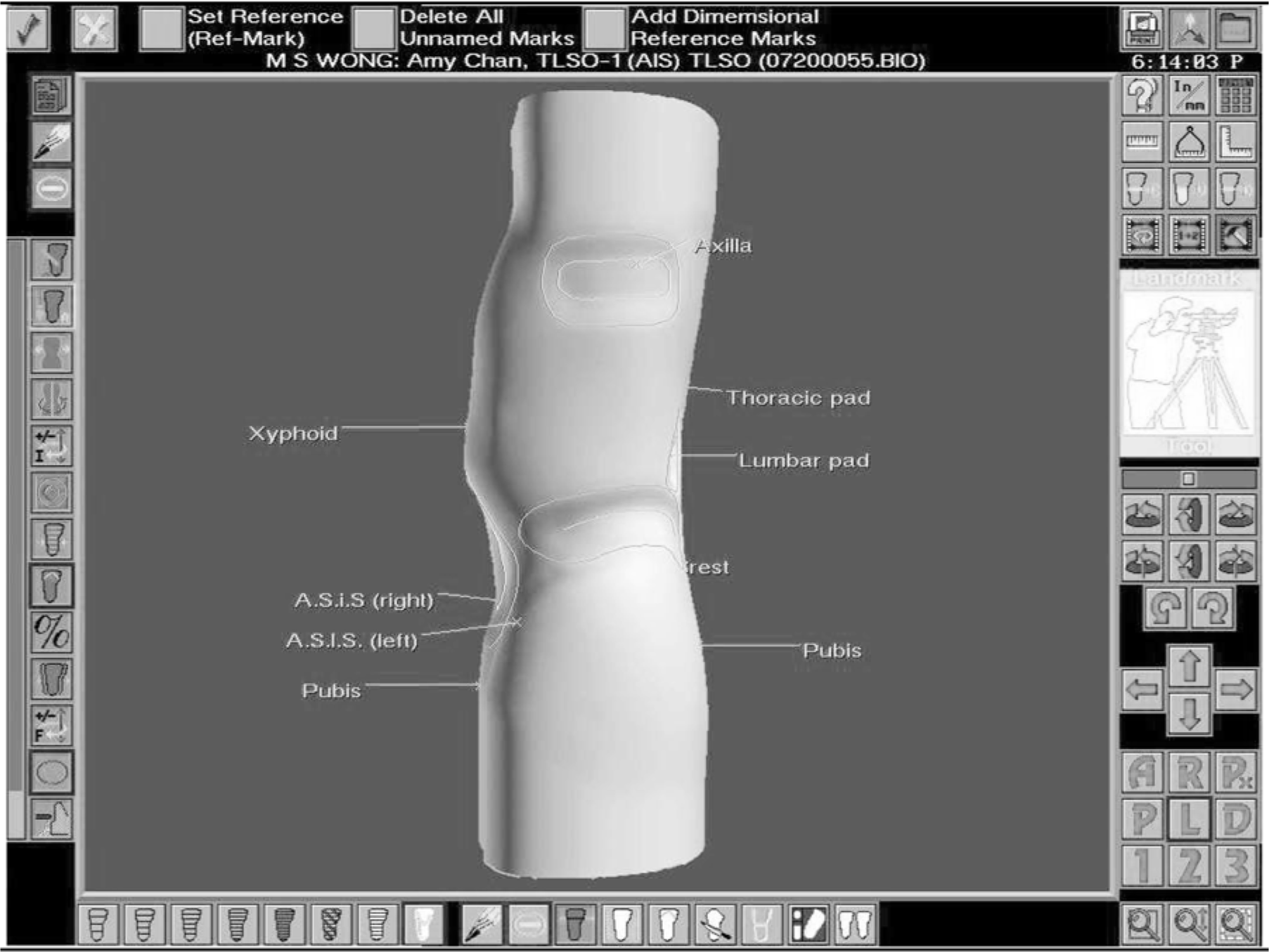
The left side view of the rectified image.
The right side view of the rectified image.
Comparison of dimensional difference of rectified cast
A rectification chart was used to record the locations of the rectification at different regions of the cast. The 10 positive casts rectified by the conventional manual method were sent back to the CAD/CAM system for digitization. The casts rectified by the two different methods were then compared geometrically using the CAD/CAM software.
The geometrical differences of the manual image (as a control for comparison) digitized from the positive cast rectified using the conventional manual method and the CAD/CAM Image rectified using the CAD/CAM method were compared with reference to the five main regions, namely the pelvis, abdomen, lumbar spine, thorax, and axilla. For each region, the dimension of the following 5 parameters was considered:
HA=Vertical height of the apex
DA=Depth of the apex
AA=Angular orientation of the apex on the transverse plane
HR=Vertical height of the region
WR =Horizontal width of the region.
Method of data analysis
The data were analyzed using the Statistical Package for Social Sciences (SPSS) Version 10.0. Paired samples t-tests were used to compare the time used in the two cast rectification methods, and to compare the geometrical difference between the two rectification methods. The level of significance was set at 95% (p < 0.05).
Results
Ten subjects were recruited to compare the efficiency of the cast rectification between the conventional manual method and the BioSculptor CAD/CAM System in the design of spinal orthoses. Their mean age at the diagnosis of idiopathic scoliosis was 12.9 years (10.6–14.4, SD=1.03) and the mean Risser's sign was 1.1 (0–2, SD=0.4). The average age of menarche was 12.3 years (10–14, SD =1.28). The average body height was 153.6cm (141.2–165.8, SD=7.6). The average body mass was 38.9kg (27.1–50, SD=7).
All of the subjects had right thoracic and left lumbar curve pattern. The mean Cobb's angle of the thoracic curves was 27.1° (18°–41°, SD=7.5°) and the mean Cobb's angle of the lumbar curves was 25.2° (15° −43°, SD=9.1°).
Comparison of efficiency of cast rectification
The results of comparison of efficiency of the cast rectification between the conventional manual method and the CAD/CAM method in the fabrication of spinal orthoses are shown in Table I. It was found that from cast filling to completion of cast rectification, the mean reduction of time was 93.3 min (34%) if the CAD/CAM method was used.
If the comparison of the cast rectification was divided into sub-processes namely managing the landmark labeling, abdomen and pelvis, lumbar region, thorax, axilla, and general surface finishing. It was found that there was significant reduction (p < 0.05) in the time used in the rectification of the abdomen and pelvis, the general finishing, and the whole process. The results are shown in Table II.
The results demonstrated that the CAD/CAM method was faster than the conventional manual method. According to the data analysis, the mean rectification time of the CAD/CAM method was shorter than that of the conventional manual method by 108.3 min (63.5%).
Comparison of dimensional difference of rectified cast
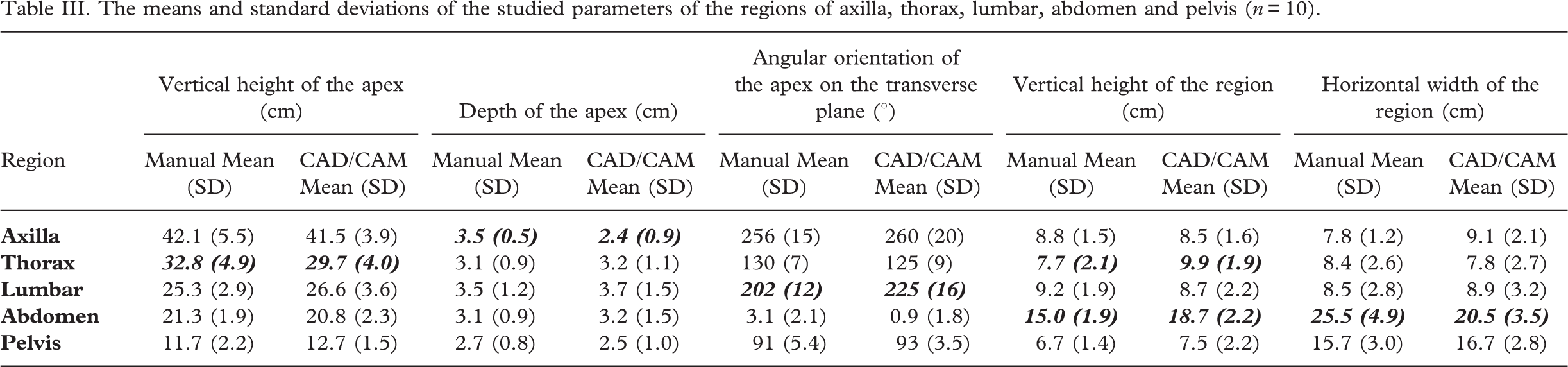
The geometrical data of the rectified casts prepared by the manual method and the CAD/CAM method were compared. The mean and standard deviation of the studied parameters for the regions of upper thorax, thorax, lumbar, abdomen and pelvis rectified by the two methods are shown in Table III.
It was found that in the comparison of the five dimensions in each of the five different regions, there were no significant dimensional differences (p < 0.05) in 19 out of 25 dimensions between the manual images and the CAD/CAM images (Table IV).
Mean processing time of the CAD/CAM method and the conventional manual method.
Comparison of the mean processing time of the sub-processes of the rectification of the CAD/CAM method and the conventional manual method
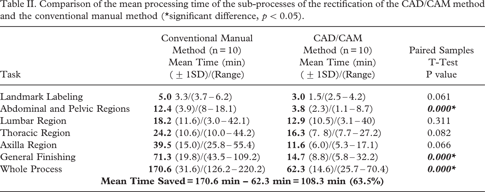
significant difference, p < 0.05
The means and standard deviations of the studied parameters of the regions of axilla, thorax, lumbar, abdomen and pelvis (n= 10).
Comparison of the dimensional difference of the five studied regions between the manual image and the CAD/CAM image.
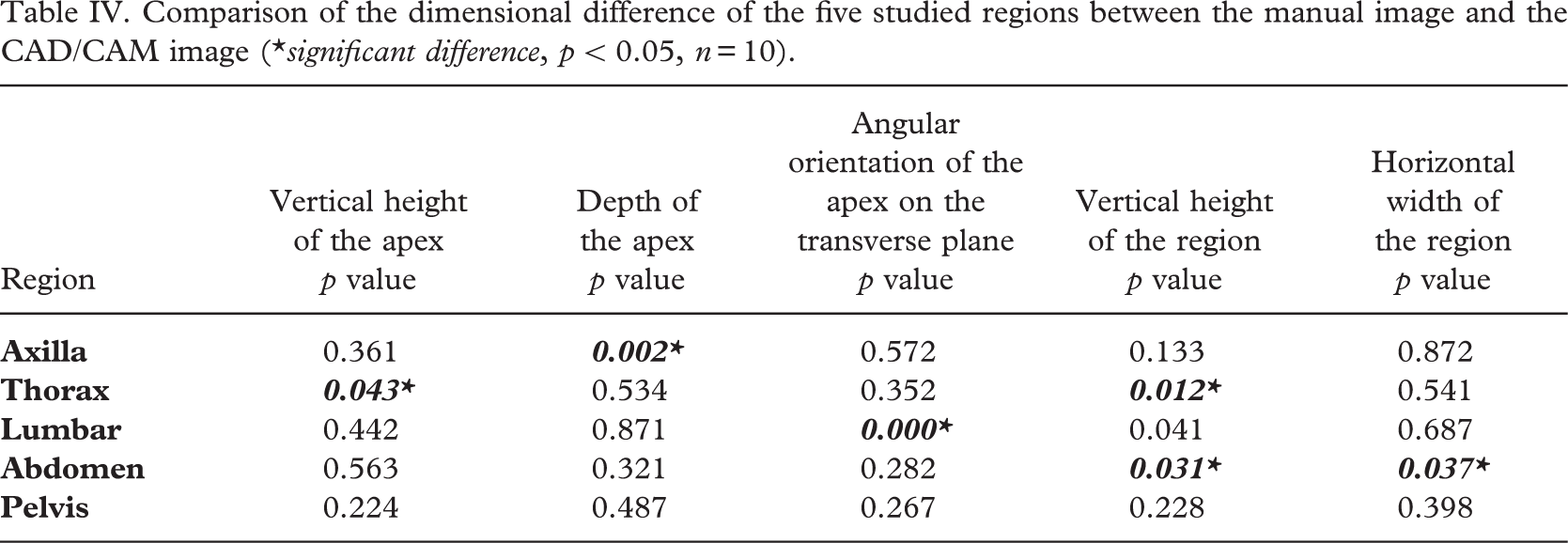
significant difference, p 50.05, n= 10
Discussion
Comparison of efficiency of cast rectification
In the rectification process of the body cast/image such as surface smoothing and building up of the sacrum pad, the use of the CAD/CAM method was shown to give a significant reduction of time in comparison with that of the conventional manual method. In the consideration of the process from the cast filling/digitization to completion of cast rectification/milling, the mean reduction in time was 93.3 min (37.2%) if CAD/CAM method was used. The accumulated reduction of time in each sub-process would lead to significant reduction in the overall time. It was found that the mean overall time (62.3 minutes) of the CAD/CAM method was significantly reduced as compared with the mean overall time (170.6 minutes) of the conventional method. This meant that the CAD/CAM method took only about 1/3 of the time of the conventional manual method to finish cast rectification. If the participating prosthetist-orthotist is more familiar with the CAD/CAM system (reaching a steady state of the learning curve), the rectification time can be even shorter as the prosthetist-orthotist in this study had only 3 months of experience in using the CAD/CAM system.
Comparison of dimensional difference of rectified cast
Traditional training of prosthetist-orthotists is focused on manual rectification. The positive plaster casts were touched and rectified directly. A small ridge or depression could be felt by direct contact with the cast. Beginners with the CAD/CAM system would experience a quite different method of rectification. The 2-dimensional screen cannot display in the same way as the 3-dimensional real object. The contour or texture of the cast/model displayed on the monitor of the CAD/CAM system would depend on how the monitor could show the image and the display resolution. The rectification technique of the CAD/CAM system could be difficult for beginners as they might have to imagine the topography and dimensions of the rectified regions in order to acquire the desired results using CAD/CAM system. Beginners might easily get accustomed to the size of the region, height of the apex, location of the apex, etc. However, the topography of the region could be more difficult to create and manage. In the first three cases of this study, manual rerectification was necessary after the milling process (Figure 8). This close-loop learning process could allow the beginners to assess their own rectification skill and take remedial action when necessary.
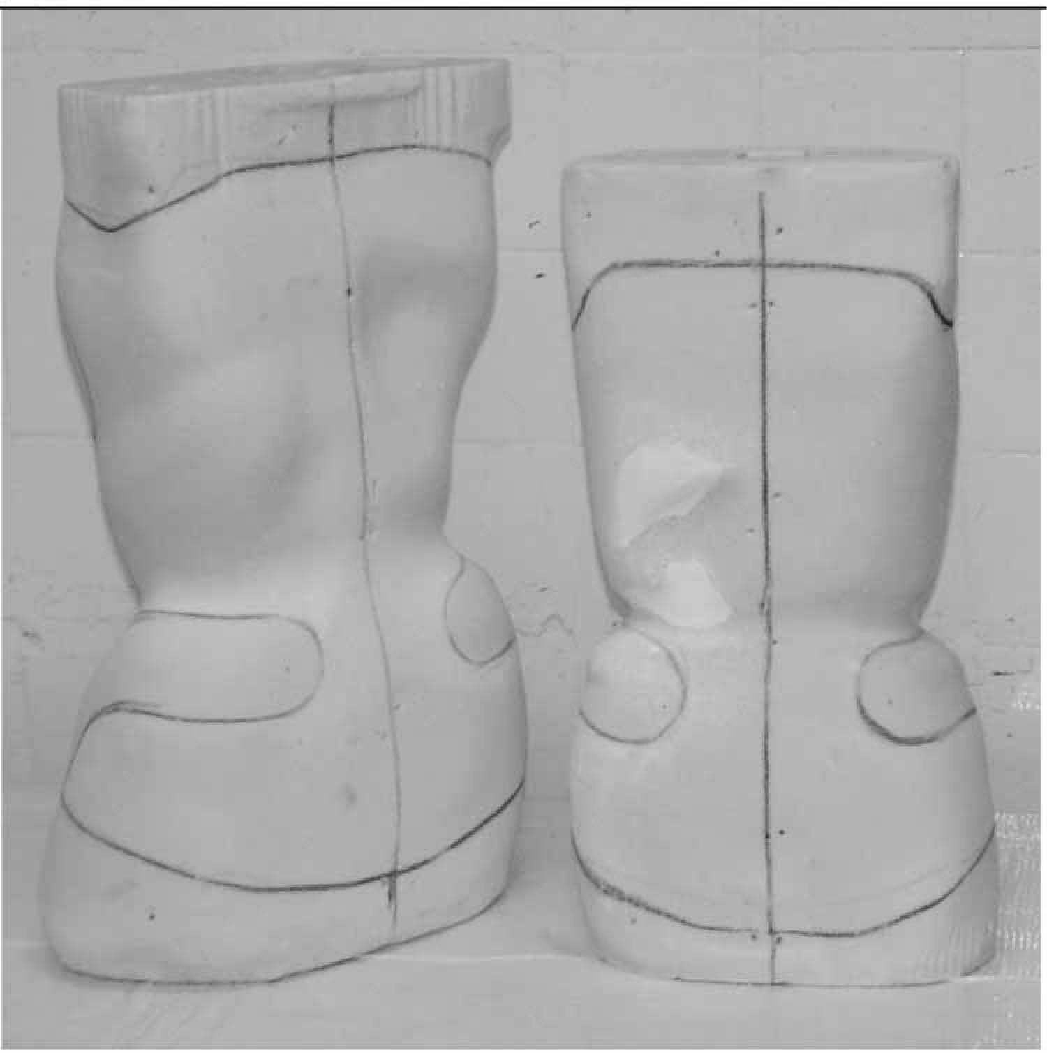
The foam model on the right was re-rectified manually by adding plaster to the left lumbar region.
In this study, the 25 dimensions (5 dimensions per region for 5 regions) were compared between the CAD/CAM method and the conventional manual method. It was found that there were no significant differences in 19 out of 25 dimensions while the remaining 6 dimensional differences might be due to measurement errors and inexperience in using the CAD/CAM method. When the participating orthotist becomes familiar with the CAD/CAM system, the condition could be improved. In general, there were no significant differences in the dimensions of the casts/images rectified using the two methods.
Conclusion
This study demonstrated that the CAD/CAM system could save time in the rectification process and had a high level of resemblance in cast rectification as compared with the conventional manual method. Despite the fact that some minor manual re-rectifications might be required by the beginners in the first few cases, the CAD/CAM system could provide a relatively reliable and efficient tool for orthotists to carry out their clinical duties. To understand the whole picture of application of CAD/CAM system in controlling adolescent idiopathic scoliosis, the clinical effectiveness of the spinal orthoses made from the CAD/CAM system should be fully evaluated in a future study.