
Abstract
This work deals with experimental characterisation of ultra-high-temperature ceramic materials for aerospace applications. Current research activities are focused on development and testing of new-class ultra-high-temperature ceramic matrix composites for near-zero ablation Thermal Protection Systems and near-zero erosion rocket nozzles. To investigate materials behaviour in atmospheric re-entry conditions, relevant tests are carried out on samples with different shapes with a supersonic arc-jet facility, with specific total enthalpies higher than 20 MJ kg−1 and temperatures over 2000 K in a gas atmosphere with high concentration of atomic oxygen. The Aerospace Propulsion Laboratory allows investigating rocket components or subsystems manufactured in innovative materials, such as nozzles and nozzle inserts, but also small specimens exposed to the rocket exhaust plume, in highly relevant operating conditions. Computational models for numerical simulations of high-enthalpy flows, in both arc-jet and propulsion environments, and thermal analyses of the material samples are developed to support the experimental activities.
Keywords
Introduction
Ultra-high-temperature ceramic (UHTC) materials are gaining an increasing importance in aerospace research, because of their high temperature resistance, which makes them suitable for components that have to withstand extremely demanding environmental conditions, such as the ones experienced by thermal protection systems for re-entry vehicles or components for space propulsion [1-3]. The fluid-dynamic phenomena involved in hypersonic flow typical of re-entry vehicles include intense shock waves forming in front of the nose tip and of the wing leading edges of the spacecraft. These shock waves cause the temperature to rise up to thousands of Kelvin and activate gas dissociation/recombination surface reactions. On the other side, rocket environment is characterised by pressure levels up to tens of bar and temperatures over 3000 K, in presence of reactive chemical species. The combination of high velocity and thermo-chemically aggressive environment of the flow passing through the discharge nozzles can lead to chemical and mechanical erosion, in particular in the throat inner section, where heat fluxes and shear stresses reach their peak values [46]. The unique set of properties of UHTC materials allow them to survive the extreme environments encountered in the aforementioned space applications [79].
UHTC materials generally include transition metal diborides and carbides (i.e. ZrB2, HfB2, ZrC, HfC, TaC). The applications of single phase materials, i.e. without secondary phases, are though limited by characteristics such as vulnerability to oxidation attack, insufficient fracture toughness and low thermal shock resistance and lack of damage tolerance. Poor reliability of large UHTC components appeared to be a major issue, also causing failures in high-enthalpy flows. Current research activities are thus focused on ultra-high-temperature ceramic matrix composites (UHTCMC) materials based on C or SiC fibres in UHTC matrices, that represent the next step to gain significant improvements in comparison to the state-of-art materials for aerospace applications [10-13].
In the framework of H2020, University of Naples ‘Federico II’ (UNINA), in collaboration with several European Universities, Research Centres and Industries, is involved in C3HARME research project, focused on the development of a new class of UHTCMC for near zero-erosion rockets nozzles and near zero-ablation thermal protection systems. The project foresees a 4-year plan of research activities, aimed at introducing innovative material solutions and optimising standard processing techniques in order to manufacture final products suitable for space applications.
The University of Naples contributes to the definition of the requirements and is responsible for the prototypes design and the identification of the corresponding testing conditions. Extensive experimental campaigns are carried out on materials prototypes, based on an incremental approach, and supported by numerical modelling and simulation.
This article presents the activities performed so far, including some preliminary experimental results and a description of numerical models for the simulation of high-enthalpy flows for both propulsion and hypersonic re-entry environments.
Experimental characterisation of ceramic materials
A hypersonic arc-jet plasma facility allows characterising materials simulating supersonic atmospheric re-entry conditions, whereas a lab-scaled hybrid rocket and a versatile test rig are available for testing materials and components response in combustion environment. Facilities and set-up of testing are presented below.
Aerothermodynamics
A continuous, open-circuit arc-jet wind tunnel is available at the UNINA Department of Industrial Engineering, in Naples, for the simulation of atmospheric re-entry flows. The plasma is generated by an industrial torch with a maximum power of 80 kW, able to operate with inert gas (He, N2, Ar) at mass flow rates up to 5 g s−1. In order to simulate the air composition, a mixer downstream the torch is used to supply oxygen to the primary nitrogen plasma. A converging–diverging nozzle accelerates the high-enthalpy flow to a nominal Mach number of 3. Specific total enthalpies, estimated at the exit of the torch and at nozzle exit by means of an energy balance, above 20 MJ kg−1 are achieved at gas mass flow rate of 1 g s−1. The specimen in the test chamber can be observed thanks to infrared and optical windows. The facility is provided with a two-colour pyrometer and thermocameras for non-intrusive temperature measurements.
The arc-jet facility has been utilised to test specimens with different shapes and sizes (flat, hemispherical, leading edges with wedge shape) in a relevant atmospheric re-entry environment [14-23]. Each test, whose duration is in the order of 1–10 minutes, is typically performed increasing the total enthalpy of the flow with several steps, corresponding to increasing torch arc power, leading correspondingly to an increase of temperature and pressure. When the maximum total enthalpy is established, a quasi-constant, maximum value of the sample temperature is reached. For a mass flow rate of 1 g s−1, at the maximum enthalpy level, flow temperatures above 5000 K and pressures in the order of 10 kPa are achievable, for maximum wall heat fluxes which can exceed 10 MW m−2, depending on sample geometry and surface properties (catalycity, emissivity) of the material under testing.
In the framework of the current research activities, the prototypes for the experimental campaign are designed according to an incremental approach, proposing to start testing samples of simple shape and increasing the complexity up to a Technology Readiness Level (TRL) 6. Arc-jet testing includes experimentation on small specimens (dimensions in the order of 1 cm), with TRL up to 4, in a relevant atmospheric re-entry environment, Figure 1(a). Various characterisations will allow identifying the most promising material compositions and manufacture processing, before starting experimental activities on larger and more complex geometries (Figure 1(b,c)).
Design of prototypes to be tested in arc-jet facilities in C3HARME project.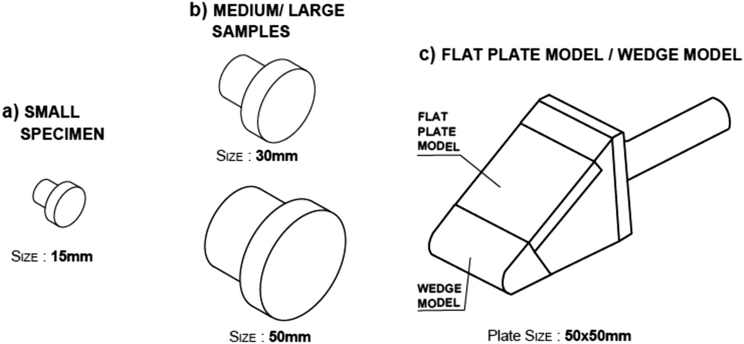
Preliminary tests have already been carried out on button-like specimens. Figure 2(a) shows a picture of a typical test at the UNINA arc-jet facility, with an intense and clearly visible shockwave forming in front of the sample, which assumes a shape similar to the Greek letter λ, due to the interaction between normal shockwave and expansion waves forming around the sample sharp edges. The λ-structure of the shock can be accurately predicted by the computational fluid dynamic (CFD) solution depicted in Figure 2(b), representing the distribution of static temperature obtained employing the numerical models that will be described in Section ‘Numerical models and simulations’. Finally, Figure 2(c) shows a picture taken during a preliminary test performed in DLR arc-jet facility L2K in Cologne, corresponding to a specific total enthalpy of 5.1 MJ kg−1 with a gas mass flow rate of 50 g s−1.
(a) Picture of a test at UNINA arc-jet facility, (b) CFD solution of the temperature field around test article, (c) Picture of a test in DLR L2 K facility, in Cologne.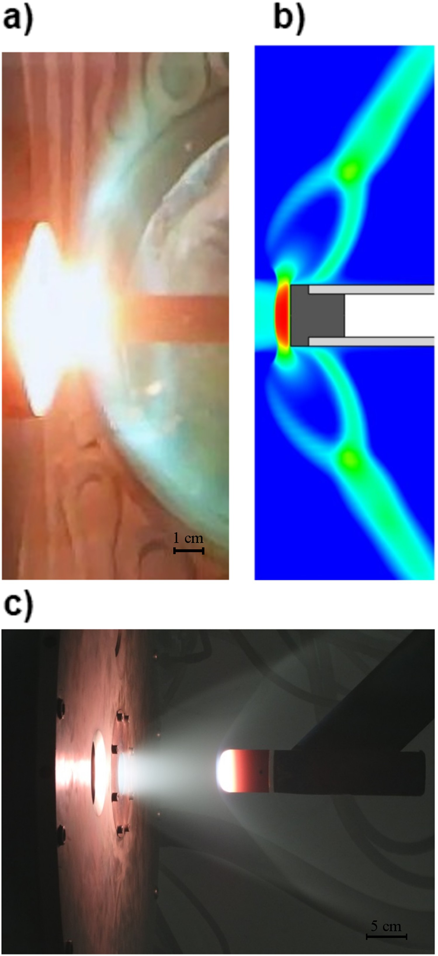
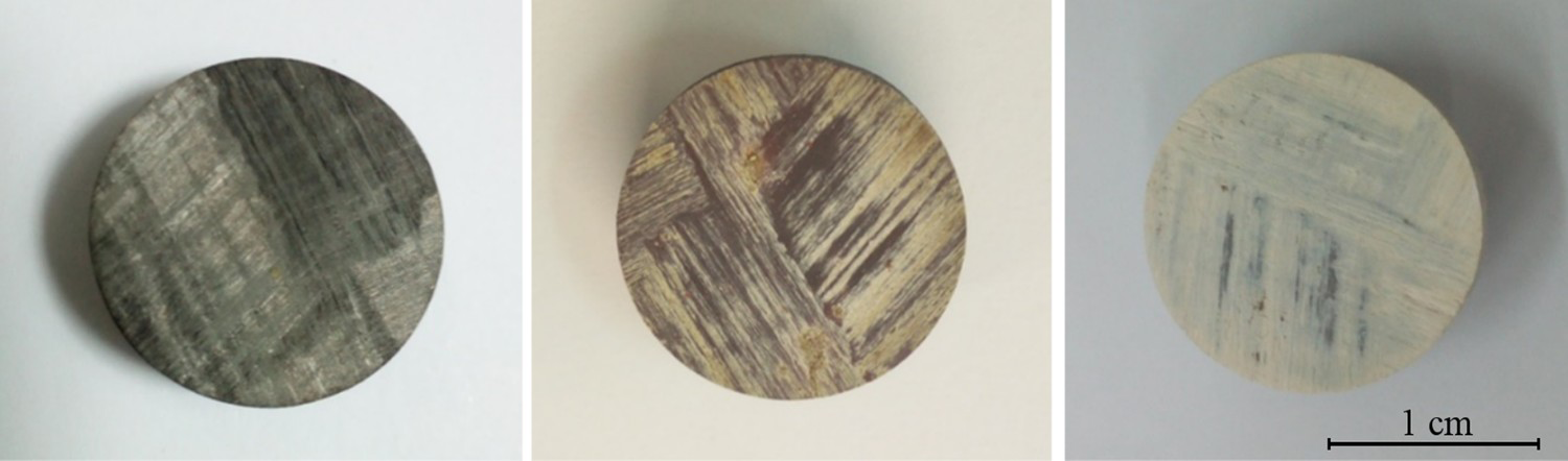
Following, two experiments with increasing enthalpy levels, carried out on a UHTCMC sample made of Carbon fibres in a ZrB2–SiC matrix, are presented. Mass flow rate was 1 g s−1, with a nitrogen mass fraction of 0.8 and an oxygen mass fraction of 0.2, to reproduce Earth atmosphere composition. The specimen's surface temperature was measured by means of a pyrometer (Infratherm ISQ5, Impac Electronic GmbH, Germany) and an infrared thermocamera (Pyroview 512N, DIAS Infrared GmbH, Germany). The thermal history of the maximum surface temperatures of the specimen, which exceeded 2000 K, are shown in Figure 3. The pyrometer two-colour operation mode allowed recording the actual temperature vs time of the specimen. The temperature profile of the thermocamera presented in Figure 3 was calculated setting a spectral emissivity of 0.75. The comparison between the measurements of the two instruments (which operate in the same wavelength band, around 1 μm), which do not completely overlap, made possible an estimation of the spectral surface emissivity of the UHTCMC material, which appears to be decreasing during Tests 2, possibly due to the surface oxidation that occurred at higher temperature. This is clearly visible in Figure 4, which shows the sample before and after the two tests. The specimen got the characteristic whitish coloration, due to the surface modifications.
Thermal histories of the specimens’ surface temperature vs time during the tests. The temperature profiles of the thermocamera are obtained in the hypothesis of a spectral emissivity of 0.75. UHTCMC specimen before exposition to arc-jet flow (left), after Test 1 (centre), after Test 2 (right).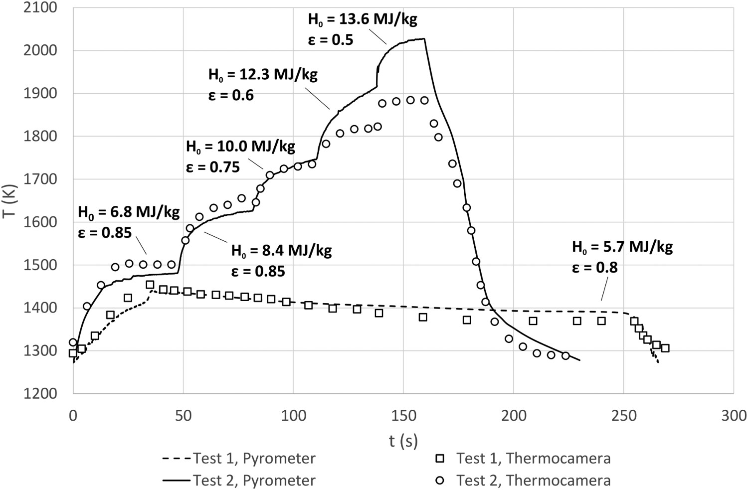
Rocket propulsion
The Aerospace Propulsion Laboratory of University of Naples ‘Federico II’ is located inside the military airport in Grazzanise (CE), near Naples, and it is only accessible with authorisation by the Italian Air Force. It was set up primarily for the purpose of testing hybrid rocket engines. Being equipped with a test bench and a general purpose acquisition system, it is extremely versatile as it is possible to easily adjust the experimental apparatus to several classes of tests, including evaluation of performances of propellants and combustion processes, testing of sub-components and/or complete power systems, nozzles [24], catalytic systems, burners, ignition and cooling systems.
Different oxidisers (e.g. oxygen or nitrous oxide) can be stored in tanks and supplied to the motor with a feed line regulated electronically with a controlled pressure valve. Nitrogen is purged into the chamber for burn out or in case of unexpected phenomena.
The lab-scale rocket has an axisymmetric combustion chamber, with 350-mm length and 70-mm inner case diameter. Upstream and downstream of the solid grain a dump plenum and an aft-mixing chamber are set up, respectively. Graphite converging–diverging nozzles with around 10 mm throat diameter are usually employed, but it can be easily replaced by segmented nozzles with UHTC (or other materials) throat insert or by complete ceramic nozzles.
Gas mass flow rates, combustion chamber pressures and thrust can be measured during the test.
In the frame of the current activities on aerospace civil applications of UHTCMC for propulsion, an incremental approach has been employed to design test prototypes of increasing complexity (Figure 5). Ad-hoc test setups are under development. First, free-jet tests will be performed, exposing small button-like samples to the exhaust plume of the rocket. At the same time, flat-disc insert articles will be placed inside the rocket combustion chamber. Finally, the experimental campaign will continue using nozzle throat inserts and sub-scaled complete nozzles characterised by more complex geometry.
Design of the test articles for C3HARME experimental campaign at Hybrid Rocket Propulsion Laboratory and schematic view of test setup with test articles.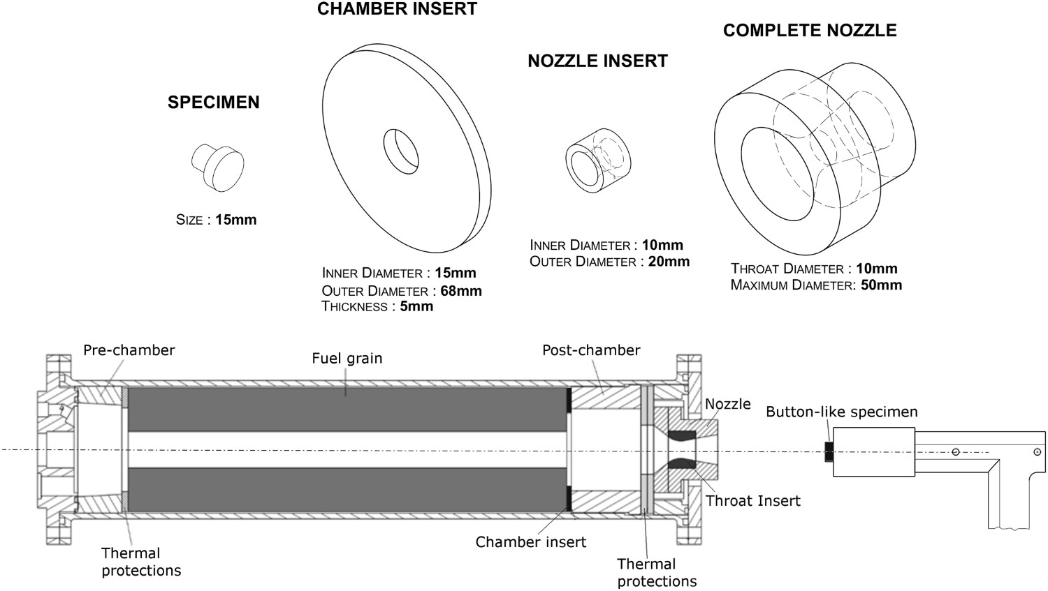
A preliminary configuration test has been carried out, exposing a graphite sample to the exhaust jet of the rocket nozzle. The propellants employed were gaseous oxygen as an oxidiser and a cylindrical grain of solid High-Density PolyEthylene (HDPE) as fuel. Figure 6 shows a picture of this free-jet test, along with the data of the specimen surface temperature, performed by a two-colour pyrometer, and a numerical reconstruction of the temperature vs. time profile, based on the models that will be presented in Section ‘Numerical models and simulations’. It can be seen that the temperature rose to more than 2100 K in less than 5 s, demonstrating the relevance of these tests to heat up materials in a demanding environment.
Preliminary configuration free-jet test at aerospace propulsion laboratory of University of Naples (left) and corresponding profile of specimen temperature, measured and reconstructed by CFD (right).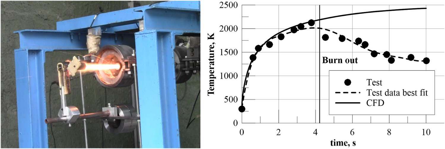
Numerical models and simulations
Parallel to the experimental activities, a great effort is spent to define, validate and employ proper numerical models able to accurately predict not only the thermo-fluid-dynamic flow field in different test facilities and operating conditions, but also the behaviour of the materials prototypes [15,25,26].
Computational tools play indeed an essential role both for the modelling of material structural behaviour [27,28] and as support to design of arc-jet or rocket components lab-scale experiments [29-31]. The flow conditions occurring in high-enthalpy plasma wind tunnels and inside hybrid rocket engines are extremely complex [3235] and not all the critical parameters can be measured experimentally, so the verification of the thermo-fluid-dynamic field must be a combined effort of experimental diagnostics and CFD simulations through interactive processes, providing a step-by-step improved understanding of the facility performance [14,36,37]. Furthermore, numerical research can allow reducing the number of tests needed for experimental characterisation, providing useful results in a relatively short time.
For these reasons, proper numerical models have been defined and are presented in next sub-sections.
Characterisation of arc-jet flow field and thermal analysis
Several models are employed to study aero-thermo-dynamic flow fields inside the arc-jet wind tunnel and the thermal behaviour of the materials.
A one-dimensional chemical-equilibrium model, based on NASA CEA (Chemical Equilibrium with Applications) software [38], simulates the evolution of high-enthalpy molecular gases (e.g. N2, O2) in the facility nozzle, providing the conditions to be set at the inlet of the test chamber for the analysis of the flow field around test articles.
Computational fluid dynamics is also often used to evaluate the flow conditions in the facility. Chemical non-equilibrium models with at least five reacting species (N2, N, O2, O, NO) describe the chemical field, involving dissociation/ionisation reactions. 2-D axisymmetric or 3-D computational domains are used to simulate steady and unsteady flows. Turbulence modelling is taken into account to describe properly the temperature and species distribution.
Finally, thermal analyses of the samples are performed, considering the fluid/material interaction for an accurate analysis.
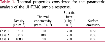
In the following, some computational results obtained with these models will be presented. In the framework of the current research activities, focused on the characterisation of new-class UHTCMC materials, a parametric analysis was performed to study the effect of varying the thermal properties of the samples. For a fast estimation of the conditions at the nozzle exit section, the aforementioned one-dimensional model is employed.
Different simulations have been performed assuming that the total gas mass flow rate was 1 g s−1, with a N2 mass fraction of 0.8 and O2 mass fraction of 0.2. The condition of maximum torch arc power (41 kW) was considered, assuming that the efficiencies of both the torch and the nozzle are 0.7.
At nozzle exit section, a Mach number of about 3 is expected, with temperatures in the order of 2700 K and a considerable amount of dissociated nitrogen and oxygen (both around 0.2 in mass fractions). The conditions calculated by means of the one-dimensional model were used to set the inlet boundary condition for the CFD simulation of the flow field in the test chamber, whose solution showed a static pressure in the order of 10 kPa and a temperature higher than 5000 K in the fluid surrounding the specimen.
Thermal properties considered for the parametric analysis of the UHTCMC sample response.
The simulations were made considering not-catalytic walls of the solid components. Transient simulations were carried out. The initial temperature on all the solid components was set to 300 K. The operating time equal to 60 s was sufficient for the front surface of the samples to reach a steady value of the temperature.
Figure 7 reports the temperature distribution inside the sample at t = 60 s, for the three analysed cases. The scale is the same in the three pictures. The main effect of the low value set for the thermal conductivity in cases 1 and 3 is to keep the rear part of the assembly relatively cooler than the front part, even at the end of the simulation. The higher thermal conductivity set in case 2 causes the heat delivered at the front surface to be conducted throughout the specimen: it follows that the temperature distribution more uniform, whereas the front surface temperature is lower than in the case of a conductivity of 10 W (m−1 K−1.
Temperature contour inside the sample after 60 s, (a) case 1 (low thermal conductivity), (b) case 2 (high thermal conductivity), (c) case 3 (low density).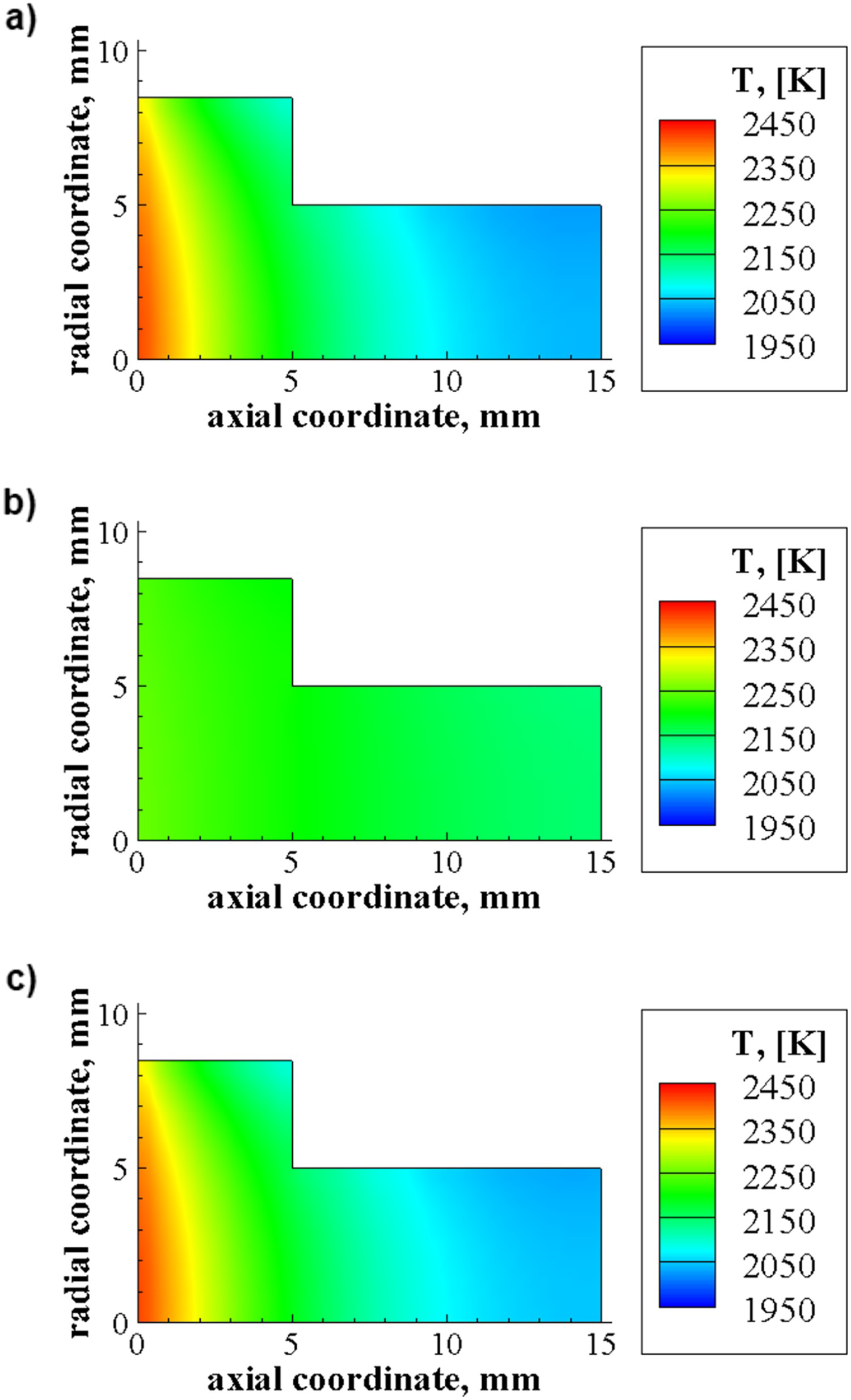
The time histories of the maximum temperature value computed on the sample front surface, for all the simulated cases, are reported in Figure 8. The steady state temperature is around 2400 K for the cases with low thermal conductivity, independently from the density. The curve corresponding to case 2 shows that a higher value of the thermal conductivity leads to a slower rise in temperature and to a lower steady state value (2200–2300 K). On the contrary, a lower density (case 3) leads the temperature to increase more rapidly and does not affect the steady state.
Time histories of the maximum value of sample front surface temperature. The material properties in each case are reported in Table 1.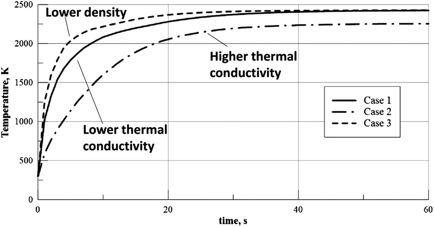
Simulation of hybrid rockets and thermal analysis of discharge nozzles
Proper numerical models developed for the evaluation of operating conditions and thermo-fluid dynamic flow field inside the combustion chamber of hybrid rocket engines have predictive capabilities and provide additional information that are difficult to collect experimentally. In particular, one- and two-dimensional models, validated by comparison with experiments [26,45], are employed not only to reconstruct the conditions inside the combustion chamber, but also to provide the required inlet boundary conditions for the numerical analysis of the flow throughout the rocket discharge nozzles or of the external exhaust plume of the engine (as shown in Figure 6), taking into account a detailed description of chemistry [46].
In the framework of the current research activities, the mentioned models can be employed in order to carry out thermal analysis of simple specimens or more complex components, coupling the resolution of the flow field with the transient thermal heating of the solid components.
Properties of the solid materials.
The simulated engine operating conditions were retrieved from an experimental test case [45]. Gaseous oxygen, at a mass flow rate of 27 g s−1, was injected through a cylindrical-port HDPE grain, and burnt for 11.4 s. The evolution of the flow field through the nozzle (having a length of 35 mm and a nominal throat diameter of 9.6 mm) was simulated, acquiring information about the thermal loads on the solid components. The total heat flux profile computed along the nozzle inner surface, for cold wall (300 K), reaches a maximum value of 18 MW m−2 around the throat section.
Figure 9 displays the temperature distributions in the solid region for the three analysed cases, calculated at the final instant of the burn of the simulated test. In the case of graphite nozzle, due to the relatively higher thermal conductivity, high temperature occurs in the whole solid region, with a difference of around 500 K between the maximum value, reached around the nozzle throat, and the minimum value, reached on the backward external surface. In the case of the UHTCMC throat insert, a more pronounced temperature gradient is expected inside the ceramic insert, whereas the temperature in the converging/diverging graphite sub-section is more uniform. Finally, in the case of complete UHTCMC nozzle, high temperatures are faster reached on the internal surface, whereas the external region remains relatively colder, determining severe temperature gradients for the entire firing duration.
Temperature distribution in the solid nozzle at the end of the test (t = 11.4 s): (a) Complete graphite nozzle, (b) Graphite nozzle with UHTCMC throat insert, (c) Complete UHTCMC nozzle.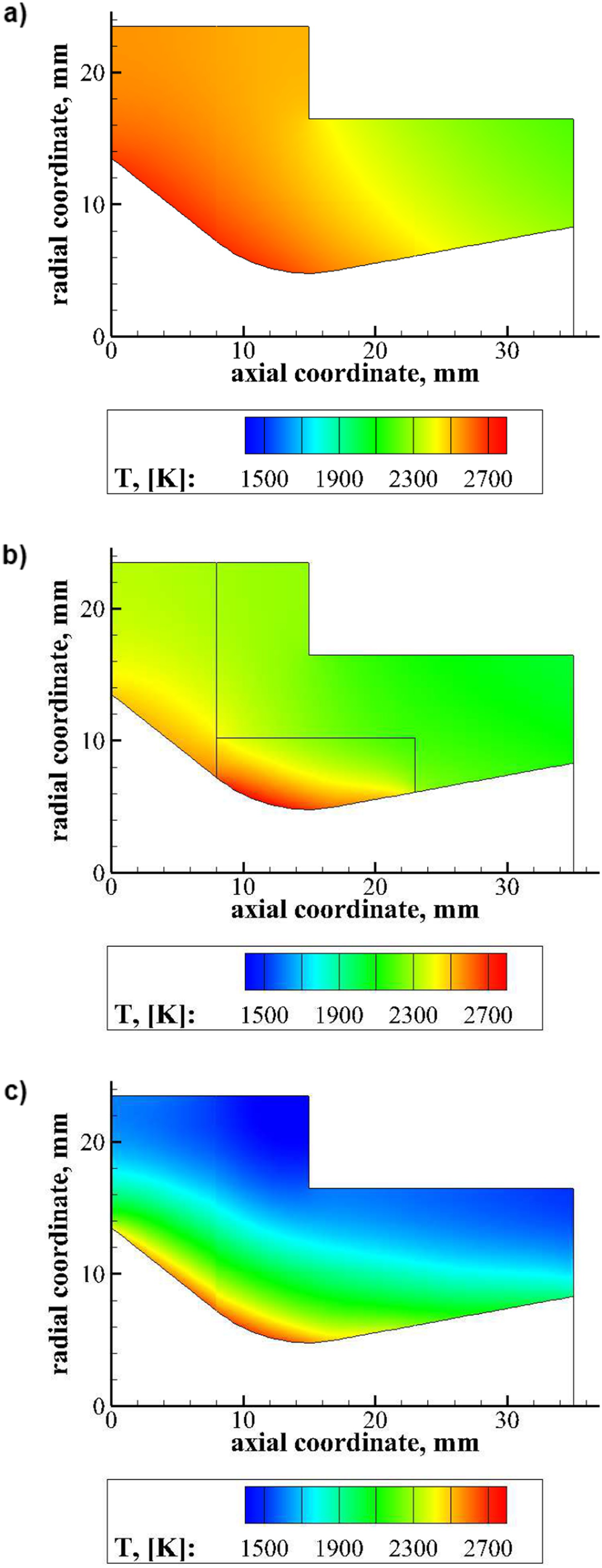
Conclusions
In this work, current experimental and computational activities focused on the characterisation of UHTCMC for space propulsion and hypersonic re-entry applications, carried out at the University of Naples ‘Federico II’ in the framework of the C3HARME project, are presented.
To investigate the materials behaviour in atmospheric re-entry conditions, relevant tests on samples with different shapes and sizes with an arc-jet facility are foreseen, with a maximum flow total enthalpy higher than 20 MJ kg−1, supersonic Mach number in a gas atmosphere with high concentration of atomic oxygen. The results of two preliminary experiments, with increasing enthalpy levels, carried out on a UHTCMC sample have been presented. The specimen surface temperature reached a peak value exceeding 2000 K. The comparison between the measurements of the pyrometer and of the thermocamera allowed the estimation of the spectral surface emissivity, which was decreasing during Test 2, possibly because of the surface oxidation, which was clearly visible also from the whitish coloration of the sample after test.
The Aerospace Propulsion Laboratory, mainly conceived for testing of hybrid rockets, allows also the characterisation of materials under extreme conditions representative of propulsion environment. An extensive experimental campaign is foreseen for testing prototypes of increasing complexity, from small samples exposed to the exhaust plume of the rocket, to complete sub-scaled De Laval nozzles. A preliminary free-jet test has been carried out on a graphite sample, reaching a temperature higher than 2100 K, demonstrating the relevance of this kind of test.
The experimental activities are supported by properly defined CFD models, which allow to predict the complex thermo-fluid-dynamic flow field and operating conditions around the test articles and to analyse the materials behaviour, besides providing information that cannot be directly measured. In the present work, parametric analyses have been performed to study the effects of materials physical properties on the thermal behaviour in both the arc-jet and the hybrid rocket environments.
Footnotes
Acknowledgement
This paper was originally presented at the Ultra-High Temperature Ceramics: Materials for Extreme Environments Applications IV Conference (Windsor, UK) and has subsequently been revised and extended before consideration by Advances in Applied Ceramics.
Disclosure statement
No potential conflict of interest was reported by the authors.