
Abstract
Secure communication involving cluster heads in a sensor network is vital as they are responsible for data aggregation and for taking important decisions in their groups. In this article, we propose a scheme for secure communication via such nodes in a sensor network. In our approach, the base station provides a function to the cluster head of each group, which is used to compute the key for the secure communication with the base station. The protocol is first elucidated for a fixed cluster head in each group and later it is extended for dynamic cluster heads. Each function is computed using a certain number of points on the curve using Lagrange's interpolation [10]. The curve computed from the function intersects the Y axis at a point which is considered as the key of the cluster head. The advantage of this approach in providing secure communication out of a cluster head is that an adversary will not be able to get hold of the function by attacking the cluster head alone. This is because instead of storing the function in the cluster head, sub-functions are generated and distributed among the sensor nodes in each group. After the distribution of the sub-functions, these functions are discarded from each cluster head. When a cluster head wants to communicate with the base station it accumulates sub-functions to compute the function to compute the key used to encrypt/decrypt messages sent and received to and from the base station. For updating the functions, the sub-functions are updated using the information provided by the base station. The key distribution approach requires that the function is to be kept secret all the time. However, since it is present in the cluster head to compute the key, it is difficult to ensure its security. We have experimentally evaluated our scheme through the simulations using TinyOs and TOSSIM and the results show that latency can be improved by using the sub-functions updating approach rather than re-generating the functions and the sub-functions. Also, updating the sub-functions requires reduced computation and bandwidth requirements than updating the sub-keys because updating of the keys needs to be done from scratch whereas updating of the sub-functions are done using an updating parameter.
Keywords
Introduction
Wireless Sensor Networks (WSN) have become an important area of research because of their applications in military, airport security, habitat monitoring, health monitoring, and in robotic toys among others. In some applications like military [2], sensor nodes are deployed in a region randomly using a helicopter. In some other applications like border security, they are deployed manually. A sensor network consists of general-purpose sensor nodes, cluster heads, and relay nodes. All of these nodes are equipped with limited CPU, memory, antenna, and battery power [16]. Each sensor node is capable of processing data and communicating with neighboring nodes. Security [1, 5, 12, 18] is one of the most important issues in WSN. For example, a wireless sensor network uses a Radio Frequency (RF) channel, which is not a secure channel for the communication. It is difficult to prevent an adversary from compromising the security of sensor networks because of untraceable sensor nodes and less physical protection.
Secure communication out of a cluster head is more important in sensor networks because it is responsible for aggregating the data and taking decisions on behalf of a group of nodes and also, for communicating with other cluster heads and with the base station. A notable example demonstrating the need of a cluster head's communication security is as follows. Assume that there is a group of sensors in the region A and another group is in the region B, and each group is managed by a cluster head. Assume that the cluster heads of the region A and B wants to communicate. If both the cluster heads are using private/public key cryptography then they need to have {private, public} key pair for the authentication of data and secure communication. According to this cryptography technique, if the cluster head of the region A wants to send data to the cluster head of the region B then it should encrypt data using the public key of cluster head B. Later, the cluster head of the region B decrypts the data using its own private key. This encryption/decryption method is vulnerable because if an attacker can take control of the cluster head then it can get the private key of the cluster head and then decode the encoded data sent by the other cluster head.
We propose a technique where instead of keeping the function in the cluster head, (Fig. 1) it splits the function into sub-functions and distributes those among the sensor nodes in the hierarchy rooted by the cluster head. Using this function, a curve is computed in the cluster head. This curve then intersects the Y axis at a point, which is considered as the key of the cluster head. This key is used for the secure communication with the base station. In this proposed approach, when a cluster head wants to decode data which is encrypted by another cluster head or the base station then it must accumulate the sub-functions to reconstruct the function and then compute the key. In this scheme, an attacker will not be able to get the key by attacking the cluster head as the key is discarded after the distribution of sub-functions among sensor nodes in that group. All the functions can be split into sub-functions. Note that a key can also be split by the cluster head and distributed as partial keys among the group members since the cluster head can split a key using Lagrange's interpolation [10] and a function. However, the advantages of splitting the function by the cluster head into different sub-functions over splitting the keys is that updating the sub-functions consumes less computation and communication overhead compared to updating the sub-keys because re-generating the keys is done from scratch and updating the keys is done by an updating parameter.

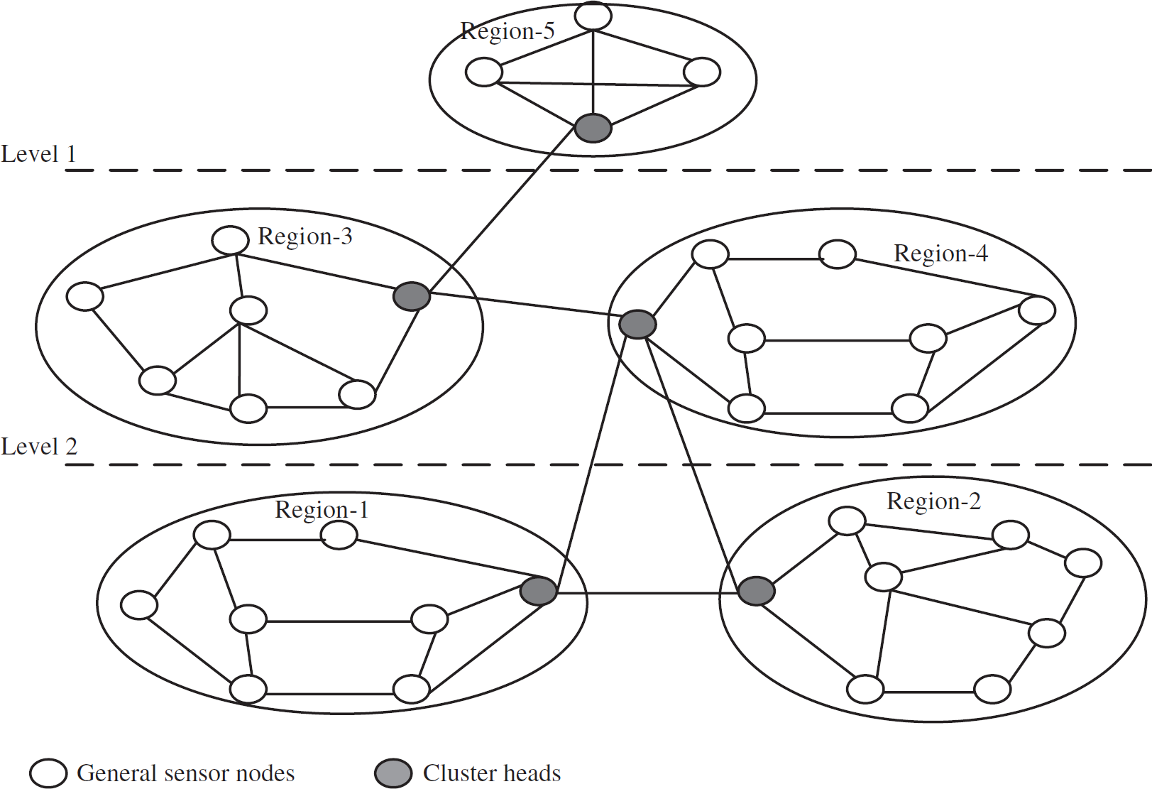
Cluster heads in a sensor network.
In summary, we split the function rather than computing a key in the cluster head and then
splitting it among its group members for the following reasons: Updating of sub-functions has limited computation and communication overhead compared to updating
of sub-keys, because the same updating parameter δ is used by all the sub-functions. The
sub-keys cannot be updated without re-generating a new key in the cluster head and then split it
among its group members. Another way of updating the sub-keys would be using a different δ.
However, for that the cluster head needs to first derive a relation among the sub-keys and then keep
track of the relations among all the δ s. The Lagrange's interpolation does not
provide the relationships among the sub-keys if a key is split by a cluster head instead of a
function. A {Private, Public} key pair needs to be computed [10] in the cluster head if Lagrange's interpolation is
used for splitting the key. First generating {Private, Public} a key pair from scratch, and later
re-computing it from the sub-keys is not energy, computation, and communication efficient in
comparison to computing a key using the sub-functions.
To maintain the freshness of the keys, the sub-functions are updated both in the general-purpose
sensor nodes and in the base station. For doing so, instead of providing new functions to the
cluster heads the base station sends some information to update these sub-functions. Using the
information and the old sub-functions, the sensor nodes can compute new sub-functions which later
can be accumulated by the cluster head to compute the new function to generate a new key. Using this
model, the bandwidth and energy of the network can be saved over re-generating the functions or keys
at every freshness interval. The number of sub-functions needs to compute the function
f1(x) =
at−1xt−1
+
at−2xt−2
+ .… +a1x +
a0 is based on the threshold secret sharing. In this function, the
coefficient a0 is the secret, and the other coefficients are chosen as random variables.
The cluster head chooses n distinct points:
X
j
≠ 0, j = 1…n
and distributes to its n group members. This share is encrypted with a one time symmetric key to
guarantee that the intruder nodes do no get the share of the key and the function. The share of the
key can be written as share
j
(S)
= (Xj,f(X
j
)),
j = 1…n. There is no fixed value for point
X
j
. If we assume Xj =
j, then the shares are denoted as
f(1),…,f(j),…,f(n).
Re-computing the secret key in the cluster head needs t shares of the key out of
n shares. For doing that the secret function is re-computed using Lagrange's
interpolation. If the function is f(x) then the degree of
f(X)<t and
f(j) =
share
j
(s) for
j=1,2,.t. If t general sensor nodes contribute to the
partial key then the function f(X) is of degree t-1 that passes
through all the points. This function f(x) can be computed from the formula
We have experimentally evaluated our scheme through the simulations using TinyOs and TOSSIM [17]. We compared the latency for updating the sub-functions and re-computing the functions. We observed that the latency can be reduced by updating the sub-functions over re-computing the functions from the scratch. We measured the energy consumption for this scheme and compared it with the total available energy in the network. We observed that the proposed approach consumes an insignificant amount of energy when compared to the total available energy. We also compared the bandwidth overhead for different function sizes of the cluster head, which can help to decide the optimum function size. The function size is based on the decryption rate 106decryption/microsecond by the intruder and the time window for updating the key. The chosen functions size in this scheme is 15 bytes based on the experimental results. The key computation method using the functions is explained in Section 5. We also compared the time taken by this protocol for batch updating over individual updating. This helps to compute the time window for updating the function and the key. Finally, we compared the memory usage for different functions sizes. It is important to measure the memory usage overhead, as sensors have small memory capacity [7]. Tinysec packet format shows that changing the packet size can make the communication faster. Memory usage is proportional to the packet size. We also compared the time and bandwidth consumption for updating the sub-functions over the sub-keys. We observe that updating the functions can save the bandwidth in the network.
The rest of this article is organized as follows: Section 2 provides the related work. Section 3 presents the system model. In Section 4, the function computation and distribution is proposed. In Section 5, we study the properties of the function. Section 6 reports the performance evaluation, and Section 7 concludes the article.
This section provides the overview of the work done in the security and the key management area in sensor networks.
Perrig et al. [13] developed a security protocol called SPIN. Two concepts μTESLA and SNEP have been introduced. SNEP provides two-party data authentication, data confidentiality, freshness, and integrity whereas μTESLA takes care of the authentication for broadcasted data. The advantage of SNEP is low communication overhead for semantic security. μTESLA works with delayed disclosure of symmetric keys. The sender chooses a key K n from a key chain and uses a one-way function to compute the other keys. It divides the broadcast time interval and associates each key with an interval. The key is sent from the sender after a certain delay. The receiver knows the schedule for disclosing the key. It uses symmetric key which is computationally efficient than the public-key cryptography. However, over a period of time, an intruder can know the disclosing time of the key from the sender and can compute other keys as each key is associated with other keys. With our proposed protocol at a decryption rate of 106 decryption/μSec [7] the intruders do not get enough time to decipher the key because it is updated frequently.
Eschenauer et al. [6] presented a key management scheme which has selective distribution and revocation of keys in sensor nodes. Their scheme is based on the probabilistic distribution of the key, in which they guarantee that two neighboring nodes will have at least one common key in their key ring. This key is used by the neighboring nodes to encrypt/decrypt messages. Three steps followed in this method are key pre-distribution, shared-key discovery, and path-key establishment. In key pre-distribution phase a large pool of keys (217 − 220) and their key identifiers are generated. Then k keys out of P are chosen to generate a key ring and put in the sensor nodes. In the shared-key discovery phase the sensor nodes find their neighbors who share at least one common key. The nodes broadcast the identifiers of the keys it has within their communication range. The neighboring nodes check to find a common identifier; if they do then they create a secure communication path. The advantage of their scheme is that 75 keys are needed from 10,000 keys in order to have 0.5 probability of sharing a key. However, to have the higher probability, all the nodes need to have a master key. If an attacker can forge the master key then the security of the whole network is compromised. With our proposed approach, the key is discarded by the cluster head after the distribution of sub-functions among sensor nodes in that group and hence cannot be forged.
Zhu et al. [19] developed a key management protocol called LEAP. It uses four types of keys: individual key, group key, cluster key, and pairwise shared key. The individual key is shared with the base station. The base station can perform secure communication with the nodes using this key. The group key is used by the whole group and the base station. It is used for broadcasting messages for a particular group. The cluster key is shared by a node and a node from a different group. It is used to have secure individual communication with the other group's nodes. The pairwise key is shared between immediate neighbors. Each node is uniquely identified in this scheme. Each node has different types of keys to communicate with the neighbor or the cluster head or the node from another group which makes the network secure. However, each sensor node needs to store too many keys which are not possible because of memory constraint. The experiments conducted to establish that our approach of updating the key and sub-functions do not have high bandwidth overhead and memory usage. In addition, updating of the key is done by an updating parameter so that the re-computation of the key is not done from scratch.
Matt et al. in NAI LAB report [2] explored different security and key management protocols. They have developed Identity-Based Symmetric Keying and the Rich Uncle protocol. First, they have analyzed existing network security protocols. Then, they developed the keying protocol suitable for distributed sensor networks. Their main goal was to overcome the battlefield energy constraints.
Du et al. [4] modeled a scheme which uses node deployment knowledge to provide key management in sensor networks. It is assumed that sensor nodes are deployed in groups. If N is the number of deployed sensor nodes they can be divided into t × n groups. They specify an index (i, j) and points (xi, yj) associated with the group G i,j . The neighboring nodes can share a key from a small key chain as the nodes know the probable neighbors at the time of key pre-distribution. However, the simultaneous dropped nodes from a helicopter will become neighbors, is not a valid assumption.
Sun et al. [14] proposed a model for
providing access control in different groups. For providing data to a particular group they form a
distributed network in a tree structure. In this scheme, each sub-tree can have different keys
depending on the application. The users can have a separate private key for inter sub-tree
communication. For building the key graph they follow three steps: Associate leaf with their parents. Associate the upper level parents. Connect all the sub trees.
Rogers et al. [3] proposed a model in which the key discovery is done using privacy homomorphism and the Chinese Remainder Theorem. The pre-distribution of the keys is done before deploying the network. Instead of sending the index associated with the key to find the neighbor who is sharing at least one key from the key chain, the modified Rivest's scheme (MRS) is used and the keys are sent in an encrypted format. The path discovery for secure communication is done without knowing the actual keys. However, it needs to do too much processing before the key discovery which is not practical in sensor networks.
Karlof et al. [7] proposed and implemented a sensor network security protocol called TinySec. The packets used for TinySec are up to 32 bytes in size, and removing some bytes from the packet can make the security packets more accommodating which can keep the bandwidth overhead low. The authors provide performance, security, and memory requirement of SKIPJACK algorithm. SKIPJACK is a cipher-block chaining algorithm implement in TinySec.
Sensor Network Model
This section describes the system model of a sensor network considered for the cluster head security protocol. We consider a network composed of sensor nodes which do not have tamper resistant hardware. The deployment of the nodes is dense so that multiple sensor nodes can sense a similar event in a particular region. The sensors collect data in each group and forward to the cluster heads. The cluster heads communicate with the base station and with other cluster heads of different groups. Each cluster head has a pre-deployed key which is used for secure communication with the other cluster head in another group. This key is common among cluster heads. Instead of keeping the main function which computes the cluster head key, it is parted using Langrage's interpolation and distributed among the group members. Since the cluster head is the one which can only communicate with the other groups, it needs to accumulate its sub-functions to compute the key. When one cluster head is sending a message to another cluster head, it will encrypt the message using its own key, and since the other cluster head will re-compute the key using the same method it can decrypt the message.
Figure 2 shows the system model of a sensor network organized in a hierarchical structure. In this figure, 5 groups are shown. Each group or region consists of general sensor nodes and a cluster head. The groups are organized in physical levels. These levels can have no-read-up and no-write-up policies, which are used in the military system [2] for data access. The cluster head of a group is authorized to communicate with other cluster heads. The choice of communication among the cluster heads is based on the application. For example, the cluster head of region-5 has the highest level of access so it can collect information from all other regions in Fig. 2.
A hierarchical architecture of a sensor network.
The architecture in Fig. 2 can be used for a border security application to monitor people or vehicle entering into the country without authorization, or to monitor the activities of drug traffickers across borders, etc. One can deploy sensor networks across the border in clusters or groups as in Fig. 3. We can place the base station in a physically protected area to manage the sensor nodes and collect data reported by them. The base station can send queries or commands to other sensor nodes. Also, the general sensor nodes send sensed data periodically.

Border security application using sensor network.
Before presenting the cluster head security protocol in details, here are some assumptions
related to the sensor network architecture considered in this article. The network is physically deployed and is organized in different groups or clusters using some of
the existing techniques [1, 5, 12, 18]. Each group G includes N nodes and one cluster head.
Only the cluster head communicates with the base station. All the messages are broadcasted, and the
links among nodes are bidirectional. The base station is DC powered and is fault tolerant. Each
cluster has a unique cluster identification and each node knows its cluster id and its own unique
identification in that cluster. The nodes know their one hop neighbors. The base station is capable of authenticating all
broadcasted messages. If a node is compromised, all its information will be compromised. However,
the base station is physically secure and considered safe. Since wireless sensor networks use broadcast-based communication, we assume that an adversary can
eavesdrop on all traffic to intercept messages. It can inject false data into the network. It can
alter transmitted data, and replay the old data. It can also do resource consumption attack by
sending false data or readings to other sensors. Resource consumption attack can drain the
nodes' batteries and waste the network bandwidth. This article does not address the threat,
where an adversary steals a node, changes the security features, and puts it back in the network to
pretend it to be an authentic node. For rectifying this problem, the updating of the sub-functions
should be fast enough so that the adversary should not be able to compute the function and the key
before it expires.
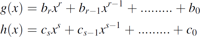
Functional Decomposition of Polynomials
This section provides the technique for functional decomposition of a polynomial used in our
model. Let us assume that there exists a function, f(x) =
x4 − 10x2 + 1 such that
f(x) =
g(h(x)), where the function
f(x) can be decomposed into
g(h(x)). For example, the above function can be
decomposed into following: g(x) =
x2 − 10x + 1 and
h(x) = x2. One of the
properties of functional decomposition is that at the time of decomposition new polynomials can be
inserted into the function. The function f(x) =
x4 − 10x2 + 1 can be
decomposed as follows: x4 − 10x2
+ 1 = (x2 − 10x +
1).(x2) Polynomials can be inserted to the linear components of the
function as follows:

It can be further decomposed into the following functions:

The other important property of functional decomposition is that it can interchange the equations
for the functions g(x) and h(x).
For example, if we want to decompose x5 then we can have
x2.x3. x5
= x2.x3 =
x3.x2. Let us say initially we choose
f(x) = x2 and
g(x) = x3. The functional
decomposition property still holds if we make the equations f(x)
= x3 and g(x) =
x2. The generalized form of the function is:
Algorithm for Polynomial Decomposition
If we consider a function f(x) which has a base field
K then the steps for the functional decomposition would be as follows: Initialization, Factorization, Finding candidates Determining left components at the process of decomposition Looping through the process.
Step 1: Initialization
In this step, the functions f(x),
g(x) and h(x) are initialized
with the polynomials. Let the compliment of g0 is

Step 2: Factorization
Factorize
f1(Y)f2(Z)
−
f1(z)f2(Y)
into irreducible components where
f1(Y)f2(Z)
and
f1(z)f2(Y)
are bivariate polynomials. The near separated polynomial of
a0(Y, Z) is as follows:

Step 3: Find the candidates
To find the candidates, we have to follow the rule where the product of
a
j
(Y, Z) with the smallest degree
should be both multiple of
Step 4: Determining left components
Compute g
i
(X) such that
Step 5: Loop
In order to compute the functional decomposition of multiple components we need to follow the
loop. The loop works as follows:

Spanning the Network for Sub-Function Distribution
In this section, we explain the spanning of the network for sub-function distribution. If the cluster head cannot find a direct link with all other nodes in its group then it spans the nodes which are one hop away and those neighboring nodes visit their neighbors. The following notations are used to explain the proposed algorithmic steps.

Each node in the network is spanned to make sure they are part of the network. The cluster heads or the base station can execute this algorithm to visit each node. If this algorithm is executed by the cluster head then the nodes of a particular group are visited. If the base station runs this algorithm then the all the nodes in that region are reached. This algorithm is similar to depth first search. Using this algorithm we can create a link list in the second step which helps us to provide multi-level access.
Step1: Spanning the network N
For each sensor node S in G[N]
do visit S in G[N]
while (not visited G[N])
for each sensor S in G[N]
do if G[N] is Not visited
then visit (G[N])
Function Computation and Distribution
In this section, we first present the basic idea of the scheme and then provide the details of the protocol.
Overview of the Scheme
Before deployment of the network each node is pre-loaded with a symmetric key
S
k
. Each group of nodes has a different key, and the
base station BS has the knowledge about all the keys. For example, groups 1, 2, and
3 can have keys SK1,
SK2, and
SK3. If the BS is responsible for
communicating with n different groups then it maintains a set of symmetric keys
{Sk1, Sk2,
Sk3…………S
kn
}.
After deployment of the network, each group is organized using the self-organization process [8] and one of the nodes in each group is chosen
as the cluster head. The cluster head is responsible for the following tasks: It needs to keep track of all the nodes in its group and accommodate the newly joined node. In
this article, we do not handle the group membership events like join, merge, leave, and partition
and we do not propose any self-organization method either. Methods such as [2, 14] can be used here. It does the data aggregation [7, 11] on behalf of its group and sends the data
to the base station. The data is sent in encrypted form. The base station can decrypt the data using
a common key derived from a function. We discuss about this function in more details afterwards.
After the self-organization process the cluster head CH communicates with the base station BS and gets a function f(x) which is used for cluster head security. This f(x) is used to compute the key. In order to guarantee that any node cannot get the key by attacking the cluster head, the function in the cluster head is divided into different sub-functions. For example, the function f1(x) of CH1 can be subdivided into f1(x) = f11(x) +f12(x) +……….+f1n(x). The cluster head distributes the sub-function among its group members and notifies the BS so that it has the knowledge about each group. Thus, instead of providing each CH with a new function, BS can update the sub-functions using certain information like the points to create new sub-functions from previous sub-functions. We discuss about the update process later in this section. The CH destroys the f(x) after the distribution of sub-functions so that an attacker cannot get it. As the f(x) is used to compute the key in CH, the cluster head needs to gather the sub-functions to compute the key K f . This K f is used for secure communication with the BS.

Detailed Description of the Scheme
The following steps are followed in order to propose the scheme.
Computing the function in the base station and its distribution to the cluster heads
The base station BS computes the function f(x)
for each cluster head CH. The function is different for each cluster head. For
example, the cluster heads CH1, CH2, CH3 have the
functions f1(x),
f2(x), and f3(x)
respectively. The function is of the form:
A one time symmetric key S
k
is used to
encrypt/decrypt the messages before computing the key
K
CH
using f(x). A
MAC is also computed to authenticate the source of the messages
Msg
s
. In Fig. 4 the message exchanges are as follows: 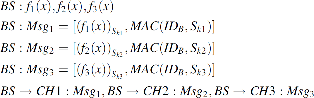
Computing and distributing the functions.
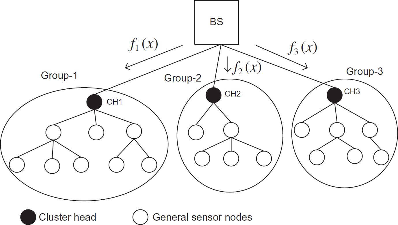
After receiving the function f(x) from the BS
the CH divides the function and distributes it among the general sensor nodes. In
Fig. 5, the function is divided as follows.
The CH1 can split the function
f1(x) into 8 sub-functions: 
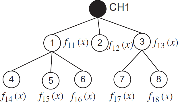
Splitting and distributing the sub-functions.
The function can be written as
Likewise the CH2 and CH3 divide the functions
f2(x) and
f3(x) as follows: 
After distributing the sub-functions, the cluster heads reports to the base station about who has
what sub-function. 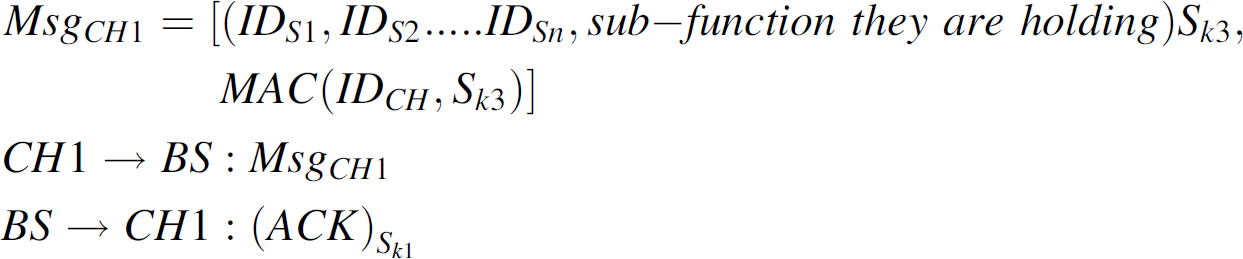
When the cluster head wants to communicate with the base station then it gathers the
sub-functions from the general sensor nodes and computes the function
f(x). For example the function in cluster head
CH1 can be
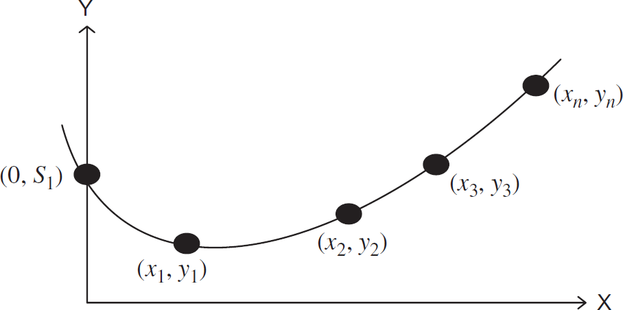
Computing the key from the curve.
The sub-functions are updated to maintain the freshness of the key which can avoid an intruder
from doing exhaustive key search. As a reminder, the functions in the cluster heads are destroyed
after creating sub-functions and distributed among the general nodes in the group. The following
steps show the updating of sub-functions. 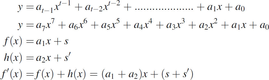
Lagrange's interpolation is used in the BS to compute the functions.
Lagrange polynomials are the interpolating polynomials that equal zero at all given points. For
given points x1, x2, …,
x
N
, the Lagrange's polynomial
P
k
(x) would be: 
According to the theorem
P
k
(x
k
)
= 1 and
P
k
(x
j
)
= 0, for different j and k. In this the
polynomials interpolate through the points (x
1
,
y
1
), (x
2
,
y
2
), …,
(x
n
, y
N
).
It could be written as P(x). 
As BS has the knowledge about the points, functions, and the process, it can update the sub-functions using point information. BS also updates the curve in order to compute the new keys which will be used for encryption/decryption. Figure 7 shows a simple example of a straight line where the points can be updated keeping the same function.
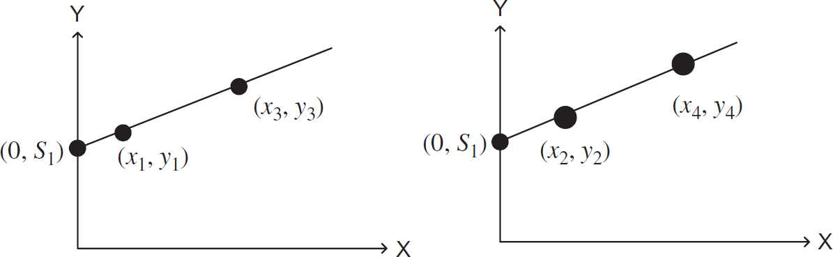
Different points of the same function.
If an attacker injects a false sub-function then the computed function in the CH
would be different, and so is the key. Though the cluster head is not compromised, the keys
K
CH
in the BS will not match. To find
the sub-functions which are not authentic, the CH sends the curve
C along with the encrypted message to the BS using the key
K
CH
. 
If the key matches with the BS then the base station sends ACK to confirm that the key and messages are verified. If the key does not match then it finds out the false point from the curve as it can compute the original curve.
Figure 8 shows the updated points and
the new key

Updating the sub-functions using points.
Here, we define some properties related to merging and updating keys.
Property 1
If (x, y) is a point on the function
Proof
Consider the number of nodes N1 ∊
G1, N2 ∊
G2,……,N
n
∊ G
n
where G is the group.
(N1∪N2) ∊
(G1∪G2),
(N1∪N2……∪N
n
)
∊
(G1∪G2…….∪G
n
).
∃KCH1s.t
{KCH1 used as cluster head key by
G1}, ∃KCH2
{KCH2 used as cluster head key by
G2}. By merge operation
Property 2
Let R be a point on f(x), and let
{P1, …, Pk} be independent points in
f(x). If R ∊ {P1, …,
Pk} then the updated key
Proof
Assume updating time interval of key
Extension of the Scheme for Dynamic Cluster Head
This section describes the extension of this scheme for a dynamic cluster head. First, we propose an algorithm for choosing the cluster head. Here we introduce some sensors designated as covering sensors. The covering sensors are chosen based on the maximum number of communication links with the neighbors. The cluster heads communicate with the base station and with other cluster heads. The algorithm for choosing covering sensors and cluster head is explained in this section.
Figure 9 shows the modified system model organized in a hierarchical structure consisting of five groups. Each group or region consists of many general sensor nodes, some covering sensors and a cluster head organized into logical levels. For example, the covering sensors of Region-1 are A, E, F, and G. Only the cluster head communicates with the base station after the initialization phase whereas in the initialization phase all the sensors communicate with the base station, so that it is aware of the authenticity of the nodes. The role of the cluster head rotates among the CS in a cluster. All the messages are broadcasted and the links among the nodes are bidirectional. Each cluster has a unique cluster identification and each node knows its cluster identification and its own unique identification in that cluster.

A hierarchical architecture.
The schemes for electing covering sensors and the cluster head in each group are explained here:
The reasons for proposing this clustering scheme are as follows: The energy consumption of a group can be reduced by altering nodes for the role of a cluster
head. Most of the nodes will get a chance to become a covering sensor or a cluster head which can make
it difficult for an intruder to predict who will be the next cluster head. As a reminder, after the
initialization process only the cluster head communicates with the base station. The communication links of the nodes can change with the failure of nodes, so it is crucial to
find the nodes with maximum number of links because it can reduce bandwidth overhead by minimizing
the number of hops for routing packets.
For choosing the Covering Sensors (CS), this protocol finds the links of the sensor nodes with other sensors in that region. We assume that there are S sensors in the region R. The link between the two nodes is denoted as L. Consider an instance of a region R as R1 = (S, L), where S are the nodes in the region R1. For example, in Fig. 10, the sensor node A in the region S can be denoted as S A and the link between nodes A and B is L AB . It uses the following algorithm to get a subset of nodes S′ ⊆ S which covers all the links.

Electing covering sensors and cluster head.
CS ← {} L′ ← L of R
1
While {L′<>empty) do Let (L
A
,
L
B
) be the arbitrary link of L′ CS ← CS ∪ node with the link
(L
A
,
L
B
) Remove from L′ every link incident on either
L
A
or
L
B
Return CS
In Fig. 10, the cluster heads (CS) are A, E, F, and G. After choosing CS, the protocol selects one of the CS as the cluster head (CH). For choosing the CH, an election algorithm is followed; the CS communicate among them to know the energy left and the CS with the highest energy is chosen as the CH. For transmission or reception of messages each node spends energy. Some of the CSs are multi-hop away from others; in that case the spent energy also depends on the number of hops required for communication. In the proposed algorithm, the identification of each CS is denoted as ID CSi . For example, in Fig. 10 the value of i is 4. If in each node the transmission, reception, and the total energy is E Tx , E Rx , E total , respectively, and the number of hops is h and the energy left at each node is E left , then the algorithm is as follows:
n ← number of CS for i ← 1 to n do While (E
left
of
ID
CSi
0) E
left
=
E
total
-
(E
Tx
+ E
Rx
) × h if ((E
left
of
IDCSi+1
>(E
left
of
ID
CSi
)) CH ← IDCSi+1 else CH ← ID
CSi
Return CH
The CS nodes collaborate with each other to find out who is left with the maximum energy. The highest energy sensor among CS is then selected as the cluster head (CH). To balance the energy in the network, the cluster head is rotated after a certain period of time. In LEACH [9], it has been shown that sensors can save energy by communicating in hops instead of directly communicating with the base station. In our scheme, the responsibility of the cluster head is rotated among the sensor nodes to balance the energy as the cluster head consumes more energy than the other nodes.
This part describes the extension of the cluster head security protocol for dynamic cluster head.
The steps for computing the function in the base station and distributing to the cluster head
remains same. This step is explained in Section 5. The new cluster head communicates with the BS after its
selection. The old cluster head also sends a message to the base station to reconfirm the new
cluster head. The message exchanges are as shown below. The cluster key is handed over to the new
cluster head. This key is encrypted using the new symmetric key
S
k
New. A MAC is also
computed to authenticate the source of the messages. 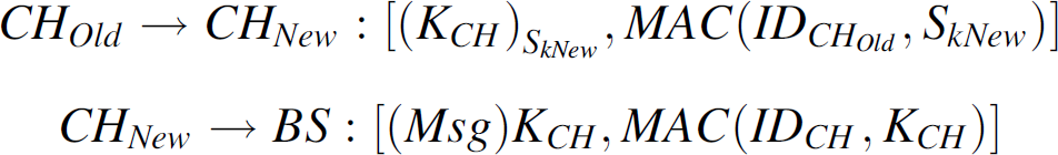
After the new cluster head is selected, the base station uses the same messages for distributing
the function which is explained in Section
5. If the base station computes a new function, then the new cluster head uses the same steps
for this protocol. Sub-dividing the function in the cluster head and distributing among the nodes. Computing the key in the cluster head. Updating the sub-functions. Verifying the key in the base station.
The details of these steps are described in Section 5. If the base station decides to keep the old function because it can save processing and communication energy, then all the nodes that hold the sub-function are notified by the new as well as old cluster head.
Performance Evaluation
In this section, we provide the performance evaluation of this cluster head security protocol. We implement this scheme to observe the latency improvement of updating the sub-functions over re-computing the functions in each group. We use TinyOS and TOSSIM [17] for simulation with 2000 sensor nodes distributed uniformly in a region of 1000 × 800m2. The communication range of the nodes is 40m. The nodes are divided into groups (clusters) of 10 to 50 nodes. The nodes communicate with each other using multi hop paths. We do not simulate the organization of the network and assume that the network is organized as explained in Section 3. The base station broadcasts a function for each cluster head of each group. The cluster head split the function into sub-functions and distribute them among the general sensor nodes. The cluster head reports to the base station about which node holds which sub-functions. After that, the cluster head discards the function to avoid attacks. If some nodes are physically captured by intruders and the application layer software is modified to communicate with the unauthentic nodes, and then they can pretend to be authentic nodes. For rectifying this problem, the updating of the sub-functions should be fast enough so that intruders should not be able to compute the function and the key before it expires.
Energy Consumption
We measure the energy consumption by each group for implementing the cluster head security scheme. The following energy usage parameters [17] are considered for calculating the energy in both Figs. 11 and 12.

Energy consumption for the scheme.

Bandwidth overhead for function and key updating.

Figure 11 compares the energy
consumption for initial process and the total available energy in each group. The energy calculation
in Fig. 11 consists of the following
steps: The message transmission from the cluster head to the base station for the initialization and
reception of function from the base station. Splitting the function to sub-functions and distribute among the group members. Message sent to the base station to inform about the holding party of the sub-functions.
It is assumed that each sensor node has 2, 1.5volts AA batteries. We observe that, the battery power consumption for performing this scheme is very little compared to the total available energy. Figure 12 gives the comparison between the total energy consumed for updating the sub-functions and the available energy in each group. As a reminder, updating of the sub-functions is done using point information from the base station. We observe that this process consumes an insignificant amount of energy compared to the available energy in each group of nodes.
It is important to observe the latency and analyze the time window (approximately 10 h) to prevent intruders from decrypting the keys. To measure this latency we performed an experiment. In this experiment the cluster head distributes the sub-functions among general sensor nodes; later these sub-functions are accumulated to compute the function and the key. As a reminder, the function is computed by the base station and sent to the cluster head. Figure 13 compares the latency of groups for updating the sub-functions over re-generating the functions and the sub-functions. Each group consists of 10 to 50 nodes. The size of the key computed from the function in this experiment is 60 bits. From this experiment we observe that, latency in this scheme can be improved by about 40%. We also observe that, it is not possible by an intruder to decode the key within this time window of approximately 10 hours using exhaustive key search at a decryption rate of 106 decryption/μSec [7]. The intruders do not get enough time to decipher the key because it is updated frequently. The updating time is proportional to the size of the group.
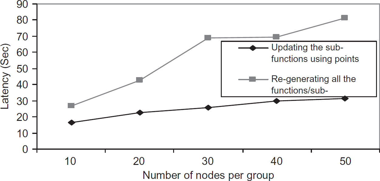
Comparison of latency between re-generating function and sub-function updating.
Bandwidth overhead. The bandwidth overhead is calculated based on the total number of packets over the number of packets per block. We performed an experiment where the function sizes and distributed functions are varied to measure the bandwidth consumption for the key computation. The goal of this experiment was to observe the change of bandwidth overhead with varying function size. The varying function sizes are 8 bytes, 12 bytes, and 15 bytes. The packet size in Tinyos can be up to 32 byte. It is necessary to keep the packet size as low as possible. From Fig. 14 we observe that the change of function size does not change the noticeable bandwidth overhead as long as the function fits into the packet of 32 byte, which makes the decision easier as a 15 byte function can be more secure than 8 byte. The packets used for TinyOS are up to 32 bytes in size, and we learned from the TinySec [7] that removing some of the bytes from the packet can make the security packets accommodating which can keep the bandwidth overhead low.

Bandwidth overhead.
Memory usage. The goal of this experiment is to measure the memory usage for different function sizes. As we discussed earlier, it is necessary to keep the packet size low for saving the communication overhead and memory usage for processing those packets. In order to compare memory usage for splitting the cluster head function, we used the shortest path routing algorithm to deliver the function to its group members. Figure 15 shows the comparison of memory for the function size of 8, 12, and 15 byte.

Memory usage.
The difference is a result of the fact that the node must store: The split function The function for splitting and re-computing the function, and Packets for updating the sub-functions.
We observe that the memory usage decreases from the function size of 12 to 15 bytes over 8 to 12 bytes, this is because of buffering the message and function which do not change for every time the function is split. We conclude that choosing the 15 bytes function would be optimum as it does not have high bandwidth overhead and memory usage. It is more secure and can fit into 32 bytes packets of the network.
Batch updating vs. individual updating. To observe the difference between the time taken for updating sub-functions individually over batch updating of function, we performed this experiment. The goal is to measure the extra available time window in batch updating. Another goal is to make sure that both the methods of distributing the sub-function from scratch and updating the sub-functions by providing information can be done with the maximum packet size of 32 byte. Updating the functions is explained in Section 5. From this experiment we observe that the updating of sub-functions takes less time over re-splitting the functions. This helps us to measure the time window for updating the function. In this case, our protocol gets extra 7 s to update the function before it can be forged, assuming that the key is decrypted at a rate of 106 decryption/micro-second.
We performed this experiment to evaluate and compare the bandwidth overhead for function and key updating, A 15 bytes key is split and distributed among group nodes using Lagrange's interpolation. The number of sub-keys is varied from 10 to 50. For providing new sub-keys to the group members, a new key is computed in the cluster head and is split again among its group members. Figure 17 compares the bandwidth overhead between the function updating and the key updating. Function computing consumes less bandwidth than the key computing, as all the sub-functions are updated using δ. Figure 18 compares the time taken for updating the sub-functions over updating the key. Time taken for updating the sub-keys is almost 4 times than updating the sub-functions. The reason being, updating the keys and sub-keys needs to be done from scratch whereas updating the sub-functions are done using an updating parameter.
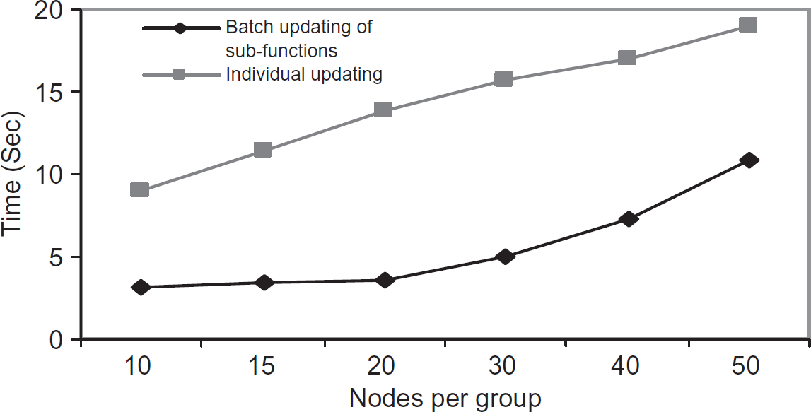
Batch updating vs. individual updating.
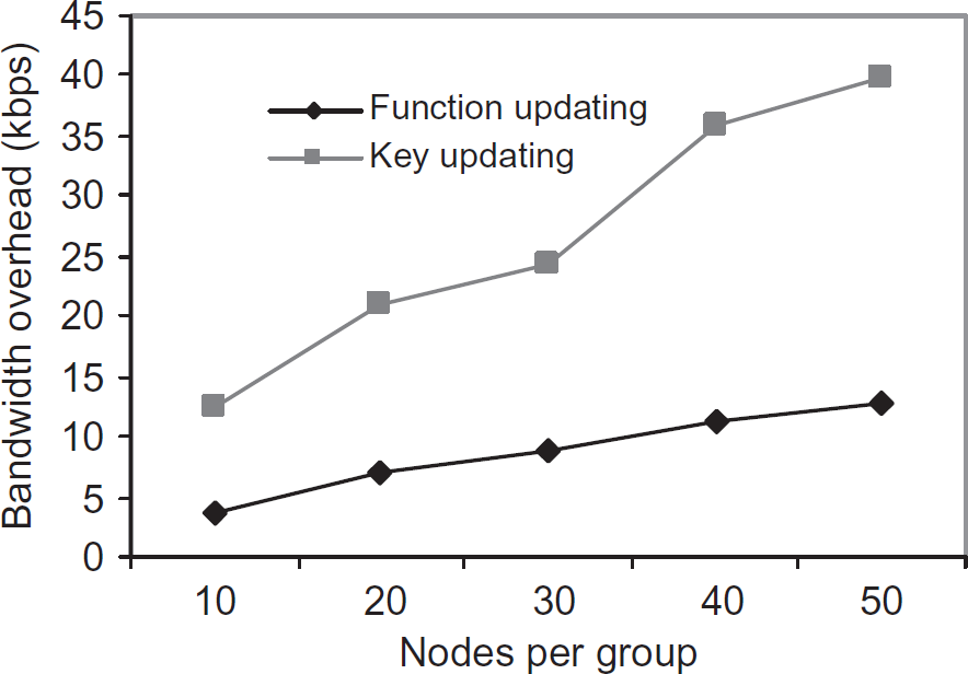
Bandwidth overhead for function and key updating.
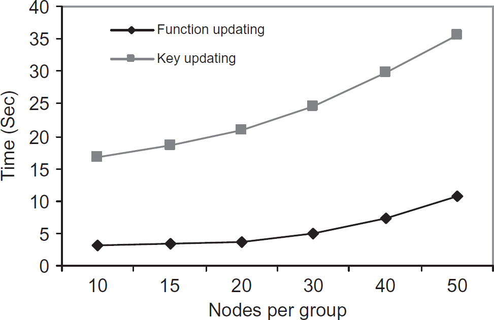
Time for function and key updating.
Figure 19 provides the comparison of
this approach and SPIN for bandwidth overheads. A 15 bytes key computation and broadcast is done in
both the cases. We observe that the bandwidth overhead in SPIN is lesser compared to the proposed
approach. The reasons for that are: SPIN works using the delayed disclosure of keys. The keys are broadcasted from the base station
and none of the keys are modified in the communication path whereas, this approach needs to modify
the keys based on the needs of level and the number of communication messages needed for the key Number of steps needed to setup a communication path is less in SPIN. It has mainly two steps.
First, broadcasting the encrypted messages using the key chain in the base station. The second is
broadcasting the key chain in a predefined time interval. In this approach it has many steps:
choosing a cluster head, setting up the network, distributing the partial key from the cluster head,
and modification of the keys for key updating need.
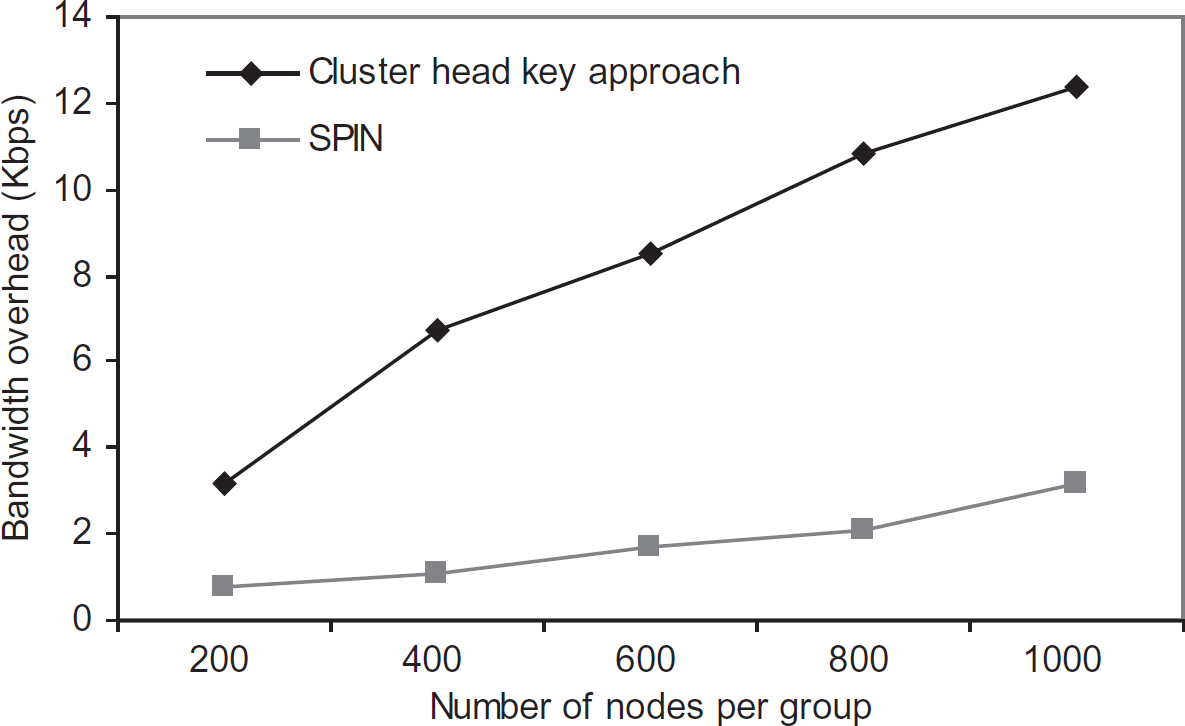
Comparison of bandwidth overhead with SPIN.
In this article, we proposed an approach to secure the cluster heads in sensor networks. This scheme is based on the idea that instead of keeping the function in cluster head it is split into sub-functions and distributed among the general sensor nodes, so that an intruder cannot get the function by attacking just the cluster head. This function can be used to compute the key. The function is computed by the base station and broadcasted for the cluster heads. To maintain the key freshness, instead of re-generating the functions and sub-functions the sub-functions are updated by using point information provided by the base station. The experimental results using TinyOs show the latency of this scheme can be improved over re-generating the functions and sub-functions. It does not have high bandwidth overhead and memory usage. It is more secure and can fit into 32 bytes packets of the network. The intruders do not get enough time to decipher the key because it is updated frequently. Also, in this scheme the battery power consumption for performing this scheme is significantly less compared to the total available energy. A future direction of this research would be deploying the mechanism on real motes and compare the results with the simulation along with considering failures in the sensor networks and proposing fault tolerant key recovery. In that case, instead of using all the sub-functions the cluster head should be able to compute the function using a certain number of sub-functions. For example, if the function of the cluster head is split into 5 sub-functions and distributed among 5 general sensor nodes and 2 of the nodes fail, the cluster head should still be able to compute the function using 3 sub-functions. The key computed key should be the same as before and after failure of the nodes. As part of future work, we will consider implementing a scheme on a real sensor test-bed and will verify our experimental results.