
Abstract
In this paper, a multi-senor information fusion method based on the D-S (Dempster-Shafer) evidence theory is presented for fault diagnosis in an integrated circuit. By measuring the temperature and voltages of circuit components, the fault belief function assignment of two sensors to circuit components is calculated, and the fusion fault belief function assignment is obtained by using the D-S evidence theory. Then the actual fault component is precisely found according to the fusion data. Comparing the diagnosis results based on separate original data with the ones based on D-S theory fusion method, it is shown that the D-S information fusion fault diagnosis method is more accurate. Finally, two fault diagnosis examples of the simple signal magnification circuit and the integrated circuit of industrial case are given.
Introduction
The analog circuit fault diagnosis can be divided into two types. One is called the pre-test simulation method [1] and the other is the post-test simulation method [2]. In these methods, no matter what the pre-test simulation diagnosis or the post-test simulation method, generally, we must analyze the working principle and detailed circuit structure, and know some information about the circuit, and then undergo the diagnosis. However, in many cases, it is very difficult for us to get such information, so the effectiveness of these diagnosis methods is limited; on the other hand, when a fault in an analog circuit occurs, both the fault component's output signal and the neighboring component's corresponding signals will be distorted. If we use only a single signal to diagnose the fault component, it will produce the uncertainty and ambiguity for circuit fault diagnosis. So it is still difficult to find precise fault components by using normal single sensor fault diagnosis methods.
The multi-sensor information fusion involves the integration of multiple and disparate sources of information. The resulting sensor fusion enhances the target performance, and has an accurately classified effect for pattern recognition problems which have uncertainty and overlapping data between two patterns. During recent years, the multi-sensor information fusion technique has received much attention [3 –13], but it is more about applications to multi-sensor target identification systems [14–15], signal processing [16–17], biomedical [18–19], etc. In the domain of integrated circuit fault diagnosis, we have not yet met a similar sensor fusion approach.
In this paper the multi-sensor information fusion technique [20–21] based on the D-S evidence theory is introduced for integrated circuit fault diagnosis. By using the multi-dimension signal processing method of information fusion based on the D-S evidence theory, it reduces the uncertainty of analog electronic components fault diagnosis, and exactly recognizes the fault components. Moreover, it is unnecessary to know the principle and structure of the circuit for the information fusion fault diagnosis method. This is a blind diagnosis method.
This paper is organized as follows. The algorithm of multi-sensor information fusion based on the D-S evidence theory is introduced in section 2, followed by its application to the simple circuit and certain type plane photovoltaic radar electronic components fault diagnosis system in section 3 and section 4 respectively. In order to demonstrate and illustrate the capability of our proposed fault detection approach, the comparison of the diagnosis results by a single sensor is performed. Finally, the conclusions are provided in section 5.
The Fault Diagnosis Algorithm Based on the D-S Evidence Theory
When applying the D-S evidential theory to multi-sensor information fusion, data obtained from sensor is the theory's evidence, and it constitutes the belief function assignment of the object mode needed to be tested, represents a reliable degree of each hypothesis object mode, and each sensor forms an evident group. Multi-sensor information fusion amounts to combining several evident groups to form a new comprehensive evident group. That is to say, we can use the D-S rule to produce comprehensive and precise information for judging object mode.
Figure 1 shows the block diagram of a multi-sensor information fusion system of integrated circuit fault diagnosis. Two sensors measure voltage and temperature respectively. The voltage of each circuit component is obtained by using probes, the temperature of each component is measured by using a thermal image instrument. According to the D-S evidence theory, for each sensor, the possibility of fault to the tested component can be described by a set of fault belief function values. Then two sets of fault belief function values can be put together.

Fault diagnosis based on the D-S information fusion method.
During fault diagnosis, the fault belief function values of the voltage and the temperature are taken as two fault evidence sets, and the fusion fault belief function values will be obtained by the D-S rule. By using the fusion fault belief function values, the fault component can be determined on certain fault determination criteria.
In Fig. 1, m1(A1), m1(A2), …, m1(A n ) are fault belief function values of tested components 1, 2, …, n respectively by sensor 1, m2(A1), m2(A2), …, m2(A n ) are fault belief function values of tested components 1, 2, …, n respectively by sensor 2, m(A1), m(A2), …, m(A n ) are fault belief function values of the tested components 1, 2, …., n respectively by the D-S information fusion method.
The belief function assignment refers to the reliable degree of the hypothesis object mode, and it is personal judgments that are affected by many sorts of factors. A different conception will form different belief function assignment formula. Here we should take the affect of the object mode number into consideration when deciding the belief function assignment.
Definition:


C
j
(A
i
) represents the correlation coefficient of sensor j to object mode A
i
; N
c
represent the object mode number; N represent the total number of sensors, w
j
represents the weight coefficient of sensor j, and its value domain is [0,1]; α
j
represents the maximal correlation coefficient of sensor j; β
j
represent the relevant allocation value of sensor j; R
j
represents the reliable coefficient of sensor j. The m
j
(A
i
) is the belief function of sensor j to object mode A
i
:

The unidentified belief function (uncertain function) of sensor j is:

From formulate (4) and (5) we can see that, except w j which is decided by the sensor's working characteristics and personal experience, and has certain subjectivity, N and Nc are fixed values to specific circuits. The key is how to identify the correlation coefficient C j (A i ) that the sensor j is related to the object mode. The resolution here is to use the fuzzy membership function μ ij to substitute C j (A i ), for these two values which physically represent the same concept, when they are used to estimate the degree that the object mode is subordinate to a certain fault mode, namely their relationship.
Fault membership function is designed by the working characteristics of the sensors and the measured parameters. For a certain component in the electronic system, when the system is working properly, the voltages of the components should be stable and the temperature should have a fixed value relatively. If there are some fault components in the system, generally the voltage and the temperature values will deviate from the normal range. The more deviation there is, the higher possibility of fault there is. For the sake of convenience, the distribution of the fault membership function μ
ij
is defined as shown in Fig. 2, where x0ij is the standard parameter value of the tested component when the electronic circuit is working properly; e
ij
is the normal changing range of the tested component parameters; t
ij
is the maximum deviation of the parameter of the component to be tested; μ
ij
is the fault membership function of the component i tested by the sensor j; x
j
is the real measured value of the sensor j; α is correction coefficient. The formula (6) is the distribution of the fault membership function μ
ij
.
Fault membership function distribution.

The D-S fusion method is best illustrated geometrically: the basic element of the D-S method is a belief function, which can be thought of as a division of a unit line segment into various probability assignments. Probability can be assigned either to individual possibilities (referred to as singletons) or to subsets of possibilities: the set of all singletons are represented by Θ. A probability assignment represents the support accorded to some singleton or subset based on a piece of evidence. In addition, an explicit degree of doubt or ignorance about the evidence can be assigned. The total of all probability assignments equals one: an example of such an assignment over the n subsets of A is shown in Fig. 3. (The “m1” notation can be thought of as the probability “measure” accorded due to the first piece of evidence from “sensor 1”).

The belief function from sensor 1.
The assignment m1(Θ) (uncertain function) represents the degree of doubt regarding the evidence or the assignments, and represents probability not accorded to any singleton or subset. An assignment over the n subsets of B is shown in Fig. 4. The introduction of a second piece of evidence from “sensor 2” results in the creation of a second belief function. With a new assignment of probabilities to a possibly-different set of elements:

The belief function from sensor 2.
Dempster's rule of combination performs an orthogonal combination of these two belief functions. Geometrically, the two line segments are combined to produce a square, which represents the new total probability of combination:
The squares in Fig. 5 represent the probability assigned to intersections of the subsets. The total combined probability of a subset is the sum of all non-contradictory assignments to that subset. Note that Θ combined with any singleton or subset is not contradictory, and so combinations are included in the summations. The actual final probability assigned to each subset is re-normalized by dividing by the total probability assigned to non-contradictory combinations:


The combination of two belief functions from sensors.
In formula (8), C is the summation of all the belief functions multiply, which includes wholly contradictory subsets A i and B j , contradictory subsets means that the two object modes (subsets) cannot exist at the same time, or they are repellent to each other. Here ϕ stands for vacant sets. In formula (7). m(A) represent the probability assigned to intersections of the subsets. The total combined probability of a subset is the sum of all non-contradictory assignments to that subset.
As far as specific integrated circuit fault diagnosis is concerned, A1, A2, …, A k and B 1 , B 2 , …, B k are the same as the subset, which is the sets of all doubted fault components. The m(A) stands for the belief function value that is distributed to each component to be tested after the D-S fusion.
The fault diagnosis algorithm based on the D-S theory can be summarized as follows:
Step 1. the fault belief function values and uncertain function value of each sensor for all kinds of fault patterns are tested, and the fault evidence sets of each sensor are obtained. Step 2. the fusion fault belief function values and fusion uncertain function value are obtained by the D-S rule. Step 3. by using the fusion fault belief function values and fusion uncertain function value, the fault pattern can be determined on certain fault determination criteria.
Correlation Coefficient
Figure 6 shows the principle of the simple circuit to be diagnosed, the circuit is a weak signal magnification circuit. Three amplifiers OP07(A 1 , A 2 , A 3 ) are doubted fault components, U 1 , U 2 , U3 are the key voltages of the component(A1, A2, A3) respectively. The fault form is no supply of electricity power. By using this method, We can set A1, A2, A3 fault respectively.

The principle of the simple circuit.
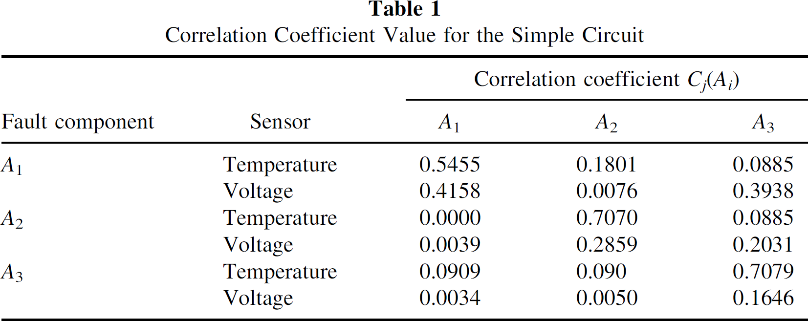
The membership function μ ij in fuzzy sets theory is used to substitute coefficient correlation C j (A i ) in the D-S evidential theory. first, the temperature of each component is measured by a thermal image instrument (inframetrics 600) when the circuit is working properly. Then the new temperature of each component is measured in the fault case, and the temperature fault membership value could be calculated by using the formula (6) given before. In addition, the voltage of each key point could be obtained by probes, and the voltage fault membership values could be obtained as well. By set A1, A2, A3 fault respectively, we can get multi-group membership values data. The detailed data of the membership value are shown in Table 1. For Table 1, in order to solve the problem conveniently and never change the fault character, we suppose e ij = 0, t ij = x0ij, voltage sensor α = 1/2, temperature sensor α = 3.0.
Correlation Coefficient Value for the Simple Circuit
From formula (4) and (5), we can calculate the belief function m
j
(A
i
) and the uncertain function m
j
(Θ). The number of sensor: N = 2, the number of fault components that need to be tested: N
c
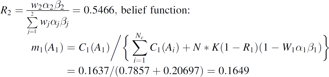
= 3. According to specific experimental data, we select the weight coefficient w1 = w2 = 0.5, adjustment coefficient k = 0.25. From formula (1), (2), (3), for A1 fault, we can calculate that.


We can also calculate other belief function values and the uncertain function values, as is shown in Table 2.
Belief Function Value of Components to be Tested for the Simple Circuit

Belief Function Value of Components to be Tested for the Simple Circuit
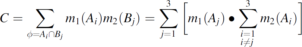
According to the D-S rule, the fusion operation can be realized by formula (7) and (8). In formula (8), C is the addition of all the belief functions which multiply, which includes wholly contradictory hypotheses A1 and B
j
; contradictory hypothesis means that the object modes cannot exist in Θ at the same time, or they are repellent to each other. Here φ stands for vacant sets. In formula (7), A refers to a comprehensive mode of combination object mode A
i
and B
j
, the belief function value m(A) of A is the addition of all the belief function which multiply and that includes hypotheses A
i
and B
j
. Here we mainly mean the combination of A
i
(i = 1,2,3) and the uncertain mode, and thus we can calculate the fusion belief function m(A) as follows:
from (7), we can get the belief function value, which is allocated to A1 (component 1) after fusion, which is:

we can also use the same method to conduct the fusion operation, and get the belief function values that are allocated to other components. Uncertain function value:
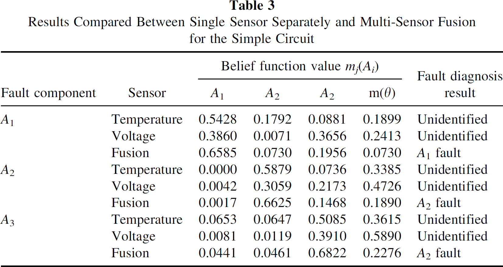
m(Θ) = m1(Θ)m2(θ)/(1 - C) = 0.0729. All fusion belief function is show in table 3.
Results Compared Between Single Sensor Separately and Multi-Sensor Fusion for the Simple Circuit
Results Compared Between Single Sensor Separately and Multi-Sensor Fusion for the Simple Circuit
Fault judgment principles based on the D-S evidential theory generally follows the following rules:
Fault component should have a maximal belief function value and should be more than a certain value; generally, this value should be at least more than 1/N
C
(N
C
stands for the number of components to be tested), and the more the threshold value is the more precise the judgment should be. However, if the threshold value is too large, the belief function value from testing will not meet the requirement. Therefore, we should, according to the situation, choose a moderate value that is more than 1/N
C
. Here the threshold value is 0.60. The difference of the belief function value between the fault component and other components should be more than a certain gate limit value, and here it is 0.30. Uncertain function value should be smaller than a certain gate limit value, and here it is 0.25.
According to the formal fusion algorithm and fault judgment rules, we can get weak signal magnification circuit fusion diagnosis results shown in Table 3. Each component belief function values and uncertain function value to temperature and voltage sensor have been computed. The belief function value after fusion and the uncertain function value are also shown in Table 3. We can see clearly from Table 3 that by comparing the fusion belief function value with the single sensor belief function value the real fault component belief function value is enlarged, while the belief function value of other components is reduced, and at the same time, the uncertain function value is reduced to a large degree. Such as fault component A1, the temperature sensor belief function value m1(A1) = 0.5428, uncertain function value m1(θ) = 0.1899; voltage sensor belief function value m2(A1) = 0.3860, uncertain function value m2(θ) = 0.2413. But fusion belief function value m(A1) = 0.6585, fusion uncertain function value m(θ) = 0.0730. Thus, it greatly reduces the unidentified degree of fault diagnosis. When the fault components cannot be found by two kinds of sensors separately, we can precisely recognize the fault component after fusion. That is to say, the multi-sensor data fusion based on D-S evident theory enhanced the analyzability of the equipments, effectively raised the fault mode recognition ability, and raised the fault components, orientation precision rate.
The Fault Diagnosis of the Plane Photovoltaic Radar Electronic Components
In photovoltaic radar electronic components the fault diagnosis system of a certain type plane [22], we use the fault tree analytical method to search the fault component. By testing the voltage signal of the component on a specific circuit board and comparing it with the normal signal, we can partly judge the fault components. Although this method is simple and convenient, its diagnostic precise rate is poor. We analyze the problem and find that the reason lies in two aspects: On one hand, when some components were broken down in the circuit, their output signals are distorted, and other components connected with them have also been affected, thus their correlate signals have all been affected. That is to say, the former components and the latter components in the circuit affect each other, if we directly use the voltage of the components to diagnose the fault component, it is difficult to decide whether there is fault or not; on the other hand, we do not know the inner structure of the photovoltaic radar electronic equipment, so the fault tree constructed is not well rationalized. For this, we introduce information fusion technology to diagnose the fault components. We use two kinds of sensors to test the electronic circuit components from different aspects, then carry on the D-S information fusion, and judge the fault components. This method is not dependent on the principle andstructure of the electronic components, and is a blind diagnosis method of fault component hunting.
The “voltage-code changed” circuit board is one of photovoltaic radar electronic equipment, and its main function is to change the analog voltage into an eleven-bit digital signal by gradually using the comparing principle. In Fig. 7, in the “voltage-code changed” circuit, there are eight integrated components which need to be tested, they are A1, A2, A3, A4, A5, A6, A7, A8 respectively. Here we already know that the fault component is A1 of the “voltage-code changed” board. In fault diagnosis, we first use the thermal image instrument (instamatics 600) to test the standard temperature of each component that needs to be tested when the circuit board works normally. When some components are faulty, generally speaking, their temperature will be changed (no matter increase or decrease), then we can test the temperature of each component, and calculate the correlation coefficient, according to the above-mentioned fuzzy membership function formula, and we can get the belief function assignment. Additionally, we can also use a probe to test each key point voltage of the component tested, and calculate the belief function assignment of the voltage parameter in connection with each of the components, then use the D-S rule to fuse data, and find the fault components.

The “voltage-code changed” circuit board.
Using the membership function μ ij in fuzzy sets theory to substitute coefficient correlation C j (A i ) in D-S evidential theory, the membership function is defined by the working characteristics of the sensor itself and by the character of the parameter being tested. To a certain component of the electronic equipment, we can define the assignment of the membership function μ ij by formula (6).
In order to solve the problem conveniently, we suppose e ij = 0, t ij = x0ij, voltage sensor α = 1/3, temperature sensor α = 2.8, and Table 4 shows the correlation value of the components that need to be tested on the “voltage-code changed” circuit board.
Correlation Coefficient Value for “Voltage-Code Changed#x201D;

Correlation Coefficient Value for “Voltage-Code Changed#x201D;
From formula (4) and (5), we can calculate the belief function m
j
(A
i
) and the uncertain function value m
j
(θ). The number of sensor: N = 2, the number of fault components that need to be tested: N
C
= 8. According to specific experimental data, we select the weight coefficient w1 = w2 = 0.5, the adjustment coefficient k = 0.2. From formula (1), (2), (3), we can calculate that.

We can also calculate other belief function values and the uncertain function values, as is shown in Table 5.
Belief Function Value of Components to be Tested for “Voltage-Code Changed”

Belief Function Value of Components to be Tested for “Voltage-Code Changed”
According to the D-S rule, the fusion operation can be formula (7) and (8):

from (7), we can get the belief function value, which is allocated to A1 (component 1) after fusion, which is:

We can also use the same method to conduct fusion operation, and get the belief function values that are allocated to other components. Uncertain function value:
m(θ) = m1(θ)m2(θ)/(1 - C). All fusion belief function is show in Table 6.
Results Comparing Between Single Sensor Separately and Multi-Sensor Fusion for “Voltage-Code Changed”
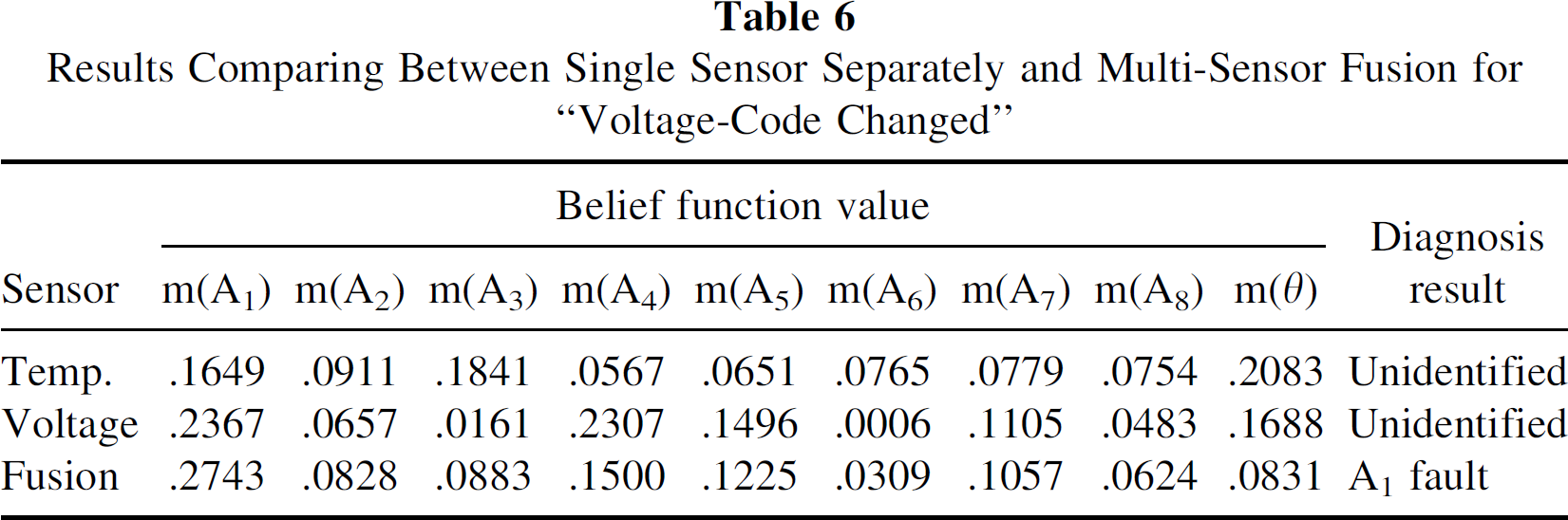
Results Comparing Between Single Sensor Separately and Multi-Sensor Fusion for “Voltage-Code Changed”
Fault judgment principles based on D-S evidential theory generally follows the following rules:
The fault component should have a maximal belief function value and should be more than a certain value; here the threshold value is 0.27. The difference of the belief function value between fault components and the other components should be more than a certain gate limit value, and here it is 0.12. The uncertain function value should be smaller than a certain gate limit value, and here it is 0.1.
According to the formal fusion algorithm and the fault judgment rules, we can get photovoltaic radar “voltage-code changed” circuit board fusion diagnosis results shown in the Table 6. Each component belief function value and uncertain function value which have been tested by the temperature and the voltage are presented, and the belief function values and the uncertain function value after fusion to each component are presented in Table 6. In the experiment we find that in the eight components which have been tested, the belief function value obtained by the two kinds of sensors separately is much similar to each other, and even the normal component fault belief function value is much higher than others, such as m1(A3) = 0.1841 tested by the temperature sensor in Table 6. If we only use one kind of sensor belief function assignment to recognize the fault components, the situation that fault components cannot be identified will happen, and even worse, we may get wrong results, such as A3 is fault.
We can clearly see from Table 6 that, comparing the belief function value after fusion with the single sensor belief function value, the real fault component belief function value is enlarged, while the belief function value of the other components is reduced, and at the same time the uncertain function value is reduced to a great extent. For real fault component A1, the temperature sensor belief function value m1(A1) = 0.1649, the uncertain function value m1(θ) = 0.2083; the voltage sensor belief function value m2(A1) = 0.2367; the uncertain function value m2(θ) = 0.1688; and the fusion belief function value m(A1) = 0.2743; the fusion uncertain function value m(θ) = 0.0831. Thus it greatly reduces the unidentified degree of the fault diagnosis. When the fault components cannot be found by use of two kinds of sensors separately, after fusion, we can precisely recognize the fault component A1, because it is identical to the real situation. That is to say, multi-sensor information fusion based on the D-S evident theory enhanced the analyzability of the equipments, effectively raised the fault mode recognition ability, and raised the fault components' orientation precision rate.
The results of the two experiments above show that the D-S information fusion circuit fault diagnosis method is more accurate than single sensor processing, and this is because the multi-sensor information fusion involves the integration of multiple and disparate sources of information, and the information fusion technique based on the D-S evidence theory can enhance target performance, and reduce uncertainty and ambiguity. So we can get on accurately classified effect for pattern recognition problems of integrated circuit fault by using the D-S sensor fusion method.
Conclusion
We can see from these experiment results that, as long as the components diagnosed are properly chosen, and the measured signals are precise, then the fault component can be precisely recognized by using the multi-sensor D-S information fusion method. The D-S information fusion fault diagnosis method is more effective than single sensor processing.
Footnotes
Acknowledgment
This project is supported by the National Natural Science Foundation of China (50775136), The 863 High-technology Research and Development Program of China (2006 AA09Z210), The Natural Science Foundation of Shanghai (07ZR14045) and the Project of the Shanghai Municipal Education Commission (06FZ036).