
Abstract
Detecting and monitoring of corrosion is one of the major challenges in insulated metallic structures or structures with one or more than one interface. This review paper aims to consolidate scattered literature on laboratory system-based corrosion measurement at the interface region. There are range of sensor-based detection and monitoring methods (active, passive) for corrosion rate analysis, including those which measures a surrogate, i.e. quantifying moisture, temperature, pH and qualify other changes or degradations at the interface. With the emergence of a novel application of advanced sensing methods, this review also presents the possibility of the application of hybrid and multifunctional sensing methods at the interfaces, aimed at advancing corrosion monitoring at the interface region. Key research areas of development relating to the application of combination of other materials (e.g. metal oxides, carbon nanotubes, metal nanowires, piezoelectric) as potential sensors and their impact on existing practices in the field are identified.
GRAPHICAL ABSTRACT
Keywords
Nomenclature
Potential difference Current difference (A) Area (cm2/dkm2) Total number of AE counts Capacitance (F) Count per square decimetre per day Density (g/cm3) Current flow across with respect to time Voltage flow across with respect to time Equivalent weight (g/mol) Current (A) Corrosion current density (A/cm2) Constant value (3272 for mmpy) Inductance (H) Resistance (Ω) Polarisation resistance (Ω cm2) Time (in hours) Potential (V) Impedance (Ω) Anodic Tafel constant (V/decade) Cathodic Tafel constant (V/decade) Angular frequency (rad s−1)Variables
Introduction
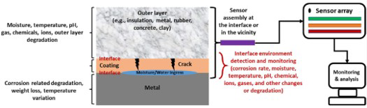
Interface corrosion is a form of localised corrosion at the interface(s) region of bilayer or multilayer structures (i.e. base metal and the outer material, for example, insulation, metal, rubber, concrete, clay) that have been affecting the chemical process and manufacturing industries, storage set-up and design of the building. In the past few decades, interface corrosion has brought a significant challenge to many industries for reasons of the high maintenance cost, system failure, which is around 40-60% of total object maintenance, and a system failure that occurs of the undetected interface corrosion [1]. Penetration and holding of water or other electrolytes at the interface region on a multilayer structure initiates corrosion and mass (precipitation) deposition. The corrosion rate is dependent on the interface localised conditions such as temperature, pH and moisture availability, which are discussed below in detail. Interface corrosion is a critical issue that is unpredictable and invisible until the outer layer is removed. Undetected interface corrosion causes product leakage, safety issues and unplanned maintenance expenses [2]. Schematics in Figure 1 show an overarching types of interface corrosion affecting different industries and monitoring various interface conditions through sensors. Moisture and chemical compounds ingest the outer materials, settles down at the interface and changes the interface conditions rapidly, which are the critical factors for interface corrosion. Change in the pH level leads to the passivation layer breaking down and accelerating the corrosion. For high operation temperature applications, moisture goes into the insulation and moving outward will finally touch a zone of the outer region of the insulation. At lower temperatures, the moisture could reach the base material (i.e. pipeline and tank surfaces, etc) in horizontal conditions. When, the equipment is in a vertical position, the moisture could come down and settle at the bottom level or underneath of equipment, leading to corrosion. The drying/wetting cycles at the interface-associated problems are a strong accelerator of corrosion damage since they provoke the formation of increasingly aggressive chemistry that can lead to the worst corrosion problems possible.
Types of interface corrosion and currently available interface condition sensing methods, including scope to use hybrid sensing and monitoring and data analytics approach (authors original image).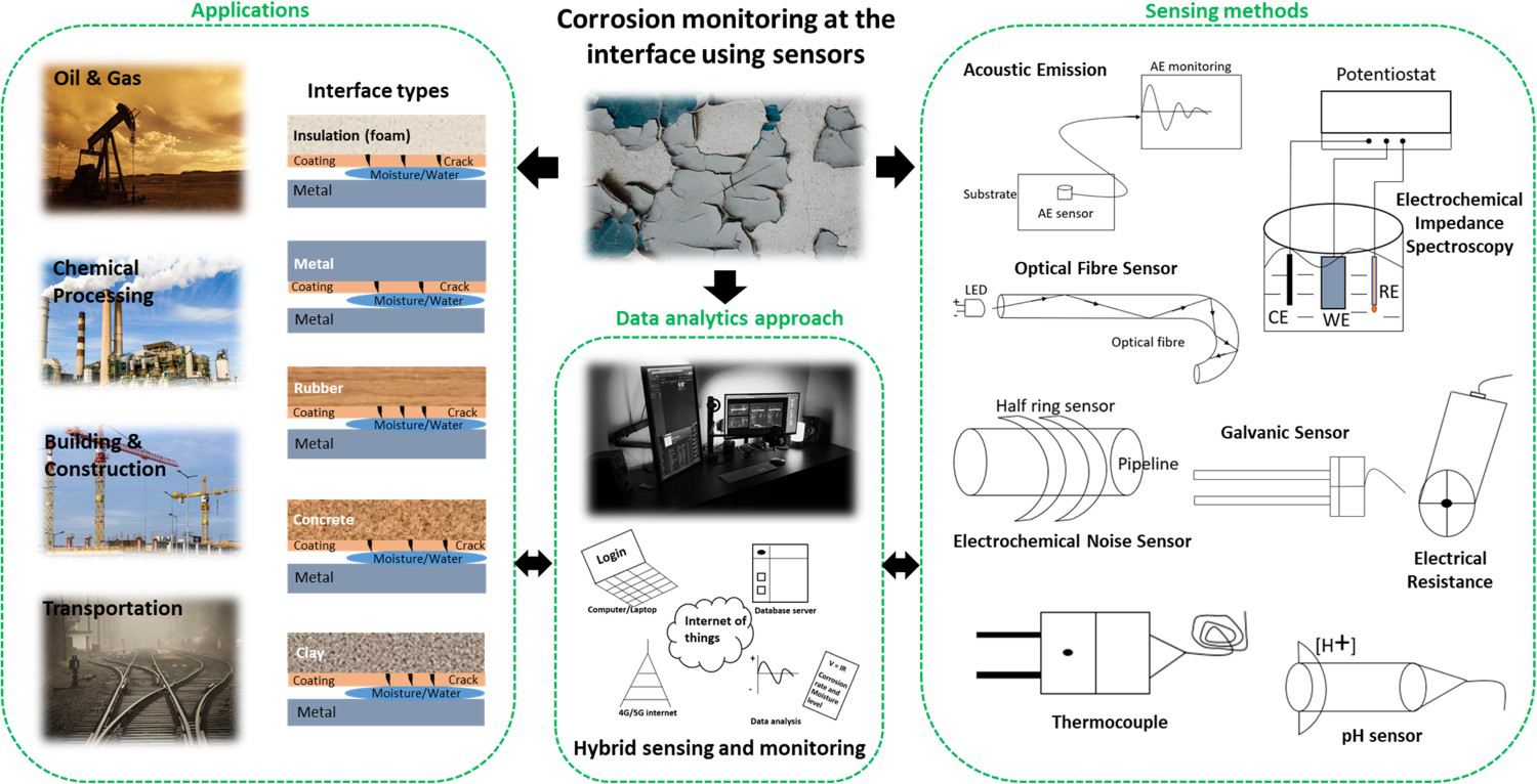
Insulation is positioned on the pipeline for various reasons including managing hot or cold temperature and optimising process efficiency (e.g. in chemical processing industry). The insulation materials are selected based on the thermal efficiency, operating environmental condition performance stability and prevention ability of corrosion under insulation (CUI). But insulation could be losing efficiency owing to long-term service period, poor installation, various environmental conditions and unexpected damages on insulation. Owing to the damages and losing efficiency of the insulation when water, chlorides and other compounds enter the insulation layer, the corrosion process begins [3]. Protective coating on the object is used to prevent the direct contact of the other objects or reactive elements because of which coatings lose their strength over a long time of service period and various environmental conditions. Currently, various interface inspection methods exist that can give quick inspection for selected conditions, (e.g. moisture, corrosion), however, the cost of the inspection system can be high if performed very frequently.
There are different kinds of inspection methods available to inspect the interface region. The basic one is a visual inspection and followed by range of other scientific methods. Also, a small probe of the ultrasonic transducer can be placed on the inner layer through partial outer layer removal. The wall thickness can be measured based on time taken by ultrasonic waves to return to ultrasonic gauge [4]. Neutron backscatter has been designed to find moisture at interface by the way of release of high-energy neutrons into the interface. The energy level of neutrons in the instrument detector gauge is directionally proportional to the moisture molecule in the interface [5]. In the pulsed eddy current (PEC) method, the thickness of wall measurement is based on eddy current diffusion time. The eddy current is generated on the inner layer via electromagnetic induction. PEC shows the average wall thickness of the pipeline, which cannot detect pitting defects on the interface [6]. Infrared thermography is a technique to measure temperatures at the interface. Infrared radiation is emitted on the object's surface and the amount of the radiation reflection is directly proportional to the temperature of the object [6,7]. Guided wave ultrasonic measurement is used to inspect the inaccessible interface conditions. Ultrasonic waves travel over the inner layer and defects on the surface makes the discontinuity in the waves [8,9]. Microwaves are used to detect water at the interface. The inner layer behaves as an inner conductor of the coaxial waveguide and cladding behaves as an outer conductor. The microwaves travel through the interface between the inner and outer layers. The limited reflection of microwaves happens when water is present at the interface level [10]. Generally, industries do interface corrosion inspection monthly, quarterly, biannually or annually based on their maintenance and safe procedure. However, if the interface conditions and corrosion can be detected and monitored using sensors then it could help make decisions about their severity levels very quickly. Advance methods of data collection, integration and interpretation of such data could provide an early warning about interface corrosion conditions which could help in planning further actions related to asset monitoring and management.
The application of sensors and sensing methods can help to access physical inputs under various environmental conditions at the interface. For example, acoustic emission (AE) sensor is used to catch the event when corrosion and crack occur in the object. The optical fibre humidity sensor is used to analyse moisture and predict corrosion initiation [11]. The galvanic sensor is another technique to sense corrosion where the potential changes indicate the corrosion process on the interface [12,13]. The temperature sensor (thermocouple) is a technique that measures the interface temperature based on the voltage creation between the temperature gradient [14]. The pH sensor indicates interface pH based on the voltage difference of the electrodes [15]. The chloride sensor finds the chloride ions penetration at the interface and shows a potential difference [16].
Other sensing methods, some of them working under the electrochemical detection techniques, such as electrochemical noise (EN) is a passive technique to sense localised corrosion behaviour in low moisture conditions and evaluate corrosion rate at the interface [17]. Electrochemical impedance spectroscopy (EIS) is a powerful technique to scrutinise the complex electrical resistance of a system and is sensitive to a material's surface phenomena and changes in bulk properties [18]. Tafel polarisation is an electrochemical technique that is applied to study the corrosion process and corrosion rate [19]. The electrical resistance (ER) method is used to detect metal loss based on electrical resistance increases owing to corrosion [21]. Currently, other sensing techniques [e.g. electromagnetic wave, U.S. 10,809,217 B2 [22] are being used to detect various conditions (mainly corrosion location and moisture) at the interface, an approach which observes specific location conditions at the interface or in the vicinity.
Preventing corrosion in the first place, and then monitoring corrosion at the interface region continuously can help avoid economical losses. As will be seen through this review, the field of interface corrosion monitoring is an important subject area in which the use of sensing methods has some advancement (both sensor types which directly measures corrosion or which measures a surrogate), and there are good examples, mainly based on laboratory systems. Knowledge of the sensor materials, their design and assembly, access to the interface regions, limitation of sensing techniques and data interpretations are important. In this review, the potential influence of materials, methods, assembly of sensor is also critically assessed.
Electrochemistry of corrosion at the interface and specifications
Corrosion is an electrochemical process that leads to the degradation of materials, and it typically requires the presence of four entity for corrosion to occur, namely, anode, cathode, electrolyte and conductive (metallic) path. The metal ions dissolve in electrolyte and electrons are released from anode material which moves through a metallic path to be reduced at the cathode. As shown in Equations (1)–(11) and in Figure 2, electron's reduction reaction occurs on the cathode surface and formation corrosion products that is free from an anode [3,22].
Schematic of an electrochemical reaction of iron metal section with water showing formation of rust and pitting (authors original image).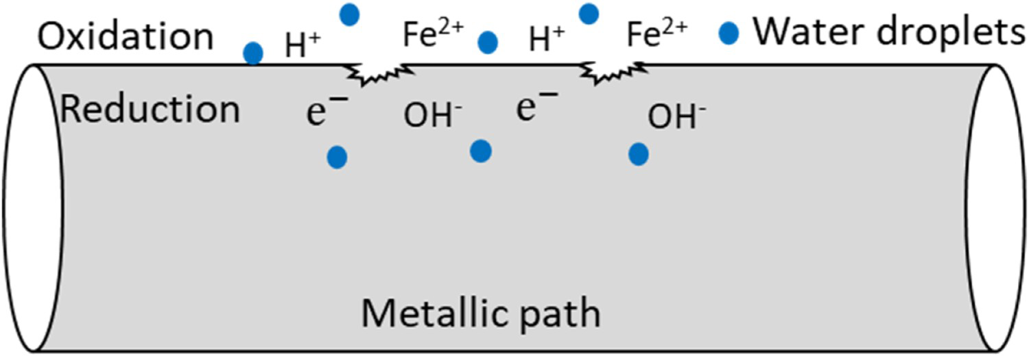
Oxidation reaction at anode:

Reduction reaction at cathode:

Reactions of corrosion productions


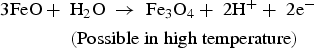
In the presence of sea water


Figure 3a illustrates the corrosion reaction under insulation (or CUI) in a pipeline structure. The pipeline may be bare or have protective coatings (such as epoxy or metallic coatings). The main reasons for CUI are moisture (water ingress), materials potential difference, temperature difference, chloride and other chemical compounds present at the interface of pipeline and insulation [17,24]. Based on insulation properties and environmental conditions, moistures are spread or gets trapped in a location which initiates the corrosion reaction. Chloride and other chemical compounds deposit on the pipeline surface or settle close to the pipeline surface contribute to the corrosion process in the interface. The temperature difference makes a real impact on corrosion under the insulation process. Moisture stays close to the pipeline when the pipeline temperature is low, and the moisture moves towards to insulation outer region when the pipeline temperature starts to increase. This event of temperature difference cycles will degrade the coating and insulation layers which will then reduce overall thermal efficiency [6]. Some of the insulation materials are compostable, lose their strength and thermal conductivity at higher temperatures. To determine the level of corrosion under insulation, it requires removal of insulation and jacketing layers. Currently, various inspection and monitoring methods are available to determine interface corrosion, environmental conditions and material loss [25]. However, each of the methods comes with limited ability to accurately detect the corrosion at the interface region.
Schematics and examples of corrosion at the interface: (a) corrosion under insulation (authors original image), (b) galvanic corrosion at pipeline interface (adapted and reproduced with permission [22] Copyright 2006, Elsevier), (c) initial passive layer crack and recycling chloride ions (authors original image), (d) corrosion at pipeline interface (reproduced with permission [23] Copyright 2018, Elsevier), (e) corrosion at bottom of the railway track (authors original image), (f) storage tank corrosion interface(authors original image), (g) corrosion on ship surface (authors original image) and (h) cavity wall insulation set-up (authors original image).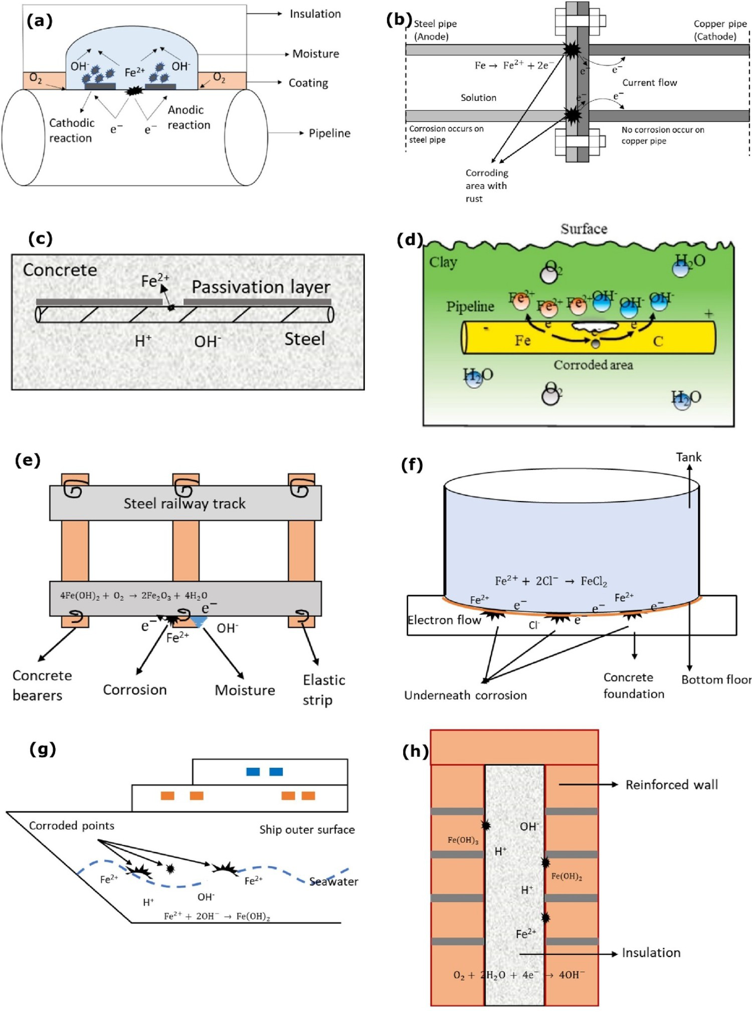
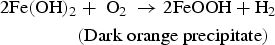
Galvanic corrosion is electrochemical process that starts when two different potential metals are directly connected (creating an interface) in presence of an electrolyte, as illustrated in Figure 3b [22]. Combination of temperature and moisture levels at the interface increase the corrosion reaction. Electrons move from more active metal (anode) to more noble metal (cathode) [26]. Galvanic cell builds when two different potential metals are linked [e.g. iron (−0.440 V), copper (+0.334 V) with respect to the hydrogen reference electrode]. Potential variations between those two metals are the driving force for corrosion. Iron ions (Fe2+) travel from anode to cathode through the electrolyte. Hydrogen ions (H+) are released from the cathode. In the cathode, Fe2+ ions merge with OH− ions to form the iron hydroxide, Fe(OH)2. In galvanic corrosion, the visibility of the corrosion at the interface is very low. Specified inspection or monitoring methods are required to inspect the interface condition frequently to avoid system failure. The polymer insulation materials or protective coatings between the interfaces can avoid the direct contact of the different materials and stop the electron's transfers. Selection of the materials can help to reduce the potential difference of the materials and minimise the driving force [22,27]. In general, galvanic corrosion cell does not need any external power source. It is an advantage to make a galvanic cell underground with a soil interface between the pipeline and high potential materials to prevent the corrosion on the pipeline. This method is generally known as the sacrificial anode system in cathodic protection.
Figure 3c illustrates the corrosion on the reinforced concrete [28]. There are some similarities, however, it is necessary to acknowledge that corrosion of reinforced concrete is different to that outside of a pipe or process vessel with or without insulation or coating. Reinforced concrete is a versatile, strong, long durable composite construction material. In some situations, it loses strength rapidly and collapses owing to various reasons such as poor materials selection, wrong way of design and construction method, awful environmental conditions. Broomfield [29] mentioned about corrosion in reinforced steel. Reinforced concrete contains a high level of calcium, sodium and potassium oxides which are alkaline hydroxides. These alkaline hydroxides make a concrete alkaline (pH range from 12 to 13). High alkalinity condition forms a passive layer over the steel and protects it from corrosion attack. The reinforced concrete cracks start at a specific place owing to mechanical loading and thermal shrinkage. The chloride, water, oxygen and carbon dioxide enter the crack and settle down on the steel. Carbonation of concrete and chloride attack demolishes the passivation layer which leads to corrosion (note: the process of alkaline hydroxide reaction with carbon dioxide gas is called carbonation). The chloride-induced corrosion on reinforced steel is a multi-stage process. Chloride diffuses randomly on the concrete from various sources through concrete cover and accumulation of chlorides on the reinforcement. It then breaks the passive layer of the steel and corrosion initiates and propagates. The reinforced interface corrosion can be mitigated by making sure functional changes at the concrete-steel interface and using corrosion inhibitors to delay the depassivation of steel [29–32].
To layout a pipe, various types (i.e. aboveground, underground) of pipeline assembly or supports are used. Failure in aboveground pipeline can happen for various reason, but the leading causes is corrosion at the interface of pipeline and support. Especially, the I-beams and other flat surface supporting frames are problematic structures that give a place to accumulate moisture and other contaminants in support interface and the support frame is the primary one of the reasons for corrosion begins [33 35]. A potential difference between support and pipeline makes a galvanic corrosion cell. Long-term moisture or water trap between support and pipeline reduces the strength of the pipeline coating. Placing the insulation or rubber gasket at the support interface can prevent the direct contact of the pipeline and support. Pulsed eddy current, ultrasonic guided waves and radiography methods are used to inspect the support interface conditions [33,35]. In an underground pipeline, soil or clay layer surrounds the pipeline outer surface area and corrosion can begin at the interface of pipeline surface and soil or clay, as shown in Figure 3d [23]. While the bottom soil gives good support to the pipeline, the primary crack can begin at the bottom of the pipeline [37], and any damage in pipeline coating can provide ways for water to react with the pipeline surface. The physicochemical property of soil makes a direct impact on the pipeline surface which are ion contents, moisture, resistivity and pH. The interface corrosion rate can be high at the conditions of high moisture, low resistivity, and the intergranular morphology and crack are sharp in high pH [37,38]. An appropriate pipeline coating can help reduce the direct contact of the soil which can delay the corrosion. On the next level, using a cathodic protection system to prevent the pipeline through an external power and anode source is also possible.
Railway track works under various environmental conditions like seacoast environment, various humidity levels, the different temperatures of the atmosphere, and tunnel area. Soil resistivity is a major element in underground corrosion. The resistivity of soil is based on soil moisture and dissolved ionic salt concentrations. In soil, the presence of a high amount of salt directly reduces soil resistivity. In low soil resistivity, the degradation of railway track is fast which embeds in soil. The rail movement which introduces a type of cyclic loading may add to corrosion fatigue failure of the railway track [39,40]. The presence of sodium chloride, potassium chloride and other chlorides form of electrolytes on railway track induce oxygen to react with the railway track which leads to premature track failure [40], as illustrated in Figure 3e. Corrosion of railway track also depends on the accessible amount of oxygen on metal surface and the flow of oxygen based on the presence of humidity on the metal surface. High humidity, oxygen availability and low soil resistivity lead to the corrosion process rapidly [41]. The stray current corrosion is a critical issue in the railway. The stray current leakage is high in low soil resistivity areas and the leakage of DC power from operating transit systems is significantly high compared to AC transit systems. The current travels to unintended bath owing to low resistivity through railway structure, and it makes material degradation (through electron loss) where it leaves from the structure [42,43]. Application of protective coatings are a common means for railway structure corrosion mitigation. But it cannot provide long-term service owing to the impact of several structural, metallurgical and environmental conditions that affect the behaviour and strength of the protective coatings. For the stray current mitigation, use of rail boots, dielectric polyurethane, cathodic protection, isolating the rail in troughs is utilised to control the stray current leakage [43,44].
Storage tanks (underground or aboveground) are used to reserve various chemical compounds in an appropriate environment condition worldwide. The environmental conditions of underground including the soil resistivity start and accelerate the corrosion process. The external corrosion occurs on the tank surface when the protective coatings start to deteriorate [45]. In aboveground tank, major part of the structure is exposed above the ground level and the tank bottom sits on soil or a foundation. Figure 3f illustrates the corrosion between the tank bottom plate and its foundation [46], a space between the tank outer surface and insulation materials. Moisture, high temperature, chlorides between the interfaces accelerate the corrosion. Sludges (which usually comes from the fluid inside and which deposits on fluid-side of the tank bottom) also promote pitting corrosion, and the corrosion reaction can be at a high level because it keeps the moisture for a long time, leading to tank failure and materials wastage [46,47]. The underground storage tank external surface corrosion can be mitigated by protective coatings which can prevent the tank surface from atmospheric corrosion. The cathodic protection system can offer good corrosion mitigation to the external tank surface through an external power source anode system or sacrificial anodes. Insulation in the inlet and outlet of the storage tank can be used to stop stray current corrosion interactions [48]. The protective coatings, sealing the gaps around the tank bottom, and concrete foundation can help eliminate the water entry, storage of other contaminates between the storage tank bottom and concrete foundation. Installation of cathodic protection system or impressed current method can provide an effective protection at the tank bottom for a long duration. Volatile corrosion inhibitors (VCI) can also prevent the vapour transmission from concrete bed to tank bottom surface, which is available as a powder, foam, thin liquid solution and is effective in the sand layer as well [49,50].
Corrosion and corrosion fatigue are an important reason for significant numbers of ship hull damage. The sea water properties are different in various locations and depths such as temperature, oxygen contents, pH level, corrosive minerals and chloride compounds. Atmospheric corrosion happens on parts of the ship which is not immersed in the sea water. A passivation layer of steel materials cannot withstand these conditions. A flow of sea water accelerates the corrosion on ship hulls [51], as illustrated in Figure 3g. The distribution of crack, corrosion growth depends on the various phenomena in the environments. Each damage and cracking should be properly monitored and rectified, which can help to prevent catastrophic failure. Especially for bulk carriers and tanker structures, the monitoring of corrosion and fatigue are very important to stop drastic accidents [22,52 54]. Localised interface corrosion is a very small attack compared to the general corrosion surface. But it plays a vital role in the strength of a ship and maintenance cost. Repair or replacement of corroded ship bottom is not an economical process [55]. Various ways to mitigate corrosion on ship hull is based on the selection of ship construction materials, application of protective coatings, cathodic protection, inhibitors and overall corrosion management [56].
Considering structural building materials interface, as an example, Figure 3h illustrates the cavity wall insulation set-up, and the method is used to hold the heat and prevent heat loss on the building walls which can potentially reduce the heat loss by around 40% through the walls [57]. The insulation holds the water between the outer wall and insulation surface which deteriorates the outer wall surface and corrosion happens on the steel ties. The presence of acidic elements accelerates the reduction of the wall strength and absorbs high-level moisture [58,59].
The above summary clearly distinguishes each interface corrosion type with its environmental conditions. Various protecting layers are used on the structure and mitigate interface corrosion, which includes (a) protective coatings, (b) water resistance insulation, (c) vapour barrier, (d) covering/jacketing and (e) rubber flange, etc. Figure 4 illustrates electrochemical reaction at various interface types and conditions. The protective coatings physically prevent the direct contact of water and other contents to the object's surface [60]. Insulation is a primary safeguard for the object to avoid unwanted reactions, damages. Insulation covers the complete or specified area of the object based on industrial requirements and environmental conditions. The insulation has a high resistivity to stop moisture penetration [61]. The vapour barrier is a good preventing method to stop moisture enter insulation from outside [60]. Covering is the first layer of prevention that stops the direct contact of other objects with insulation or vapour barrier. Covering is exposed to local environmental conditions which could be damaged easily. Rubber can be a non-conductive layer between the two metals (e.g. submarine structure), metal-solid to prevent the direct connection and prevent the galvanic cell formation.
Schematic of electrochemical reactions leading to corrosion and degradation at various interface types (authors original image).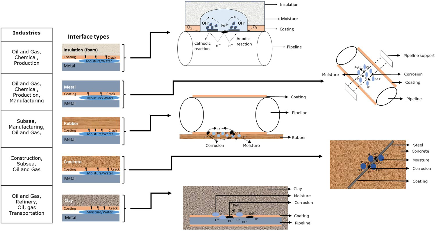
Interface corrosion sensing and monitoring methods
This section presents examples where various sensors (and detection methods) have been used to detect and monitor corrosion at the interface. This includes both sensor types which directly measures corrosion, and which measures a surrogate. This section briefly describes the sensing methods used to detect and monitor corrosion at the interface and then presents relevant examples.
Summary of sensor-based interface corrosion conditions detection and monitoring.

Electrochemical noise
Electrochemical noise (EN) is a passive technique to sense localised corrosion behaviour in low moisture conditions and evaluate corrosion rate at the interface. Electrochemical current noise (ECN) and electrochemical potential noise (EPN) methods are used to analyse various records to determine the interface corrosion behaviour. These two EN methods can be run separately or simultaneously. The current noise can measure the current variation between the working electrode and the counter electrode. The current variations can be higher in the wet interface condition compared to the dry interface condition. As shown in Figure 5a, the potential noise fluctuations are measured between the working electrode and the reference electrode potential noise [17,80,82 84].
Examples from electrochemical noise (EN) sensing method of corrosion at the interface: (a) corrosion analysis of potential and current noise (reproduced with permission [80] Copyright 2009 Elsevier), (b, c) arrangement of the EN sensor on the pipeline and standard deviation on the wet and dry cycle (reproduced under the terms of the creative Commons CC BY license [17] Copyright 2020, Springer Nature), (d, e) electrodes under insulation (reproduced with permission [74] Copyright 2017, Elsevier) and (f) scheme of the electrochemical noise system (authors original image), (g) electrochemical noise system measurement (reproduced with permission [81] Copyright 2016, Elsevier).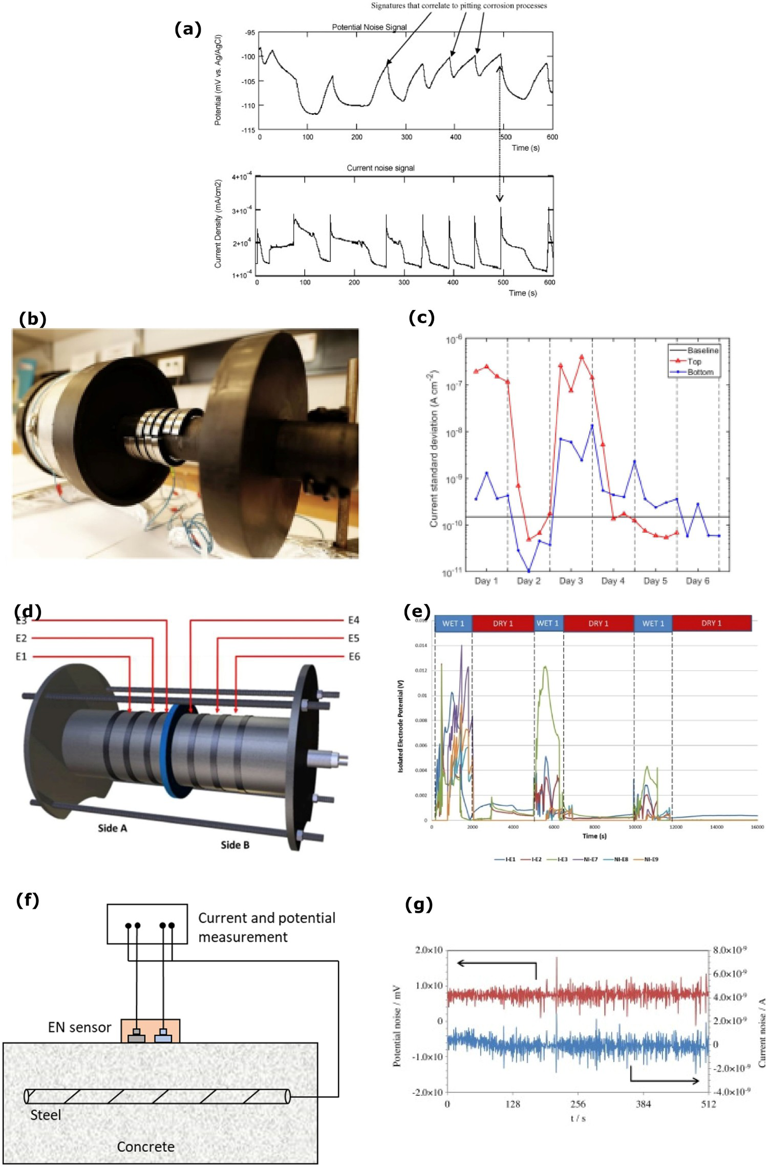
The combination of electrochemical potential and current noise is more powerful than the individual measurements. The localised corrosion can be significantly accelerated when the working electrode potential crosses the pitting corrosion potential. The initiation of pitting corrosion releases high current noise and the pitting corrosion propagation noise differs from the initial noise. The advantages of EN methods are that it can measure the potential and current noise simultaneously and does not use external applied potential signals. However, the disadvantages are that the potential and current noise signals are not suitable to directly coordinate signals to determine the specific location of the localised corrosion. Also, when the working electrode is polarised above the pitting corrosion potential (i.e. when localised corrosion process and mechanism changes), the EN methods are not suitable. These are some of the reasons to stop using the EN methods [17,80].
EN methods were developed with the two working electrodes, zero resistance ammeter, reference electrode and potentiometer to measure potential and current simultaneously. Caines et al. [74] explained the EPN method to predict the type of corrosion and corrosion rate under insulation conditions based on the potential changes. EN is a promising tool to find localised corrosion including in low moisture conditions. The current fluctuations between the metal and electrolyte interface generated by corrosion can be spontaneously recorded through the sensor. ECN sensor contains two half-ring steel samples which are placed on the top and bottom of the pipeline surface under mineral wool insulation. The sensitivity distance range of such sensor is uncertain. The corrosion rate and mechanism of the top and bottom pipeline sections can be monitored through the ECN sensor. The measured standard deviation on the ECN sensor explains the wet and dry conditions and corrosion intensities under the insulation, as shown in Figure 5b,c. Further experiments are needed to quantify the corrosion rate from the standard deviation. This is one of the limitations of ECN sensor usage. Machine learning, random forest (RF) and linear discriminant analysis (LDA) can be used to identify the pitting and uniform corrosion on the interface from the ECN data. In such measurements, the mineral wool insulation is typically soaked in sea water overnight before installation on the pipeline so that drying process could start. On day 3, 1000 ml of the sea water is added to the insulation by syringe. The current standard deviation measurement changes based on wet and dry cycle of the insulation conditions. On day 1, the top sensor could show a high level of the standard deviation, which decreases over the next day. By adding additional sea water, it can increase corrosion activity on top and bottom sections. Over time, the drying insulation conditions decrease the current standard deviations. This means, ECN data can provide interface behaviour based on wet and dry conditions, however, further research are needed to determine the corrosion rates [17,85,86].
EPN method is used to monitor corrosion under insulation conditions instead of linear polarisation resistance to take advantage of the passive technique. Three electrodes are placed over the pipeline surface and covered with insulation, as shown in Figure 5d,e. The third electrode acts as a reference electrode and measures potential difference of the remaining electrodes. Water ingress under insulation induces the potential difference as the dry condition progress. The potential difference helps in identifying the type of corrosion. The continuous potential difference indicates the uniform corrosion under insulation and sudden potential changes show the localised corrosion. However, a high number of the electrodes need to be placed on the pipeline to monitor whole pipeline insulation interface [74,83].
Most common electrochemical methods such as Tafel polarisation, linear polarisation resistance and electrochemical impedance spectroscopy (EIS) can show excellent results in the potential monitoring and corrosion rate estimations. But these methods do not provide the type of corrosion details. However, EN method can be used to measure the corrosion and identify the corrosion type of the reinforced steel in concrete [87,88]. By using EN method, Hardon et al. [89] demonstrated reinforced steel corrosion behaviour and corrosion rate while testing in the environment of salt-contaminated concrete. In such experiments, two concrete blocks are placed in two different electrolytes for a long time and monitors corrosion at the interface. At the centre of block, a guard ring is used to prevent current leakage and observes concentric current distribution. The representation of EN sensor placement to the concrete steel corrosion measurement and measures potential and current is shown in Figure 5f,g. The current and potential variation are measured from the reinforced steel to the counter electrode with respect to the reference electrode on mortar. However, it does not reflect the exact condition at the interface. The thickness and resistivity of concrete affect current and potential measurements and indicate wrong corrosion types with delay response [90].
Tafel polarisation
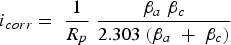
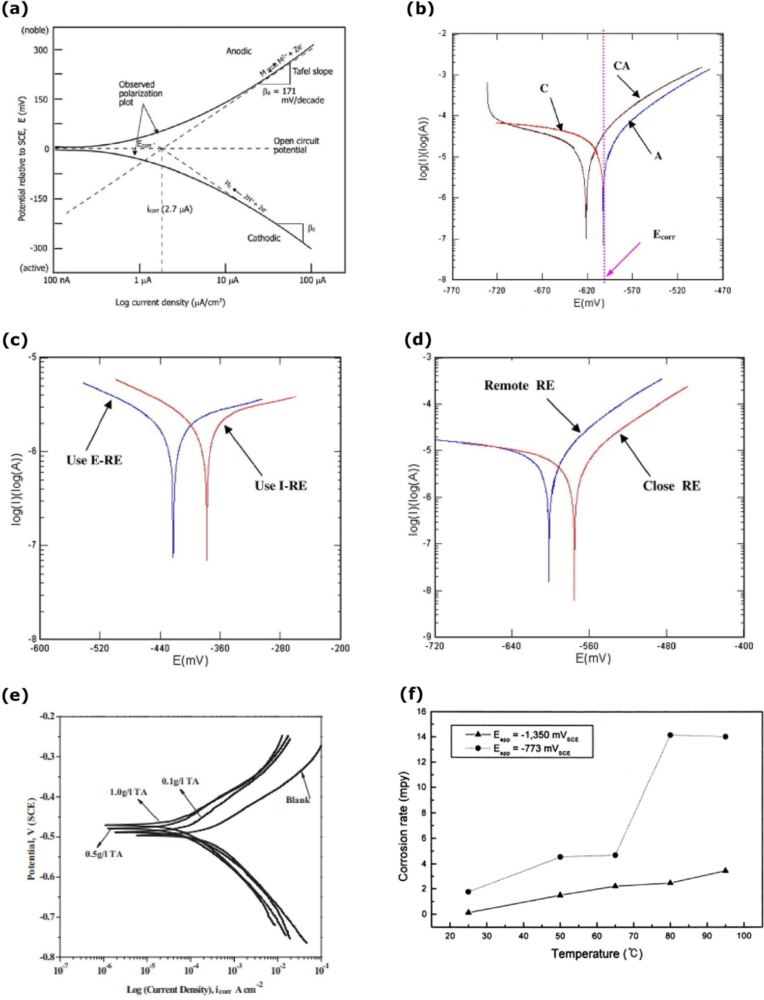
The polarisation technique contains various methods such as Tafel polarisation, linear polarisation resistance, cyclic polarisation and potentiodynamic measurements. Tafel polarisation is a simple way used widely to determine the material's corrosion rate. It has high importance in the materials corrosion behaviour and corrosion rate investigations which is a faster experimental method of active DC potential electrochemical technique. Polarisation curves are measured through the standard two/three-electrode system. In the large potential region, the reactions of the object are represented in a graphical plot of potential vs. log current density [Figure 6(a)]. It has the anodic region with slope (βa) and the cathodic region with slope (βc). The linear regions of anodic and cathodic regions are extrapolated to determine the corrosion potential (Ecorr) and corrosion current density (icorr). In many cases, cathodic curves may not be observed in linear region which happens when oxygen in the solution exists leading to diffusion-controlled oxygen concentration limiting condition compared to hydrogen cathodic reaction at the interface. The anodic and cathodic curves show behaviour of the interface conditions. The corrosion rate of objects determines from the corrosion current density by using Equation (12), where CR is corrosion rate in millimetre per year (mmpy) Equation (13), K is the constant to define the units of corrosion (3272 for mmpy), EW is the equivalent weight (g/mol), d is the density (g/cm3) and Rp is the polarisation resistance Equation (14). The corrosion current density can be determined by using the Stern-Geary Equation (13). The passivation layer on the object surface prevents the reaction with the environment and at this level, the current density is maintained at a steady level. When the passivation layer breaks, corrosion reaction begins with current density changes [22]. The advantages of the Tafel polarisation are faster experimental technique, accurate explanation of the corrosion kinetics on the reaction [22,94–97].
Examples from Tafel polarisation method of corrosion at the interface: (a) Tafel polarisation from (reproduced with permission [22] Copyright 2006, Elsevier), (b) Tafel polarisation, (c, d) corrosion potential based on reference electrode location (reproduced with permission [91] Copyright 2008, Elsevier) and (e) efficiency of the inhibitor on the interface (reproduced with permission [92] Copyright 2015, Elsevier) and (f) insulated pipeline corrosion rate at various temperature (reproduced with permission [93] Copyright 2001, Elsevier).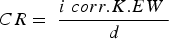

Baweja, Roper and Sirivivatnanon [98] investigated the corrosion of reinforced steel in high chloride conditions by the Tafel polarisation technique. Localised reinforcement corrosion was found with high chloride conditions. The reinforced concrete slab size of 300 × 300 × 56 mm was immersed in the 3% NaCl solution and kept in the laboratory condition at 50 ± 5% relative humidity and 23°C. The corrosion potential of the reinforced steel decreased with the reduction of the water–cement (W:C) ratio. The low (W:C = 0.65) ratio took a longer time for the corrosion. It was observed that the reinforced corrosion increases linearly with the increase of exposure area closure to the chloride conditions.
Ahmad and Bhattacharjee [75] explained the arrangement of Tafel experiment to measure the corrosion rate of the reinforced steel in sea water condition. The reinforced steel was enclosed with concrete and the titanium ribbon as a counter electrode was placed 10 mm away from the steel bar in the concrete. In the reinforced steel (working electrode) one end relates to the sleeved wire and the other end was sealed with epoxy. The concrete block was impressed in the sea water and the saturated calomel electrode was used as a reference electrode in the sea water. The polarisation range is −120 to +120 mV concerning the E OC, shown in Figure 6b. The corrosion rate of the reinforced steel under the concrete was 0.098 mm/year. The reference electrode was placed away from the interface condition which affects the working electrode corrosion potential measurements. The polarisation of the reinforced steel and polarised reinforce steel potential takes a longer time to come back to the original potential level owing to concrete which significantly restricts the movement speed of ions and molecules. The high current density required to prevent the reinforced steel interface corrosion on the concrete structure on cathodic protection method [91]. The reinforced steel corrosion behaviour on the concrete structure in sea water, and the efficiency of the corrosion inhibitor on the reinforced steel-concrete interface have been investigated using Tafel polarisation method [99,100].
Reference electrode location is important to measure the corrosion rate and monitor the corrosion of the sample. Ag-AgCl electrode can be embedded in the concrete structure at 5 mm from the steel bar. In such measurement, it can act as internal reference electrode and the saturated calomel electrode can be placed on the outer side of the concrete structure as an external reference electrode. In such measurement, the concrete block and external reference electrode are soaked in sea water and then measured the corrosion potential. As shown in Figure 6c, the internal electrode condition shows high corrosion potential than the external reference electrode position. In further experiments while using Tafel polarisation method for corrosion rate analysis, the reference electrode was placed close (3 mm) to the steel and remotely placed 1.2 mm away from the sample. The corrosion rate of the sample was high (0.136 mm/year) in close reference electrode condition compared to the remote reference electrode location owing to the ohmic drop between the reference electrode and sample influences the potential measurement drop. The corrosion potential was −0.576 V in close reference electrode level and −0.602 V in the remote reference electrode condition, as shown in Figure 6d. This study proves the importance of the reference electrode location for the measurement, and to get a highly accurate measurement of the interface conditions, the reference electrode needs to be placed on the interface condition [91].
The Tafel polarisation method can study the corrosion inhibition effect [e.g. Figure 6(e)] of the steel and HCl solution interface [e.g. [92]]. In such example, a mild steel working electrode was kept in the 1M HCl electrolyte solution with the platinum counter electrode and saturated calomel electrode at 30°C. The tannic acid (TA) was added with three different amounts (i.e. 0.1, 0.5 and 1.0 g/l TA) in the HCl electrolyte, and the corrosion rate was measured using the Tafel polarisation method. It was observed that the efficiency of the inhibition was high for 1.0 g/l TA. It was also observed that the corrosion rate decreased with an increase in inhibition concentration of the electrolyte. The corrosion potential positive shift on the graph explains the strength of suppressing the anodic reaction on the working electrode [92]. Similarly, Saraswathy and Karthick [101] studied the effect of eco-friendly zinc phosphate with nano-silica coating on the reinforced steel to prevent interface corrosion in a 3.5% NaCl environment through the Tafel polarisation. It was concluded that the zinc phosphate with nano-silica coating reduces the corrosion rate about 1.5-2 times of coated reinforced steel compared to plain reinforced steel, which can be used as a protective coating to prevent interface corrosion in a cost-effective and eco-friendly way. Tafel polarisation method can also be used to study the cathodic protection criteria of the thermally insulated pipeline in the soil. In such investigation, the pipeline is covered with insulation and reference, counter electrodes are placed away from the interface in soil. The protection potential increases with the temperature increase in soil conditions. To protect the thermally insulated pipeline, it requires high current density compared to the coated pipeline owing to insulation restricting the ions transmission. Low protection potential did not provide adequate protection to pipeline and corrosion rate rises. The thermally insulated pipeline can protect the way of cathodic protection in polarisation potential −1350 mV up to 95°C temperature, as shown in Figure 6f. The performance of the corrosion inhibitors under the insulation condition have also been studied by Tafel polarisation [93].
Electrochemical impedance spectroscopy
Electrochemical impedance spectroscopy (EIS) has many applications, such as investigating the interfacial processes, geometric effects, applications in power sources of batteries, interface corrosion, object coatings and paints. To understand the impedance behaviour in electrochemistry, it is necessary to know about basic electrical circuits (Figure 7) (Equations (15)–(17)) [102 104].
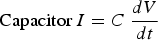
Basic electrical circuits for electrochemical impedance spectroscopy (EIS): (a) resistor (Z = R (Ohms), 0° phase shift), (b) capacitor (Z = −j/ωC (Farads), −90° phase shift) and (c) inductor (Z = jωL (Henrys), 90° phase shift) (authors original image).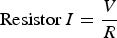
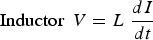
EIS is usually measured by applying an alternating current (AC) frequency to an electrochemical cell and measuring impedance through the cell. It is a powerful technique to apply in a wide range of the electrochemical system to determine the interface reaction on the different layers. In three-electrode cell, the working electrode, counter electrode and reference electrode work under potentiostatic or galvanostatic control which analysis the corrosion, moisture and interface conditions. In the two-electrode system, the counter electrode works also as a reference electrode. The counter electrode surface area should be large than the working electrode to maintain reaction equality. The Kramers–Kronig (KK) transform check to be made on the validity of an impedance data set acquired for a linear system over a wide range of frequencies [63,104]. The impedance of the working electrode controls the overall impedance which is significantly higher compared to the counter electrode. AC frequency flows over the working electrode [18]. The external AC electric field applied to the working electrode induces the intrinsic atomic and molecular charges to polarise as per the applied electrical field. Material degradation and absorbed moisture molecules makes an impact on the impedance of the electrode. EIS data can be presented as a bode (simple) plot or a Nyquist (complex) plot (illustrated in Figure 8). The bode plot is the combination of AC frequency, phase and amplitude which explains the materials phase and magnitude changes in each frequency level. The Nyquist plot determines the resistance of material from high frequency to low-frequency range [64,105,106].
Bosch [107] developed a model to distinguish the impedance response based on the surface conditions, which can help to understand the impedance behaviour clearly when the corrosion products deposition on interface conditions. The model showed impedance measurement phase shift based on the stress corrosion cracking in stainless steel in an aqueous environment at room temperature. Kim et al. [108] demonstrated the EIS measurement of double-layer capacitance analysis based on the bacteria adhesion and biofilm formation. EIS has also been used to study metal and coating interface conditions, such as adhesion and corrosion. In this example, bare steel and NaCl pre-treated steel plates were coated with the 20 µm thick of epoxy coating. The NaCl pre-treated steel plate showed loss of coating adhesion and materials degradation at the interface owing to the steel plate surface being contaminated with the NaCl pre-treatment before the epoxy coating [109]. EIS has also been used to investigate corrosion of organic coating deposited on metal surface and resistance of the coating to aqueous and ions transport. In such investigation, visually non-damaged coating showed corrosion underneath the coating owing to the water molecules and oxygen penetrating through tiny pores or pathways. Initial impedance check does not indicate any corrosion attacks owing to proper surface treatment of the working electrode which blocked the interface and preventing the anodic potential shift [110].
Electrochemical impedance spectroscopy (EIS): (a) Nyquist plot and (b) Bode plot (authors original image).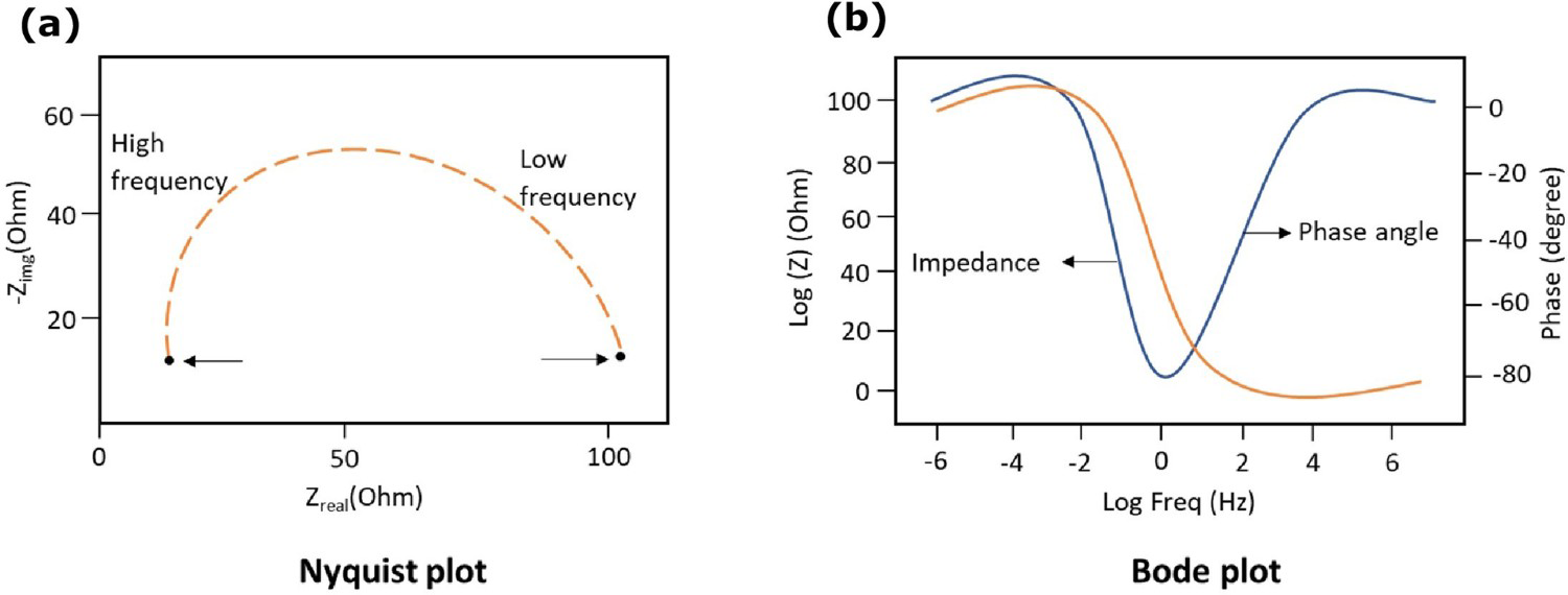
As shown in Figure 9a, EIS has been used to study the interface of insulation and electrolyte, and the strength of the insulation [76]. In such testing, an interdigitated electrode (IDE) was coated with the parylene C as an insulation with 50, 100, 200 and 500 nm thickness. IDE was soaked with the phosphate-buffered saline (PBS) in the glass jar. The soak test set-up was maintained at 90°C for 45 days. The impedance could not measure clearly in the low frequency range owing to the measuring limitation of the instrument. Figure 9b shows impedance response based on different insulation layer thicknesses at 1080 h (45 days). Immediate impedance drop initial frequency range shows that the electrolyte diffuses on the insulation layer once the interdigitated electrode (IDE) structure is impressed on the electrolyte. The impedance decreases, and the phase angle move towards zero, confirming that the electrolyte and ion diffuse on insulation. The insulation thickness of 50 and 100 nm coating samples impedance shows that IDE makes direct contact with the electrolyte, confirming that parylene C coating could not act as an insulator. On the other one, with 500 nm coating thickness, the impedance decreases gradually over the soaking period on the electrolyte, which implicates the gradual electrolyte diffusion on the coating in the testing period. EIS data reveals that the parylene C coating can be used in limited electrical applications only, and further modifications are required to achieve sufficient insulation [76].
Electrochemical impedance spectroscopy (EIS) testing of corrosion at the interface: (a,b) Experimental set-up and impedance measured in 1kHz frequency (reproduced with permission [76] Copyright 2014, Elsevier), (c,d) reinforced steel corrosion measurement by EIS (reproduced with permission [111] Copyright 2016, Elsevier) and (e) electrode arrangement (reproduced with permission [112] Copyright 2020, Taylor & Francis).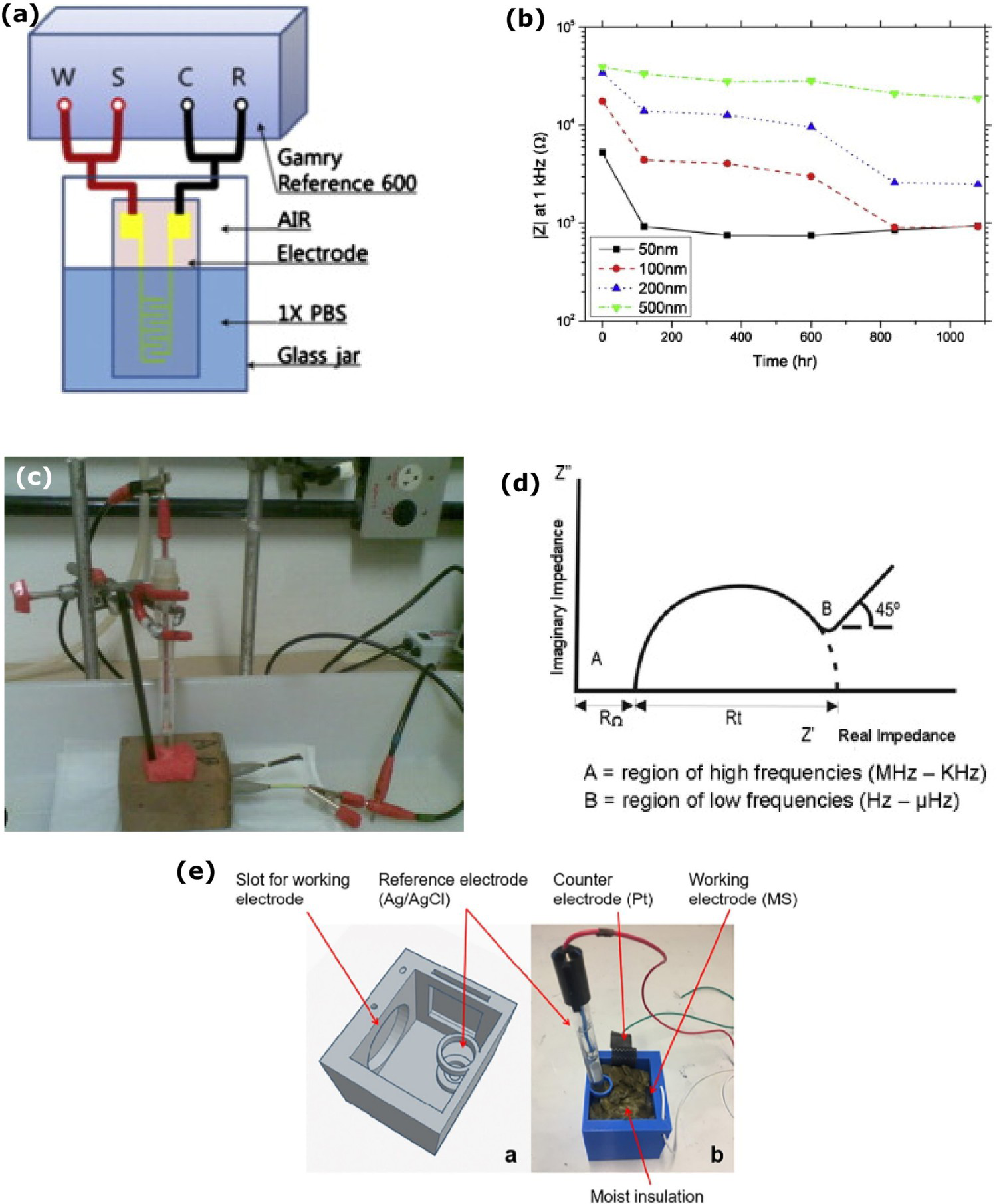
Hachani et al. [113] studied the concrete/steel interface behaviour by EIS. It can monitor several features, such as the presence of surface films, interfacial corrosion and mass transfer phenomena. Ribeiro and Abrantes [111] experimented with the reinforced steel in the concrete works as a working electrode, and the reference electrode was placed outside of the mortar surface, as shown in Figure 9c,d. In the Nyquist diagram, the initial high-frequency region indicated a passive layer on the steel which prevented the corrosion reaction with high impedance. Semicircle on the intermediate frequency range indicated that the corrosion products are formed at the interface. In the low frequency, the straight line showed the diffusion of oxygen. The ohmic drop was associated with the reference electrode placement away from the interface, which affects the accuracy of the measurement [114].
Corrosion and corrosion rate under insulation conditions can be monitored with EIS. As demonstrated by Pojtanabuntoeng et al. [115], half-ring specimens are placed top and bottom of the pipeline as a working electrode. Insulation and jackets are placed on top of the half-ring. The presence of the water at the interface between the half-ring electrode and insulation shows the double-layer capacitance, and the impedance decreases based on water rising at the interface. The limitation of this method is that the monitoring range at the interface are small but adding more electrodes could provide a high level of interface monitoring.
As Cao et al. [112] demonstrated, mild steel and insulation interface corrosion reaction is affected by the moisture level, which EIS can measure. The working electrode was placed on one side of the electrochemical cell in such measurement. In such measurement the reference and counter electrodes are placed away from the working electrode, and the interface was filled with insulation, as shown in Figure 9e. The insulation was wetted with various per centage of 10%, 30%, 50% and 70% of 0.6 M NaCl solution and 100% 0.6 M NaCl solution (without insulation). The moisture level increases on the insulation, enhancing the working electrode surface contact with higher oxygen concertation, reducing the impedance on the interface and increasing corrosion. The corrosion rate and metal loss increase with the electrolyte volume % increases on the insulation.
Galvanic sensor
Galvanic sensor is a passive method to monitor the corrosion system which has high sensitivity and typical method for operators. Galvanic sensor is a combination of the two different metals which generate the electrical current by a natural potential difference [12]. A schematic diagram of galvanic sensor measurement is shown in Figure 10a. The presence of electrolyte connects the two different materials and gives a pathway for reaction and electron transfer. The continuous electron transfer from one metal to another metal shows the measurement's potential changes. The sensitivity of the sensor is affected by oxygen concentration, temperature and the passive layer on metal [13]. Coating, cathodic protection, coal-tar lining and cleaning are various methods to prevent corrosion on the external and internal pipelines. However, corrosion still can occur on the surface. The reliable galvanic sensor can provide corrosion monitoring of the pipeline and can evaluate the performance of the corrosion protection. Galvanic sensor connects to inner side of the pipeline through electrolyte solution to determine the corrosion on the interface between the solution and the object's surface [12]. Initial polarisation drops indicate the formation of galvanic cells with sensor and pipeline. When the reaction reach equilibrium, a stable double layer forms on the sensor and the galvanic current remains stable. Galvanic current then starts to drop slowly when the passive layer breakdown and the initiation of corrosion reaction and the oxidation products are attached to the anode surface. Galvanic current is linear to the electrolyte temperature, the concentration of dissolved oxygen, and the flow rate of the liquid. The increase in temperature accelerates the molecular thermodynamic movement and makes the diffuse coefficient rise. The galvanic sensor is a reliable detection tool for internal pipeline corrosion monitoring, and it is stable in the intrinsic aggressive environment, database accumulation in multifarious corrosion environment [12,13,116 118].
(a) Schematic diagram of galvanic sensor measurement (authors original image), galvanic sensor examples for corrosion analysis at the interface: (b) galvanic current relationship with dissolved oxygen and temperature (reproduced with permission [12] Copyright 2008, Elsevier) and (c) galvanic sensor on under insulation pipeline (reproduced with permission [77] by email).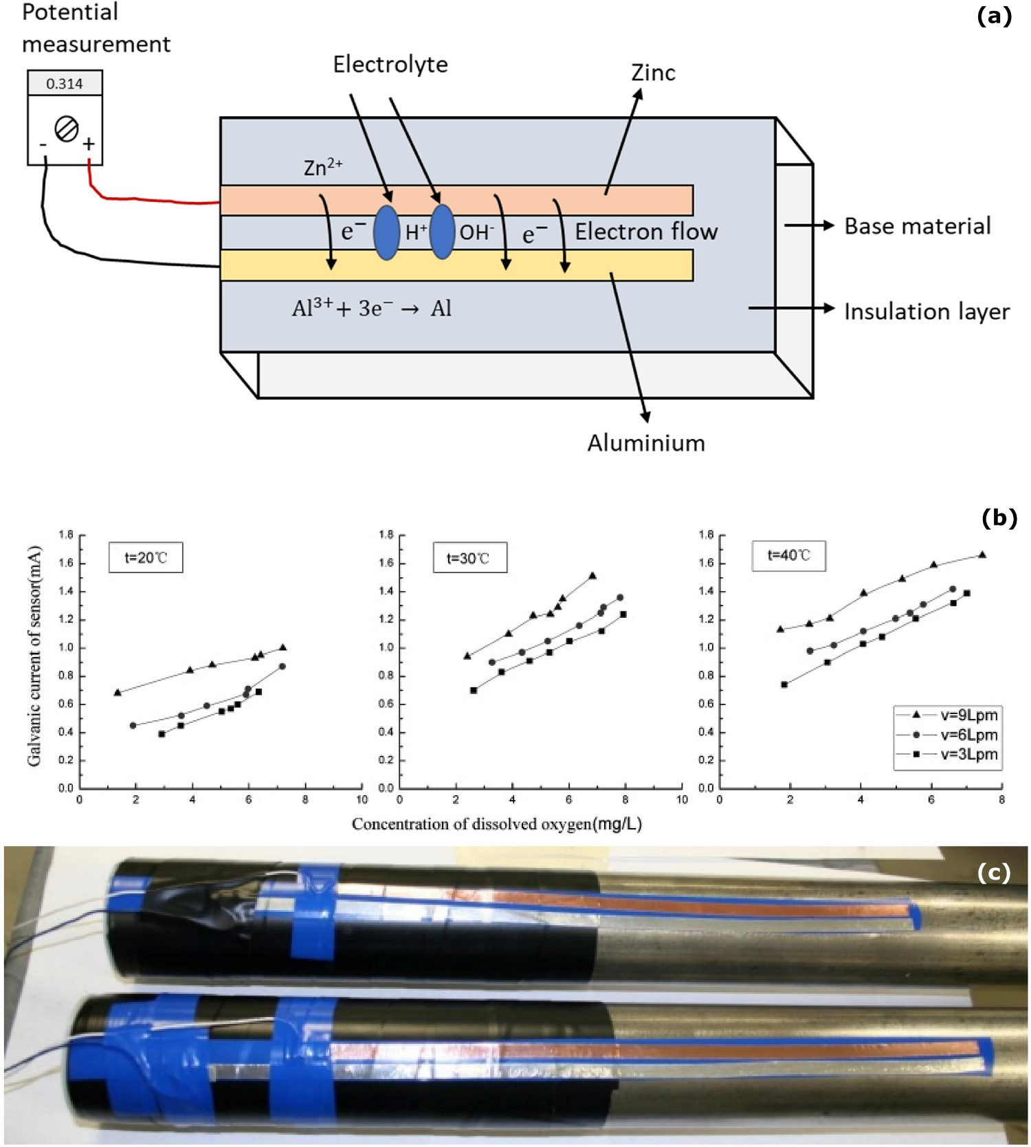
Galvanic sensor can provide continuous information on the internal pipeline conditions. Each monitoring method has their and limitations. Only one method cannot be used in all applications. In the study by Huang and Ji [12], the galvanic sensor was placed on the steel pipeline to monitor the corrosion in the sea water environment. Corrosion on the pipeline surface depends on the temperature and flow rate of the electrolyte. Figure 10b explains galvanic current increases based on the temperature and flow rate 3, 6 and 9 Lpm (litres per minute) of the electrolyte indicate the corrosion level at the interface. Galvanic sensor is a reliable tool to detect internal pipeline corrosion monitoring. Galvanic current output can also be directly related to the intrinsic aggressive potential of the environment [12].
Hill et al. [119] demonstrated the galvanic sensor concept to monitor the corrosion under insulation. A galvanic sensor is used to monitor the moisture penetration and corrosion under insulation conditions. Figure 10(c) shows the assembly of a galvanic sensor on the pipeline surface, following which the insulation layer is placed over the sensor. The insulation layer was placed on the pipeline surface to prevent a direct connection between the sensor and the pipeline surface. The direct contact between the pipeline surface and galvanic sensor leads to galvanic corrosion. The moisture penetration through the insulation layer makes the potential difference (about 500-600 mV), indicating the condition under insulation [77]. The potential difference comes to zero when the moisture dries at the interface. Developing a galvanic sensing method can be connected with the radio frequency identification (RFID) tag to indicate the moisture at the interface. In the wet condition, the galvanic sensor makes the current, and it activates the RFID tag, and the RFID tag is inactive in dry conditions. The limitation of this method is that the galvanic sensor needs to be placed on the entire pipeline length at a different angle for full monitoring of conditions. The galvanic sensor does not provide the details of identification of electrolyte and the amount of the electrolyte on the interface [77,119,120].
Galvanic sensor can also be used to monitor the reinforced steel in the carbonated concrete condition [121]. The inspection methods for the reinforced steel detect the corrosion but it does not explain the corrosion rate. The galvanic sensor can determine the corrosion rate independently. In such measurement, the working, counter and reference electrodes are embedded in the concrete. The moisture penetration, oxygen concentration and temperature changes at the interface condition make the potential difference in the galvanic sensor. The disadvantage of the method is that the galvanic current is low in high concrete resistance [13,116,121].
Electrical resistance
Electrical resistance (ER) sensor is an intrusive corrosion measurement that is designed to get metal loss data at the interface conditions, based on electrical resistance measurement. However, the sensor needs to be permanently fixed on the surface of the material to monitor corrosion [19]. Electrochemical methods such as linear polarisation resistance and impedance spectroscopy methods have been widely used to measure the corrosion rate of the structures. However, these methods cannot monitor metal loss induced by erosion. ER sensor has two areas of interest; one is corrosion element and another one is compensation element. The corrosion element is exposed directly to the corrosion surroundings. The compensation element is coated with protective coatings to segregate it from the corrosive environments. The corrosion process leads to increase electrical resistance. Based on the changes in the electrical resistance, which is directly connected to the metal loss in material thickness, it can be measured, and the slope of the metal loss curve directly corresponds to the corrosion rate [20]. ER method can be used in several environmental conditions. Moreover, it can be used in high-resistance medium and high-temperature corrosion monitoring. The metal loss is linear to the temperature of the liquid or gas flow on the structure [122]. With the advantages of the ER technique, the information is effectively used to detect corrosion in earlier stages, and it can be used in various environmental conditions, such as low relative humidity, and high temperatures. The limitation of the ER sensor is that it can measure the uniform corrosion only and cannot identify the localised corrosion. Some salts and oxides formation on the sensor provide the wrong electrical resistance which may not be related to the corrosion [12,20,66,85,123,124].
ER method can also be used to measure metal loss on the internal metal surface layer with the reaction of the electrolyte [20]. Monitoring the internal pipeline is very hard in the failure condition of the inhibition the deposit form over the bottom of the internal surface and leads to localised corrosion. The fluid flow temperature on the inner pipeline is high compared to the outer pipeline surface which leads to the condensation films on the internal pipeline surface. As shown in Figure 11a, ring pair ER sensors (RPERS) are used to monitor the internal corrosion between the pipeline and electrolyte interface. Each ring of the sensor is divided into six parts of the segments. Segment 6 is placed on the top of the pipeline and segment 3 is placed on the bottom of the pipeline. Segments 5 and 1 are symmetrically placed on the upper half of the pipeline and segments 2 and 4 are symmetrically placed on the lower half of the pipeline. 3.5% NaCl solution is used in the pipeline flow. The metal loss increases from the temperature level 30°C to 60°C and the metal loss on the six segments is not uniform, as shown in Figure 11b. The metal loss of the top layer is low compared to the bottom of the pipeline surface owing to the solution did not make a contact on the top layer. The corrosion depths of segment 3 are higher than all the segments owing to the fluid flow pressure on the bottom interface being high and accelerating the corrosion [20].
Electrical resistance (ER) method for corrosion analysis at the interface: (a) Internal pipeline corrosion monitoring system, (b) metal loss based on the temperature conditions (reproduced with permission [20] Copyright 2016, Elsevier) and (c) ER probe CUI measurement (reproduced with permission [77] by email).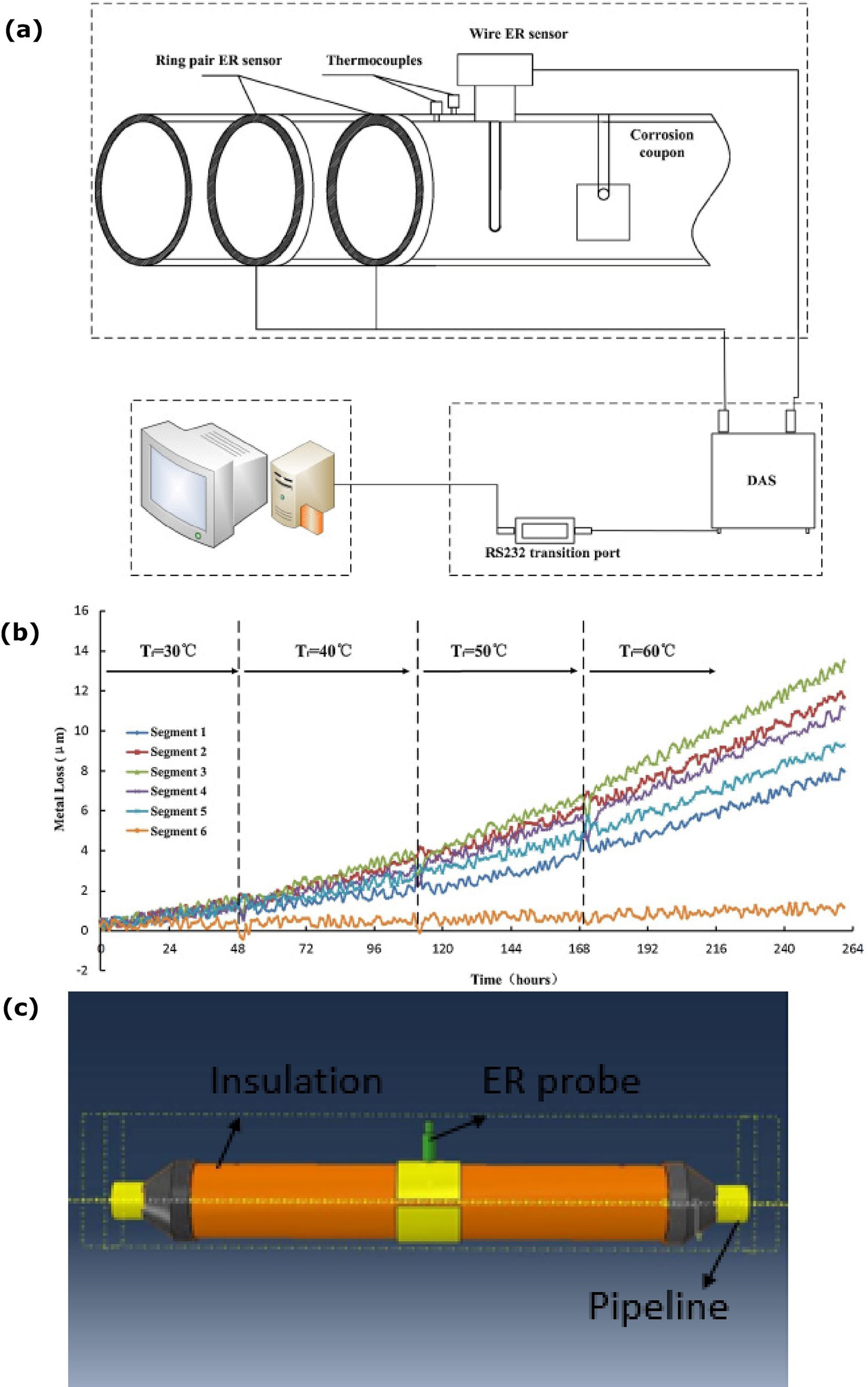
An electrical resistance probe can also be used to monitor the corrosion under the insulation, as shown in Figure 11c. The small hole is made on the insulation layer to insert ER probe to the interface condition. Wetting conditions at the interface starts the voltage difference and the dry condition voltage difference comes to zero. ER probe continuously monitors the corrosion and measure the corrosion rate. The limitation of this method is that the corrosion behaviour needs to happen in the range of the ER probe. Mostly, this method is used to monitor the corrosion with no access to the visual inspection. The disadvantages of this technique are that the ER probe may be causing geometry changes at the interface region (means increasing the corrosion) and require a high amount of ER probes to monitor the entire interface region [77,83].
ER probe can also be used to measure the general corrosion of the reinforced steel in concrete by metal loss [88,125]. In such testing, ER probe measures the corrosion damage and assessment of the general corrosion efficiently on the reinforced steel compared to the electrochemical noise method. The ER probes are embedded in the concrete slightly away from the reinforced steel interface with completely protected to the aggressive conditions. The moisture presence and corrosion at the reinforced steel interface make changes in the resistance. The quantity of the corrosion damage is measured by the voltage drop at the ER probes. Both ER probes corrode equally, while the thickness reduction on the probes indicates the corrosion [88,125].
Acoustic emission
Acoustic emission (AE) waves are owing to release of acoustic (elastic) waves, typically in the frequency range of 20 kHz–1 MHz and are generated in materials which undergo a type of deformation, dislocation movement, crack initiation or crack growth [126]. Figure 12 shows schematics and examples related to corrosion analysis using AE sensor techniques. AE can be used to monitor interface corrosion analysis (e.g. corrosion under insulation, reinforced concrete steel corrosion). AE waves mainly emerge from corrosion and cracking of the materials’ surface of sudden pressure on the material and second rise from peeling off and removing corrosion products from corroded areas [67]. A small area of the outer layer needs to be removed to place the AE sensor at the interface. For AE measurement, the corrosion or crack should be active to release the elastic waves during inactive conditions; such waves are not released from the object.
Acoustic emission technique: (a) schematic of the AE monitoring (authors original image), (b) corrosion source location (reproduced with permission [127] Copyright 2007, Elsevier), (c) types of waves (reproduced with permission [128] Copyright 2013, Elsevier), (d) Rao-Blackwellised particle filter-based signal filtering example (reproduced with permission [129] Copyright 2012, Elsevier).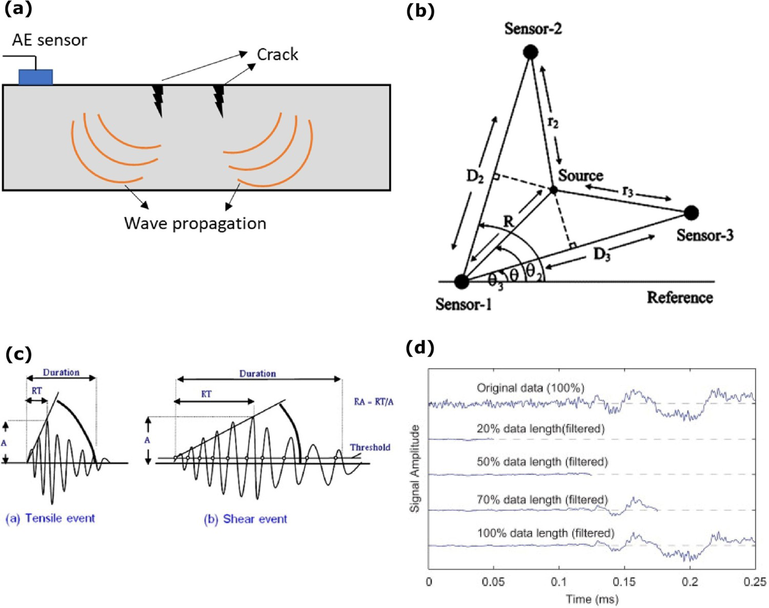
AE measurement instrument typically comes with a piezoelectric sensor, preamplifier, signal conditioning unit, connector block, data acquisition card, computer and proper software for controlling the acquisition and storage of data. All such instrumentation could be used to be assembled together as a portable device. Any crack or corrosion in the structure could release transient waves. AE sensor can measure uniform corrosion, pitting, crevice and stress corrosion cracking (SCC). AE signals from the corrosion source can be explained by various possibilities such as the evolution of hydrogen bubbles, hydrogen bubble nucleation, and damage of specimens in pitting corrosion, and analysis of the AE signals determines the corrosion location and severity of corrosion [127]. In uniform corrosion, the high number of AE counts released in the initial hours is related to the number of hydrogen bubbles generated during the process of observation. In pitting and crevice corrosion, the initial AE counts are low, and in the later stages, AE counts are increased in higher amplitude owing to the gradually destroyed passive layer of the material. In SCC, AE counts are high, spread over a wide range of amplitudes, and fell exponentially in the final stages. In the initial stages, the stress level can be high in material, and the stress level can decrease when corrosion starts. SCC is one of the most dangerous failures of the structure without any apparent warning signals. Based on the AE data, the SCC propagation is classified into two ways, i.e. tensile crack and shear crack. [11,104,130,131].
Among many advantages, the AE sensor can estimate the qualitative loss of the materials being corroded; however, it does not measure moisture level at the interface, and the AE signals can be very weak in a noisy environment as well as the discrimination of signal and noise can be challenging [132]. Noise can impair AE measurement, which can be generated for various reasons, including technological noise of the testing object and industrial operations. Various filters were designed and used to remove the noise (e.g. harmonic, and impulse noise, Wiener filter, Kalman filter, Rao-Blackwellised particle filter), and further research work is under progress to design the optimal system model and noise removal process of AE signal [129,133]. The corrosion rate of the structure can be determined through AE signals. The calculation of count per square decimetre per day (cdd) from AE signals is more like the corrosion rate determined through the weight loss method [68,134(Equation 18]):
AE technique was first used to monitor the corrosion at the reinforced steel-concrete interface in 1984 to extend the non-destructive monitoring method to detect, analyse and find the corrosion location and level of the structure damage [135]. Schematic of the AE sensor monitoring on the material, as shown in Figure 13a, Li et al. [136] assembled two AE sensors (sensor A and B) to analyse and monitor the corrosion behaviour on the reinforced steel at the interface of mortar and steel. NaCl solution (3.5%) was used to initiate the corrosion on the concrete structure and applied an external power source to make the concrete structure an anode to speed up the corrosion on the structure. Corrosion on the structure releases the energy in all the directions, and the highly sensitive AE sensors collect the data, which indicates the deformation of the material happening on the concrete structure. The AE sensor A showed a significant amount of the shear waves collection compared to the AE sensor B on the mortar (as shown in Figure 13[b]). A high number of AE wave propagates on the steel compared to mortar. The waves propagation on each material changes from the other materials and depends on their individual material component's mechanical properties. AE waves need to travel from the reinforced steel to the mortar to reach sensor B on the mortar's outer surface. It was suggested that the corrosion at the interface of reinforced steel depends on the temperature, internal moisture level and availability of oxygen. As the temperature changes, humidity at the interface strongly influences the corrosion rates. The corrosion rate of the reinforced steel changes dramatically between 80% and 90% relative humidity (RH). In this study, the AE sensor was used to study the corrosion behaviour of the interface condition, and the AE sensor was placed away from the interface [134]. Shah and Kishen [137] applied the AE sensor to study the concrete–concrete interface strength and fracture failure conditions with the sensor away from the interface of the two different concrete blocks’ connection points.
Examples from AE sensing method of corrosion at the interface: (a, b) assembly of two AE sensors to monitor the corrosion behaviour on the reinforced steel at the interface of mortar and steel and showing AE hits comparison (adapted and reproduced under the terms of the Creative Commons Attribution (CC BY) license [136] Copyright 2017, MDPI) and (c, b) assembly of two AE sensors to monitor the corrosion behaviour on pipeline structure at the interface and showing AE counts response based on moisture level (adapted and reproduced with permission [11] Copyright 2011, Springer Nature).
As shown in Figure 13c, Cho, Tamura and Matsuo [11] used AE sensors to monitor corrosion under insulation conditions on the pipeline. In this experiment, an AE sensor was placed on the pipeline surface outside the range of the insulation layer, which monitors the corrosion behaviour under insulation. Moisture was supplied at the interface of the insulation condition to initiate the corrosion reaction. The corrosion initiation released the waves, and both AE sensors were able to detect the signals. As shown in Figure 13d, the AE counts increased continuously based on the moisture leading to corrosion under insulation. The period of humidification process under insulation also accelerated the corrosion. AE waves propagated from the under-insulation interface through the pipeline to the AE sensor. With distance, the wave energy diffuses in all directions. However, AE sensors can accumulate the low number of AE waves and can still provide a signature associated with corrosion. In such measurements, keeping the AE sensor distant away from the interface does not always provide the exact corrosion condition of the interface [11].
AE sensor can also be used to monitor the interface corrosion and leakages on large structures such as vessels and the bottom part of a storage tank. Specialised AE sensors (e.g. low-frequency sensors can be used to monitor corrosion at the interface of storage tanks owing to low noise levels in such storage facilities [134]). In such measurements, the AE sensor can be placed on the surface of the storage tank wall, where waves can travel from the bottom of the tank to the sensor through the liquid medium on the storage tank or storage tank wall. However, a detailed study is needed to differentiate the source from the corrosion or noise from the interface environment in such large storage structures. Placing the sensor at the interface and enhancing the sensor data collection sensitivity could help to monitor the tank (bottom part) interface conditions effectively. AE sensors can also monitor the corrosion on pipeline supports interface but needs further investigation to correctly identify AE source from the corrosion or external pressure or other reasons [67,134].
Optical fibre humidity sensor
The presence of moisture at the interface or object surface initiates the corrosion. Continuous monitoring is a key option to keep the object and the operating environmental conditions safe. Optical fibre humidity sensor is a technique that can help monitor the large structures with distributed sensing applications [138,139]. Deployment of such sensing can be an appropriate approach to monitor moisture ingress and presence at the interface [69]. In such measurement, the optical fibre core is assembled near the interface (but not exactly on the pipeline surface) of the pipeline surface and thermal insulation, as illustrated in Figure 14a. The laser light source travels through optical fibre covered with a hydrophilic polymer layer. Hydrophilic polymer layer reflective index changes when it absorbs moisture. Normally a sensitive coating layer can be used to increase the sensitivity at various temperature conditions. At another end of the optical fibre, photodiode measures the transmitted laser power travel through polymer and sensitivity coating. The laser intensity increases at higher-level moisture conditions. The relative humidity (RH) level changes optical density (from 60% to 80% RH range, the laser power increases, and after 90% RH, the laser power decreases). Coatings with 5 wt-% CoCl2 and 5 wt-% polyvinyl alcohol (PVA) on the sensor and connecting to another sensor coated with 5% pullulan (a natural polysaccharide) to extend the measurement range of the sensor. With such innovative methods, sensor can measure the moisture up to 95% RH, as shown in Figure 14b [11].
Examples from optical fibre optic sensing method of corrosion at the interface: (a) assembly to monitor the humidity at the interface of corrosion under insulation on pipeline structure (authors original image), (b) showing optical intensity response based on relative humidity (adapted and reproduced with permission [11] Copyright 2011, Springer Nature) and (c) di – ureasil coated optical fibre embedded concrete structure measuring the relative humidity of the concrete (adapted and reproduced under the terms of the Creative Commons Attribution license [140] Copyright 2012, MDPI).
Optical fibre humidity sensor has several advantages such as miniature design, durability, appropriateness for higher temperature, pressure conditions and it can observe higher humidity at high temperature (about 60°C–80°C) under insulation conditions. The disadvantage is sensitivity issues at higher temperatures [11,138]. Temperature changes at the interface affect the optical fibre refractive index strains. In practical applications, the humidity sensor is influenced by the temperature changes strain at the interface and indicates wrong moisture response. To overcome such a challenge, Thomas and Hellevang [69] invented the sensing cable that includes humidity sensor and temperature reference fibre. This technology can measure the water level less than 10 ml at the interface and can differentiate the strain responses from the relative humidity and temperature.
Moisture measurement at the concrete-concrete blocks interface can be carried out using various methods such as sensing the capacitance, resistive and relative humidity (RH). However, such sensors have the disadvantages of high cost, inability to use at hazardous location or explosive in natural environments required high maintenance. The optical fibre sensor can overcome those disadvantages and sense the pH, moisture, temperature and pressure levels. Polymer, polyimide and different coatings can be applied on the optical fibre to enhance mechanical strength and sensitivity. Kronenberg et al. [141] studied the polyimide coating on the optical fibre sensor sensitivity to RH on the temperature changes. The organic silica hybrid material can provide high sensitivity and durability.
Referring to a work by Correia et al. [140], Figure 14c illustrates an assembly of organo-silica hybrid material (named as di-ureasil, which function as photoactive component) coated optical fibre embedded in the centre of the concrete structure to measure the relative humidity of the concrete surface and shows relative humidity changes based on the concrete structure porosity. Here, the holes can be sealed with epoxy resin to prevent moisture penetration. This study confirmed high relative humidity with high concrete structural porosity throughout the year of study. The di-ureasil coated optical fibre showed enhanced stability, sensitivity, adhesion and compatibility compared to the siliceous-based network [140].
Thermocouple sensor
Thermocouple is the most popular sensor to measure the temperature because of its robustness, ease to manufacture and installation, and low cost [142]. Such sensors are composed of different metal combinations at their sensing end. Owing to temperature gradient between hot sensor element and cold reference junction, a voltage is formed, and any difference in voltage is reported as temperature through the Seebeck effect [14]. The measurable temperature range could be from −270°C to 2300°C [14,70], and it could measure temperature rise of solid structures, pipeline and interface conditions [142,144]. Thermocouple sensors are typically placed on the object's surface at the interface to measure temperature. The temperature fluctuations could initiate corrosion and could be directly related to corrosion rate. The thermocouple sensor is easily susceptible to the corrosion presence of moisture and temperature fluctuations. At the interface applications, thermocouple sensor can be coated with Teflon to prevent its corrosion. It can measure the temperature range 0°C–80°C with high-level of accuracy. The disadvantages of thermocouples are that it is less accurate than platinum resistance temperature detectors, and protection are required to stop the contamination for long life service [14,20].
CUI majorly depends on the temperature at the interface condition. Water transmits from the cold/hot outside exterior to the hot/cold pipeline surface owing to insulation defects and improper insulation installation. In stainless steel, low-temperature conditions do not provide an actual passive layer on the metal with continuous, non-porous and self-protection against corrosion. Cyclic temperature decreases the strength of the protective coating and insulation. Monitoring the temperature at the interface is vital to predicting the corrosion on the interface. The thermocouple sensor is typically placed at the interface between the heat plate and insulation in such experiments. Various thickness (5, 2.5 and 1 cm) of the insulation was used and measured the water penetration and temperature change at the interface. The water penetration time increases linearly with the insulation thickness to reach the interface of the heat plate and insulation, which takes a long time to make a change in the interface temperature. The limitation of this method is that placement of the sensor in a particular location helps monitoring the temperature at that location only, means not representing other locations. Also, the sensor placement a little away from the plate means that it does not indicate the exact temperature [69,78,115,145].
Monitoring the temperature of concrete gives an important information of hardening of concrete, carbonation, alkali-aggregate reaction, reinforced steel degradation on concrete. Various types of sensors are used to monitor the temperature of concrete such as micro electrochemical systems (MEMSs), optical fibre sensors, infrared photography, radio frequency identification (RFID) sensor and thermocouples. The high and low-temperature conditions badly affect the concrete and reduce the strength and lifetime of the concrete. The sudden internal temperature change leads to the concrete cracking and accelerates the reinforced steel corrosion. The hydration on the concrete increases the temperature which transfers non-uniformly on the concrete initiates premature failure. To carry measurements, temperature sensor is typically embedded in the concrete as close possible to the reinforced steel to monitor the temperature. Concrete temperature measurement can be influenced by different humidity conditions. Recently, wireless communication sensors have been used to monitor temperature. However, the limitation of this method is that such electronic components need to be placed on the concrete and its continuity, stability of signal transmission and ability to withstand the harsh environments can be uncertain [146 148].
pH sensor
pH sensor is typically used to measure the amount of acidity or alkalinity in water or other solutions [79]. Such sensor measures the voltage between the two electrodes. It converts the result into the corresponding pH value, which are wildly considered for various applications such as food processing, health monitoring, water quality monitoring, nuclear and agriculture sectors with various operating mechanisms [149].
Most concrete structure failures happen owing to a decrease in the pH (i.e. alkalinity). The fresh concrete typically has a pH value of around 13, forming the passive layer on the steel. pH sensor can be used at the interface of the reinforced concrete to monitor the pH based on the chloride ions changes and the carbonisation process of concrete. The pH sensor is typically placed close to the steel and the reference electrode. The carbonisation process could destroy the passive layer of steel and reduce the pH of the reinforced concrete, measured by the pH sensor. The chloride ions drop makes a significant impact on the pH value of the concrete. The chloride ions become close to zero, which drops the pH value to 11 and initiates the active corrosion of the steel [15,79,149 151]. The pH sensor has the advantages of long-term measurements, high sensitivity, fast response time, low cost and good mechanical stability.
Gao and Song, [71] developed the pH sensor with a novel electrochemical measurement system to measure the pH at the interface of sensor and solution. The working, reference and counter electrodes terminals were connected to the potentiostat and placed in the electrolyte, applied external potential on the sensor which resulted in current changes based on the electrolyte pH. Various types of pH sensors have been developed to achieve high sensitivity. Pencil graphite electrode coated with the polyaniline (PANI) film connected series to working and counter electrode. This can help to avoid current flow in electrolyte and makes it through the series electrode. The current varies with changes in the solution pH. The current changes directly reflect the pH value at the interface, as shown in Figure 15a,b. PANI film offers high sensitivity, stability and accuracy.
pH sensor for corrosion anlaysis at the interface: (a) current and potential for various pH values, (b) current vs. pH (reproduced with permission [71] Copyright 2009, Wiley), (c) sensor stability (reproduced with permission [72] Copyright 2014, Elsevier) and (d) pH sensor response (reproduced with permission [79] Copyright 2016, Elsevier).
Various sensors are used to measure the pH of the steel bar and mortar interface based on various conditions. The interface pH value is the key reason for the reinforced steel lift time. The pH value above 10 keeps reinforced steel passivated and minimises corrosion. An optical fibre pH sensor has been developed recently to measure the pH 10-13 range in the concrete structure with good stability, shown in Figure 15c [72]. It is an active method, and, in such measurement, the fibre optic is placed close to the interface. The concrete pH level is between 12.5 and 13.5 in the new condition and starts to decrease to 9.5 owing to the carbonation process on the concrete structure [79]. Monitoring the pH range 10-13 is important for the corrosion prediction at the interface and for the concrete structure safety. The pH measurement is associated with the inconvenience of electrode failure, low sensitivity and ambiguity. Also, to overcome the challenges of sensor long stability in the alkaline conditions, sustaining the harsh working conditions and sensing the pH value of concrete at immediate contact point with the concrete is necessary. Also, optical fibre sensor design with polymer and nylon membrane to provide strong mechanical strength and which can withstand the harsh corrosive interface environment can be considered [72].
The pH values can be measured in concrete structure through the fibre optic pH sensor. Fluorescence light emitted from the sensing element passes through other branch of the optical fibre, and the output pH value shows up in the computer display [72,152]. As shown in Figure 15d, the sensor stability is strong at the interface condition for an extended period. Embedded potentiometric electrodes, solid-state pH sensors, hydrogel films and fibre optic sensors are different sensor types that can be used to monitor the pH values [79]. Metal electrodes are suitable for use in concrete owing to their stability, robustness and flexibility. Iridium metal electrode is more developed than other metal electrodes. In such measurement, the metal electrode can be placed close to the steel bar in the concrete.
Chloride sensor
Chloride ions present on the electrolyte or concrete results in chloride corrosion on steel. Localised chloride-induced corrosion on the reinforced steel leads to severe structure failure and makes expensive repair work. The best option to minimise chloride corrosion is the prevention of chloride ions and monitoring the chloride ions changes in the concrete structures. Chloride sensor works on the principle of measuring potential between working and reference electrode. Earlier destructive and time-consuming processes were used to assess the chloride in the concrete. Recently, the new development of sensors provides continuous monitoring of embedded probes on the concentrate [16,153].
Recently, Cao et al. [154] discussed the significance of chloride ions on CUI. It was suggested that some of the insulation materials contains chloride ions themselves which should not be above threshold level on stainless steel applications. The corrosion products of steel highly depend on chloride level, the α-FeOOH and ion oxides are dominant on low chloride level and γ-FeOOH and β-Fe8O8(OH)8Cl1.35 are high found on high chloride level. Additionally, on the ingress of saltwater, electrolyte evaporation on a high temperature operational condition leads to the chloride concentration increases and coating delamination. High-resistant protective coating (i.e. aluminium coating) can be possible to mitigate the coating degradation and corrosion. More suitable sensor placement at the interface of insulation and base material will be helpful to monitor the chloride ion activity effectively.
Montemor et al. [16] prepared the multi-probe chloride sensor with silver and copper wires, as shown in Figure 16a and embedded it in the mortar. A 0.5 M NaCl solution was stored above the sensor-embedded mortar to find the chloride ions penetration with used saturated calomel electrode (SCE) as a reference. As shown in Figure 16b, the potential decreased with the chloride ions diffuse on the mortar with respect to time. 1 cm probe shows sudden decay on the potential owing to which is closer to the surface. Based on time increase, the other sensor probes have the potential drop, which indicates the chloride penetration on mortar. The diffusion of chloride ions based on the depth is shown in Figure 16c. Angst et al. [155] studied the chloride penetration on several concentrate mixes such as portland cement (PC) and sulphate resistant (SR) with the combination of fly ash (FA). For the chloride monitoring purpose, the six chloride and resistivity sensors and manganese dioxide reference electrode are placed in the samples holes which are made in concrete block preparation time with round Teflon bar. SCE is used manually to measure the potential. These sensors contain the chloride ion selective electrodes (ISE) which monitors resistivity of the concrete. Chloride ions increase in concrete, drops the resistivity of the concrete which enhances the electrical conductivity and corrosion reactions. The samples are exposed to the chloride solution for 1 week wetting and drying cycles for more than 1 year. For the first 42 days, all the sample potentials are from −150 to −70 mV with respect to the SCE and passive layer formation on the during this period (Figure 16[d]). The potential is decreased with sample exposure time increased on the chloride solution clearly indicates the depassivation and passivation process with chloride concentration. The concrete block resistivity linearly decreased with the faster increased on the chloride concentration penetration. Chloride ions activity continuously monitored with ISEs, chloride contents on concrete block changes with composites of concrete.
(a) preparation of chloride sensor, (b) potential reading based on the 0.5 M NaCl penetration, (c) chloride ions diffusion indication with sensor depth (reproduced with permission [16] Copyright 2006, Elsevier), (d) potential measure of concrete samples (reproduced with permission [155] Copyright 2011, Elsevier), (e) electrode potential (mV) vs. chloride activity (reproduced with permission [156] Copyright 2016, Elsevier).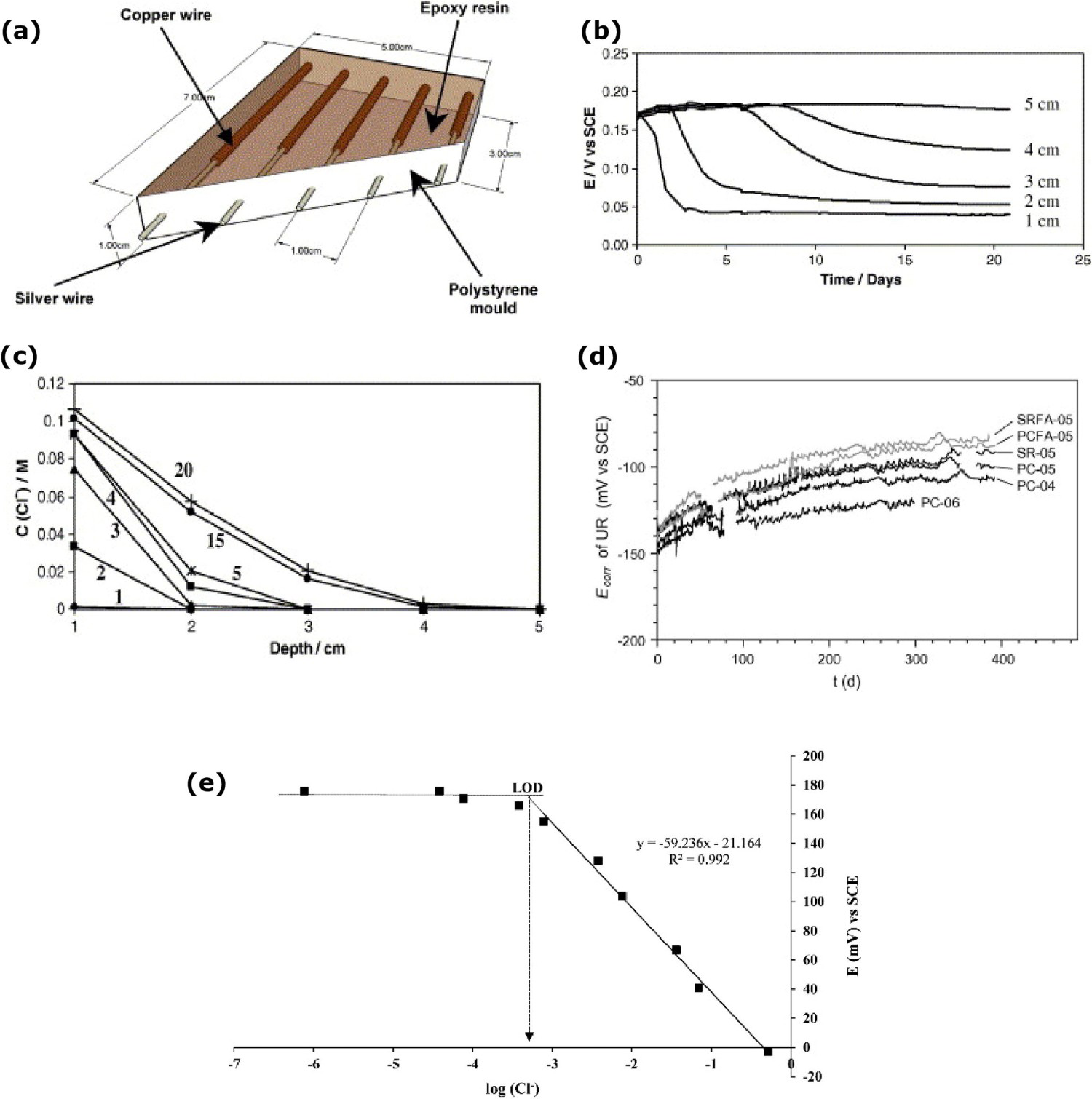
Gardia-Romero et al. [156] investigated the new approach of thick film chloride sensor (TFCS) to monitor the chloride penetration process. Previous studies suggested the embedded sensors on the concrete to obtain the immediate chloride properties changes of the concrete and it has the limitations of short service life and damaged in hardest environmental conditions. To overcome such disadvantages, the thick film sensors are pasted on the concrete block with conductive paste (Ag/Pd). Figure 16e shows the representation of average sensor potential measurement with respect to the chloride contents. The initial slope depends on the pH value and second Nernstian region depends on the chloride ions with high level of reliability. Advantages of sensor shows the quick response time and chloride ions sensitivity close to 59 mV/decade.
Special consideration for sensing materials and monitoring methods
As seen from aforementioned examples, the sensor and sensing methods play an important role and can help achieve assessing corrosion conditions at the interface of structures. This section provides an overview about some direct considerations warranted which can further enhance interface corrosion analysis (including quantifying moisture, chemical species, temperature, pH, gases and other changes or degradations) by using advanced materials, developing specialised sensors through those materials and their design. The selection of suitable sensor materials, their design and assembly require understanding of the measurement needs, behaviour, and properties to be measured, and overall interface corrosion monitoring requirements. Advanced or smart materials can detect certain environmental condition changes efficiently. The details provided here are not exhaustive, but such materials contain multifunctional properties such as exceptional chemical, electrical, mechanical and thermal, and such materials could be used to build smart structures such as sensor network and actuators [157,158], and potentially complement the existing sensor and sensing methods.
Indium tin oxide
Indium tin oxide (ITO) thin films can be deposited over the substrate using various deposition methods such as chemical vapour deposition, pulsed laser deposition, spray pyrolysis, sputtering and sol–gel spin coating method. Among these methods, the sol–gel spin coating method makes a great influence on the film properties by modifying the size and structure of the inorganic substrate [159]. ITO have been used as electrodes in solar, humidity and gas sensors owing to its properties such as low electrical resistivity, and optical transparency in the visible light region. Generally, the optical energy gap is high (about 3.3-4.3 eV) when the ITO deposition process is carried at low temperature [160]. However, annealing at high temperatures (leading to enhanced crystallinity) can decrease the optical energy gap, potentially increasing the sensitivity to humidity levels. As annealing temperature increases from 300°C to 600°C, the optical energy gap decreases from 3.85 to 3.23 eV [161]. The resistance of ITO thin film decreases when the relative humidity (RH) increases because of water molecules which donates the electrons to the thin films. Owing to small energy gap and improved crystallinity, the humidity sensor can have high sensitivity and fast response time. As shown in Figure 17a,b, the average response and recovery time are 68 and 54 s at 300°C temperature. At 600°C, the average response time and recovery time decreased to 28 and 14 s, respectively [159]. ITO crystalline structure is shown in Figure 17c [162].
Indium tin oxide (ITO): (a) Response and recovery time of ITO variation with annealing temperature, (b) sensitivity of ITO films against relative humidity (reproduced with permission [161] Copyright 2017, Springer Nature) and (c) crystalline structure of ITO (reproduced with permission [162] Copyright 2020, Springer Nature).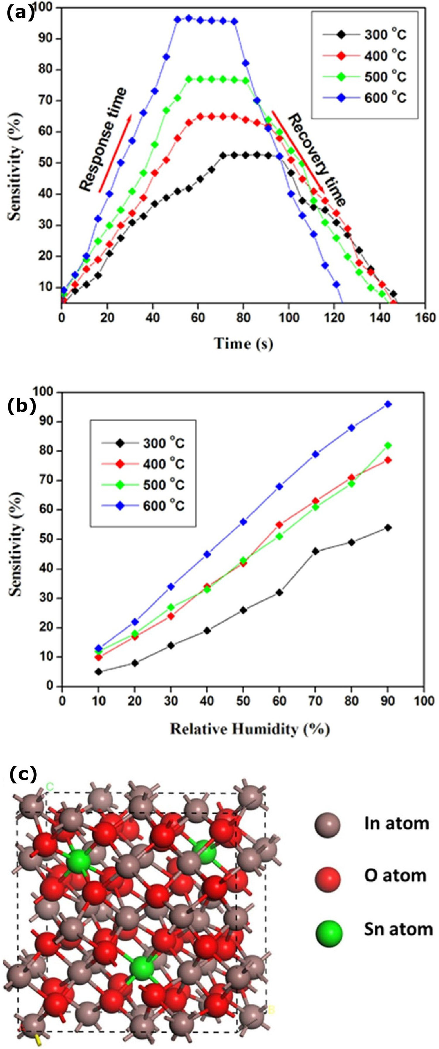
Humidity level sensitivity characteristics of ITO thin films can help in monitoring moisture at the interface conditions. Premkumar and Vadivel [161] analysed the sensitivity of the ITO thin films at different annealing temperatures. ITO thin films (deposited on glass substrate by selected deposition methods with appropriate thickness, In:Sn concentration, substrate and annealing temperature) could greatly influence such film to have an effective low resistivity and high humidity sensing response. For the future design of ITO as a humidity sensor, the parallel set-up of two ITO coated glass plates can be designed to keep at the interface region, and moisture at the interface of plates could make resistance/capacitance change. The high band gap, simple film fabrication, quick response and recovery time are some of the advantages of ITO thin film which could be considered for interface humidity monitoring.
Zinc oxide
Zinc oxide (ZnO) is a multifunctional material because of its unique physical and chemical properties such as high chemical stability, high electrochemical coupling coefficient, radiation absorption and high photostability [163]. ZnO can be produced using various methods such as vapour deposition, precipitation in water solution, hydrothermal synthesis, sol–gel process and mechanochemical process, making products with different shapes, sizes and spatial structures. ZnO can be deposited on various substrate types including paper-like substrate [164]. Since ZnO deposition on glass or silicon substrate cracks under mechanical stress, therefore substrates with plastic deformation behaviour are more suitable for humidity sensors. The critical electrical properties of ZnO are that its resistance can be reduced with an increase in humidity owing to the adsorption of hydrogen molecules [164]. ZnO has effective characteristics of moisture sensors, including high sensitivity, fast response time, chemical stability and low cost. As shown in Figure 18a, the resistance is low compared to bulk materials and decreases based on relative humidity increases. Figure 18b,c shows schematic diagram of the ZnO nanomaterials humidity sensor and an example image of ZnO nanoparticles. The annealing process above 550°C enhances the response time, long-term stability and humidity sensitivity of ZnO [163,165,167].
Zinc oxide (ZnO): (a) Resistance variation based on humidity (reproduced with permission [164] Copyright 2012, Elsevier) and (b) nanomaterials humidity sensor (reproduced with permission [165] Copyright 2005, Elsevier), (c) SEM image of ZnO nanoparticles (reproduced under the terms of the Creative Commons CC – BY license [166] Copyright 2020, Elsevier).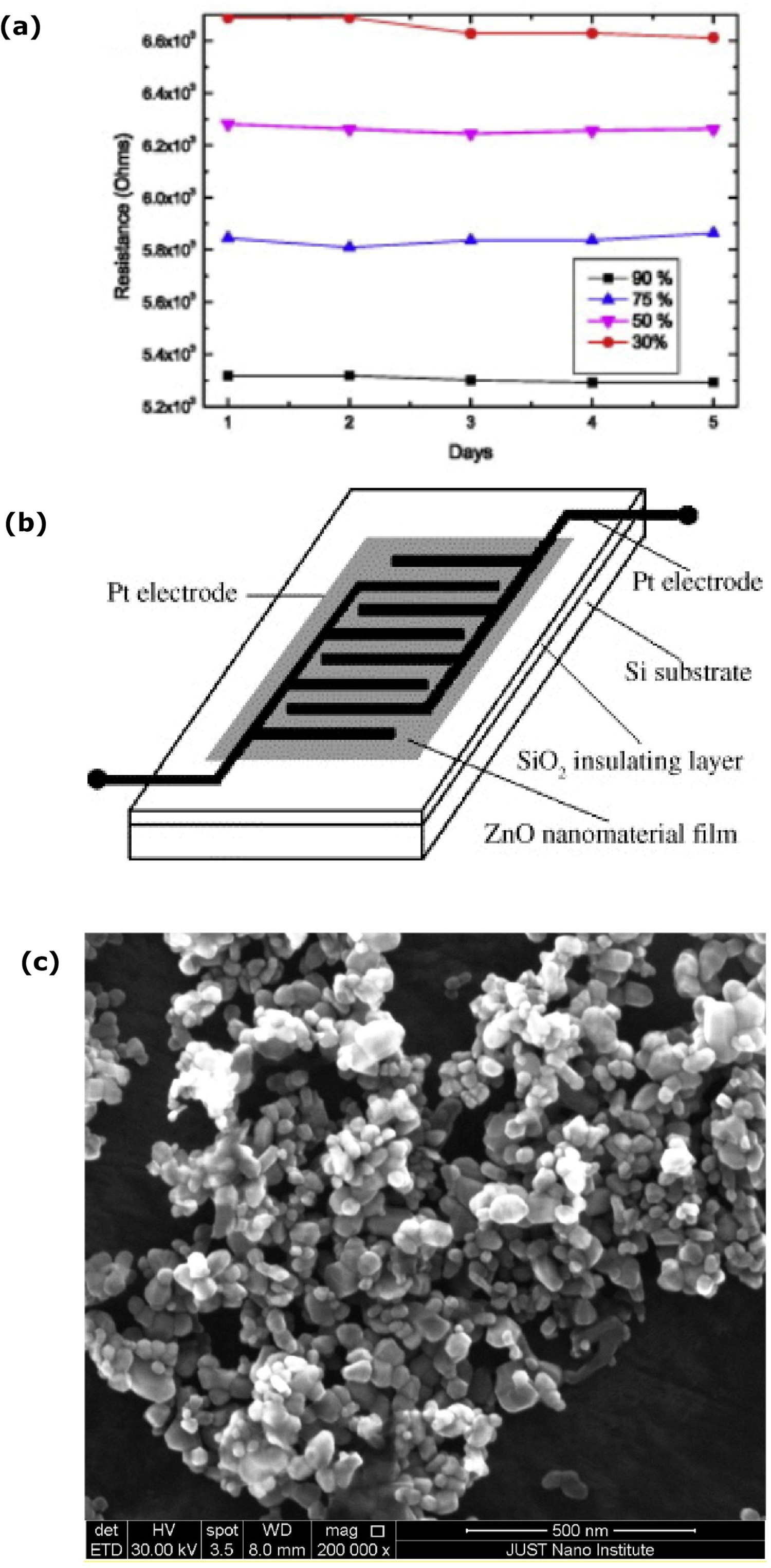
Through various examples, it has been shown that ZnO-coated substrate detects and monitors moisture on the substrate surface. Such coating can be stable and consistent for the long service, and advanced ZnO thin film (in the form of nanomaterials) coated substrate placement at the interface can detect the moisture quickly with its high sensitivity characteristics. Also, the long-term chemical stability, high thermal and mechanical stability at room temperature characteristics could extend the interface moisture monitoring of ZnO thin film (nanomaterial) without the requirement of high maintenance [164,165]. A layer deposition of metal oxide on ZnO enhances the humidity absorption and improves the response and recovery time performance [168]. Therefore, combination of properties and characteristics of ZnO could be helpful for interface humidity monitoring.
Zirconium dioxide
Zirconium dioxide (ZrO2) (Zirconia) is used as oxygen and humidity sensor [169,170]. The properties of ZrO2 strongly depend on its microstructure such as shape, size and crystal phase. Oxygen sensors are used in chimneys, cars and air transport to control the fuel to air suction ratio, enhance the fuel combustion process and minimise the toxic substance released into the environment. ZrO2 is an important oxygen sensor and a remarkable component of catalysts used in fume purification. Stable at high-temperature operating conditions, high chemical resistance and excellent mechanical properties are advantages of ZrO2. The mechanism of bifunctional properties enables the surface to be used in acid–base catalysts. Based on the temperature conditions, ZrO2 has three crystallographic forms. Monoclinic form up to 1200°C, tetragonal form between the temperature range of 1200°C to 1900°C, the regular structure over 1900°C to the melting point at 2670°C [171]. ZrO2 oxygen sensor can be placed in the gas mixture. An electrode can absorb the oxygen and various reactions can happen. The reaction affects the oxygen adatom (i.e. an atom that lies on a crystal surface) concentration of the sensor, which changes oxygen concentration inside the solid electrolyte. The current density changes between the very close electrodes and the electronic charge on the electrodes give an electromotive force rise with respect to inverse redox ratio R′ = (2PO2/PH2) on the observed sensor, as shown in Figure 19a [169]. Figure 19b shows an example of ZrO2 image [172]. Multilayer nanostructured (titanium dioxide) TiO2/ZrO2 thin film measured the humidity from 11% to 97% RH with 54 and 126 s of response and recovery time [173]. Recently, Sathya [174] designed the humidity sensor thin film of aluminium oxide (Al2O3) on the ZrO2 and measured the humidity from 10% to 90% RH with an average sensitivity of 2.226.
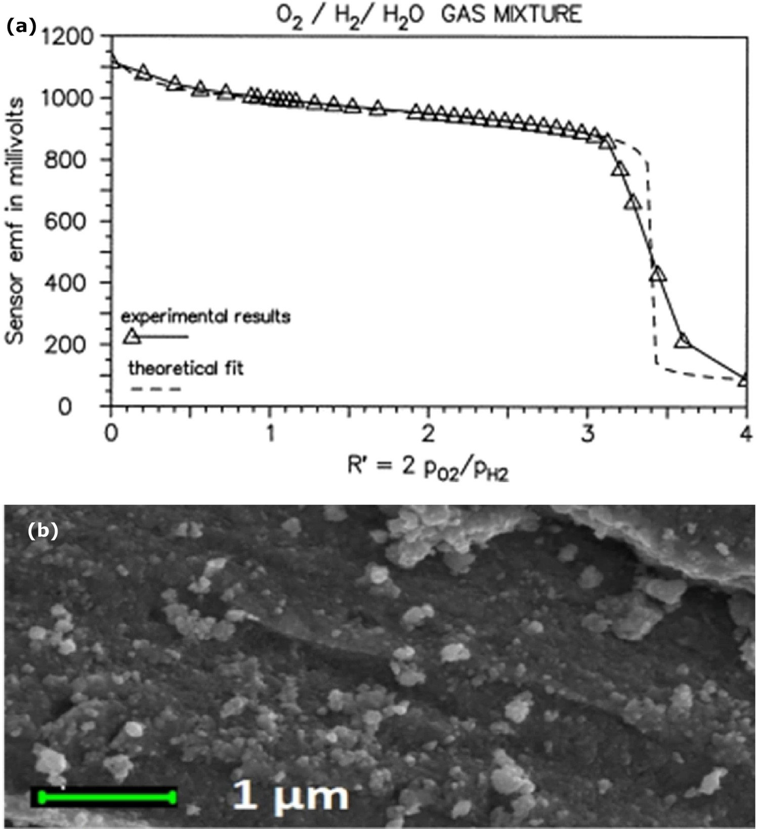
High chemical resistance, high-temperature operations and outstanding mechanical properties of ZrO2 are the main reason for its usage as humidity, oxygen sensor in combustion engines and other applications. Zirconia sensor placement at the interface can detect airflow and humidity and work effectively in high-temperature conditions [171]. Some of the interface working conditions are at high temperatures and finding smart materials with high-temperature stability is vital to enhance the interface condition monitoring. High stability at the higher temperature range of ZrO2 is the advantage of applying the ZrO2-based sensor at the high-temperature interface medium. ZrO2 sensor performance ability is enhanced through the design in combination with other metal oxides. Therefore, combination of properties and characteristics of ZrO2 could be helpful for interface humidity and oxygen monitoring at high temperature interface conditions.
Lead zirconate titanate
Structural health monitoring (SHM) is a method to monitor structural conditions through embedded innovative materials sensors. Lead Zirconate Titanate (PZT) or (Pb[Zr(x)Ti(1−x)]O3, where 0 ≤ x ≤ 1) ceramic is one of the most used piezoelectric materials. PZT has a high level of sensitivity compared to polyvinylidene fluoride (PVDF) [175]. The dielectric and piezoelectric properties of PZT are based on the intrinsic (lattice distortion), extrinsic (i.e. domain, phase wall motion and polarisation rotation) mechanisms and temperature. The piezoelectric properties are linear at a temperature range from 0°C to 50°C, and at a low-temperature level, the mobility of the domain walls is reduced [176]. A PZT transducer is shown in Figure 20. The efficiency of the PZT transducer increases with the temperature rise. In a perovskite structure, PZT has ferroelectric properties. The low temperature and impurities on the PZT reduce the electrical conductivity of the ceramics. This conductivity reduction directly impacts the power loss of the system [178 180]. In AE system, the transducer senses the elastic waves on the structure induced through mechanical stress or failure. The advanced flexible AE sensor is based on the PZT nanofibers with a diameter range from 50 to 120 nm, and it is advantageous for small size, high flexibility, high sensitivity and low cost [175,181].
Lead Zirconate Titanate (PZT) removable transducer (reproduced under the terms of the Creative Commons attribution (CC-By) license [177] Copyright 2020, MDPI).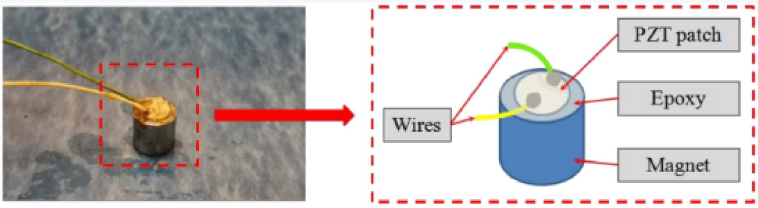
Through various examples, it has been shown that the piezoelectrical properties of the PZT helps to monitor the mechanical stress release owing to degradation or fracture in material [175]. Small size PZT transducer placement at the interface can detect the mechanical stress released from the gradual degradation or failure of the materials effectively. High sensitivity of PZT can improve wave collection efficiency and can detect a minimal level of changes at the interface.
Carbon nanotube
Carbon nanotubes (CNT) are tubular structures with large length/diameter ratio [182]. Nanotubes are one-dimensional structure that can have impressive mechanical and electrical properties, thermal conductivity and structural stability. Nanotubes are metallic or semiconducting based on structural parameters requirement and it has high Young's modulus and tensile strength [182,183]. Carbon nanotubes are very sensitive to the chemical environment [184]. As shown in Figure 21a,b, single-walled carbon nanotubes (SWCNTs) and multi-walled carbon nanotubes (MWCNTs) are fabricated mainly by three methods, namely arc-discharge, laser-ablation and catalytic growth. SWCNTs structure growth is controlled by the nucleation step. C–C bonds are very strong, and it is difficult to break and reform the structure [182,187]. SWCNTs elastic modulus, tensile strength and Poisson ratio is 0.764 TPa, 6.249 GPa and 0.32, respectively, which are low compared to graphite [188]. The electrical resistance decreases with decrease in temperature. For example, at 300 K electrical resistance is around 30 kΩ, and at 50 K electrical resistance is around 16.5 kΩ [189]. MWCNTs are very complex than SWCNTs. Through chemical vapour deposition MWCNTs can be built with varying diameter of 20-40 nm and 1-50 µm in length. MWCNTs have high tensile strength properties and the outer carbon tubes cannot provide shield to inner carbon tubes from chemical substances [185,190].
Carbon nanotubes (CNT): (a,b) Single and multiwalled carbon nanotubes (reproduced with permission [185] Copyright 2020, Elsevier) and (c) CNT array of aluminium template and (d) response to H2 exposure as the relative change in device resistance (reproduced with permission [186] Copyright 2008, Wiley).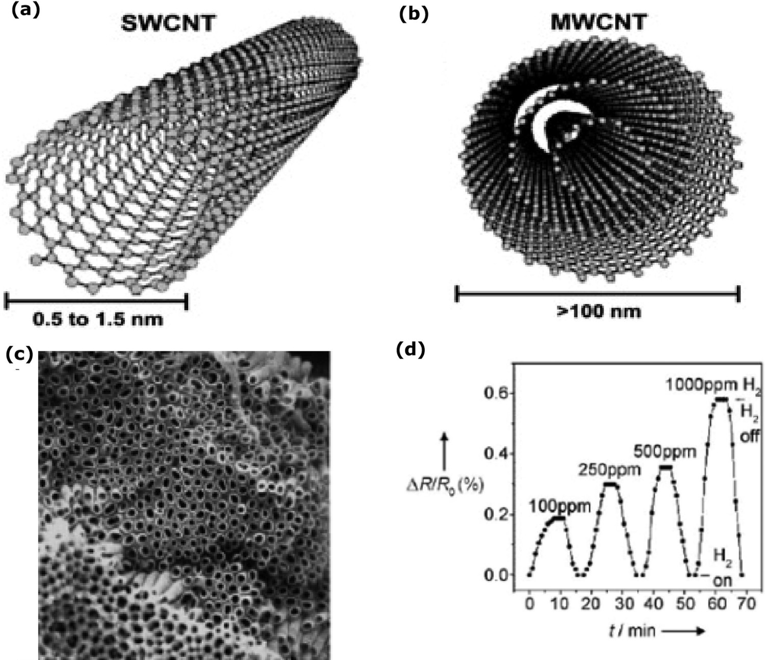
CNTs have various applications, such as additives to polymers and catalysts, sensors, supercapacitors, lithium batteries, energy conversion cost-effectively [191]. The mechanism of CNTs make a great influence on the mechanical, electrical, magnetic properties of the overall network. High gas sensitivity properties of CNTs provide an opportunity to develop highly sensitive super miniaturised chemical and biological sensors [191]. The main operating principle of the CNT gas sensor is that the gas molecule transfers the electron to the CNT which influences CNT's electrical properties. CNT monolayer gas sensor is very sensitive to NO2 which makes the direct conductivity changes of the CNT. Initially, NH3 and H2 show zero binding affinity with CNTs. Various methods are used to improve the sensitivity and selectivity of CNTs sensors. High sensitivity of NH3 achieved through building the inner wall with alumina templates and CNTs made with aluminium template top coated with Pd show a high sensitivity of H2, shown in Figure 21c,d. At low-temperature conditions, H2 gas sensor sensitivity improves through added H2 adsorption modifier [186,192]. The advantages of CNT gas sensors can reduce the risk of combustible gases through detect the combustible gases effectively. The temperature fluctuations in the environment do not influence the sensitivity of the sensor. The CNT sensors have high sensitivity and selectivity, response and recovery time [191,193].
Carbon nanotubes have high mechanical, electrical properties, stability and thermal conductivity [182]. There are numerous examples where gas and electrochemical sensors are fabricated using CNT's. It has been demonstrated that the high sensitivity behaviour of CNT's enhances efficiency of the chemical and biological sensors [191]. Also, an excellent thermal stability of CNT shown at 700°C for an extended period [194] can be one of the main advantages of using CNT's for interface monitoring. It is expected that CNT-based sensor placement at the interface can effectively detect and monitor gas presence (owing to some electrochemical reactions depending on the type of outer layer) near the interface region.
Nanowires
Nanowire is typically a cylindrical nanostructure with diameter about less than a nanometre [195]. Nanowire is highly versatile and has excellent electron-transport properties along with good biosensing properties and the charge carrier motions can be enhanced by nanowires compared to their bulk counterpart, which is used for electrical, ultrasensitive sensors and find a failure/susceptibility area in the chemical and biological field. Based on the studies, nanowire-based sensors show improved performance [196,197]. Nanowires can be fabricated in two ways, namely bottom-up fabrication such as vapour liquid–solid (VLS), metal–organic decomposition, molecular beam epitaxy or top-down fabrication such as electron beam lithography, ion beam etching, thermal evaporation oxide-assisted growth (OAG), metal-assisted chemical etching (MACE) [198].
Nanostructured materials in the form of nanowires and nanoparticles have already made a significant breakthrough in various field, including the biomedical sensing applications. High sensitivity of biomedical sensors detects diseases at the earlier stage and increases the chance of lifesaving. The surface area to volume ratio is vast at the nanoscale, which influences most areas on the sensing structure, preparing a nanostructure ultrasensitive to changes on its surface [199]. The sensitivity in high ionic strength solvent and long-term stability of the nanowire will make an incredible impact for interface sensing and monitoring.
Copper nanowire
Single and polycrystal copper nanowires (Cu NWs) can be fabricated using methods such as chemical vapour deposition, vacuum thermal decomposition, electro-spinning and chemical solution methods which are applied in electrochemical technology, electrical, renewable energy and medical field [200 202]. An example of copper nanowire microscopic image is shown in Figure 22. In ambient conditions, copper nanowires can react with oxygen quickly. At high-temperature conditions, the oxidation reaction rate can be high. Depositing aluminium-doped zinc oxide (AZO) passivation layer on Cu NWs improves the chemical resistance of Cu NWs against corrosion and oxidation reaction. AZO layer enhances the Cu NWs performance, and the passivation layer can prevent thermal oxidation of the nanofibers at high temperatures up to 160°C in dry air and 80°C in humid air [204]. Mehta, Chugh and Chen [205] indicated that the graphene layer (60 nm) on the Cu NWs coating could enhance their overall thermal conductivity. Graphene coated Cu NW's thermal conductivity is 135-160 Wm−1 K−1. Copper NWs can also be deposited through the galvanic deposition method [202] and can be used to study the pH effect on sensor performance, including assessing the effect of surface area and different lengths of Cu NWs against the variation in pH. The sensitivity of the Cu NW-based electrochemical sensor shows high selection toward the chemical species and the presence of chloride and nitrate ions at the interface [206,207].
(a, b) Field emission scanning electron microscopic (FESEM) images of copper nanowire at two difference magnification levels (reproduced with permission [203] Copyright 2014, Springer Nature).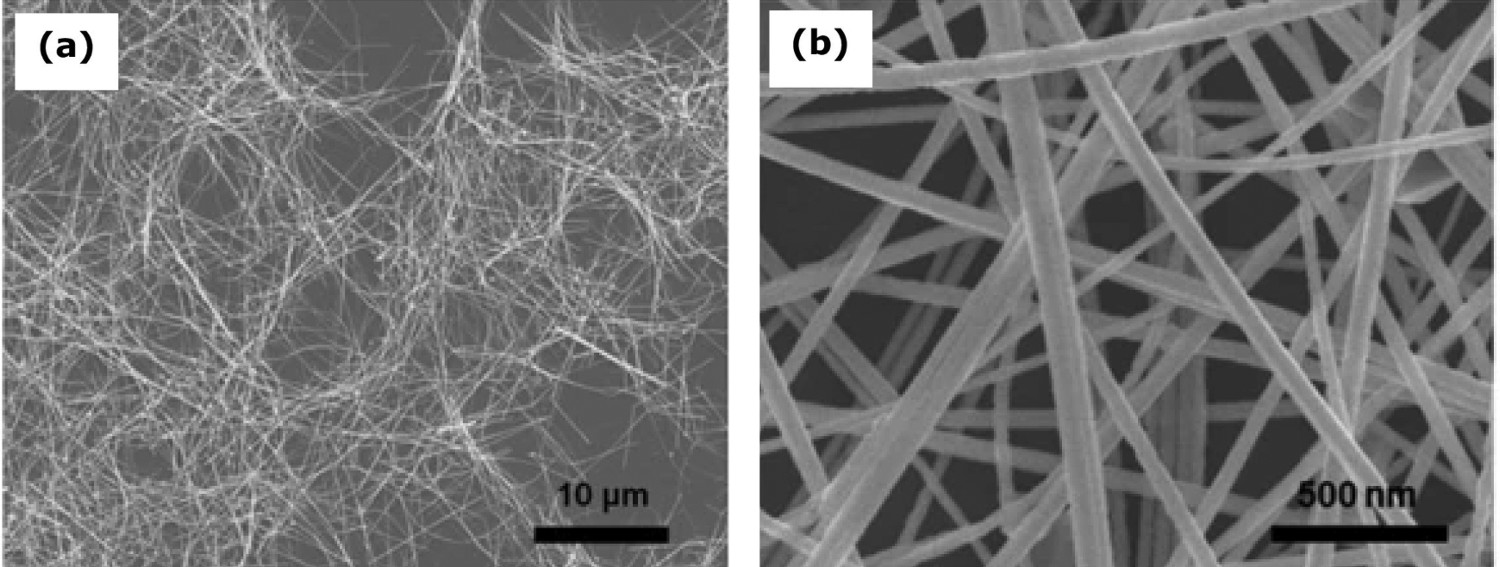
As seen through various examples, copper NW's have shown high sensitivity to some chemicals. AZO passivation layer deposited Cu NW sensor has shown to have high corrosion resistance and thermal oxidation resistance up to 160°C. Some of the electrochemical behaviours of the Cu NW-modified sensor include high current and sharp potential response. High sensitivity of electrochemical Cu NW sensor helps in detecting nitrate at the micromolar level and has demonstrated efficient working ability at the interface condition [204,207]. Highly sensitive property of CuNW could detect slight change at the interface conditions. Key characteristics such as high corrosion resistance and current density are the main advantages of the CuNW sensor, which could provide a long service life for interface condition monitoring.
Silver nanowire
Silver nanowire (Ag NW) is an excellent metallic conductor with high electrical and thermal conductivities applied in many electronic devices with a diameter range of 10-200 nm and a length range of 5-10 µm [208,209]. Ag NW can be synthesised using various techniques such as chemical reduction, polyol, electrodeposition and biological. The schematic of nucleation, growth, resistance values and SEM images of the Ag NWs are shown in Figure 23. It has been demonstrated that the growth of Ag NW is affected by synthesis temperature and the concentration of silver nitrate [210]. Polyol synthesis is a large-scale fabrication of Ag NW with uniform diameters [212]. Polyol synthesis is a liquid phase method. In this process, the temperature influences and reduction of polyol alcohol can control the nucleation and growth of Ag NW. The morphology of Ag NW plays an essential role in optical and electrical properties, which are controlled by way of synthesis. Graphene or carbon nanotubes can be combined with Ag NW to enhance their optical and electrical properties [213]. Naito et al. [214] demonstrated that a conducting film of the reduced graphene oxide layer (of thickness 20-25 µm) can be coated on Ag NW to prevent corrosion against sulphur vapour.
Silver nanowire (Ag NW): (a) Synthesis process of silver nanowires (reproduced under the terms of the Creative Commons Attribution NonCommerical 3.0 Unported License [210] Copyright 2018, Royal Society of Chemistry), (b) advanced multilayer sensor and (c) PDMS-Ag NWs calibration curve of resistance behaviour with change in temperature reproduced under the terms of the Creative Commons Attribution (CC BY) license [136] Copyright 2017, MDPI, (d, e) SEM images of silver nanowire at two difference magnifications (reproduced with permission [211] Copyright 2004, American Chemical Society).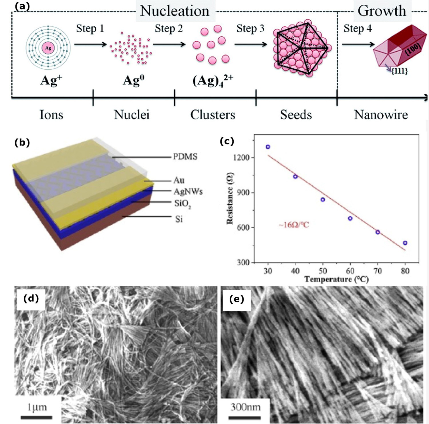
Owing to high electrical and thermal conductivities, application of Ag NW as temperature sensor (measurement based on resistance changes) can be a good choice, as demonstrated with the use in person's mouth to measure the human temperature [187]. It was observed that with the temperature increases from 30°C to 80°C, Ag NWs resistance decline by 21% and the resistance of Ag NWs increases when the relative humidity increases from 30% to 80% [187]. High-level temperature sensitivity can be achieved by eliminating the relative humidity influence in the Ag NWs resistance. To do this, polydimethylsiloxane (PDMS) can be deposited on Ag NWs by ion sputtering technique. By doing so, the PDMS could effectively help avoid the influence of relative humidity in the resistance of Ag NWs. Measurement through PDMS – Ag NWs-based temperature sensor shows good reproducibility and its temperature sensitivity reaches ∼16 Ω/°C at the temperature range of 30°C–80°C. The layer of PDMS-Ag NWs deposition and response to the temperature is shown in Figure 23b,c [187].
Owing to high electrical and thermal conductivity of Ag NWs, high-level sensitivity of temperature monitoring can be achieved in the biomedical field with its sensors [208]. It has been demonstrated that PDMS on the Ag NW improves sensitivity along with good reproducibility [187]. This means, Ag NW placement at the interface condition could help enhance the sensitivity of sensor-based monitoring and find the temperature changes accurately. Low fabrication cost is among the advantages of silver nanowire which could be used at the interface to monitor large surface areas, with potentially minimal installation price.
Silicon nanowire
Silicon nanowire (Si NW) is a semiconducting material that has unique electronic, optical, mechanical, chemical and thermal properties [215]. Si NW is fabricated by different approaches such as vapour liquid–solid (VLS) growth, thermal evaporation oxide-assisted growth (OAG), laser ablation, chemical etching, solution-phase synthesis, molecular beam epitaxy [216]. The scheme of the silicon nanowire sensor and an example microscopic image of Si NW is shown in Figure 24a,b. Si NW electronic properties are adjusted by the addition of dopants. At the same dopant concentration, the resistivity of Si NW is about one or two orders of magnitude is higher than the resistivity of bulk silicon [219]. Si NW has piezoresistive properties which are indicated that Si NW applications in electromechanical devices as a senor and an actuator. Sohn et al. [220] indicated that the mechanical properties of Si NW do not gets affected by size if diameter of the nanowire is above 100 nm. The thermal conductivity of Si NW (142 Wm−1 K−1) is very close to bulk silicon (150 Wm−1 K−1). The surface roughness of Si NW makes little effect on thermal conductivity and the porosity of Si NW makes a drastic reduction in thermal conductivity [221].
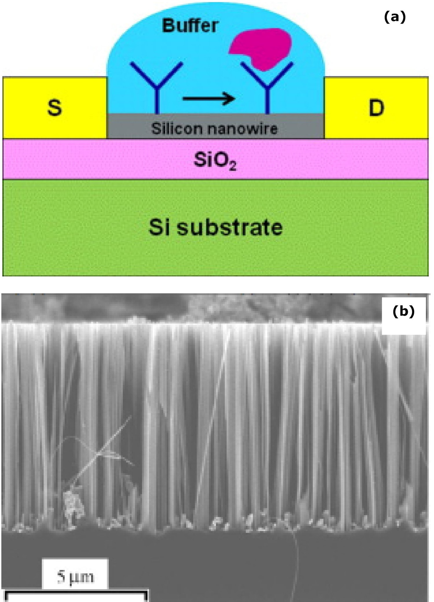
Silicon nanowires-based biosensors are highly sensitive, label-free to detect cancer, cardiovascular disease, infectious disease, seasonal virus detection in early stages. Specifically, Ag NW biosensors can be applied to screen cancer in the tissue or blood in extremely low concentrations along with cost-effectively and high analytical selectivity. The sensor surface absorbs the molecules and its conductivity changes based on concentration charge changes on the sensor top layer. The advantage of Ag NW in the biosensor is that it requires a very small amount of biological liquid for diagnosis [217,222,223].
Silicon nanowire-based biosensors are highly sensitive to detecting biomolecules. Silicon nanowires-based sensor has made an incredible impact on cancer screening or blood analysation [222]. Such sensor offers the opportunity for earlier detection of oncological pathologies [223]. Considering various functions and features, highly sensitive Ag NW placement at the interface could help improve ion collection and could sense small amount of electrolyte at the interface.
Titanium dioxide nanowire
Titanium dioxide nanowire (TiO2 NW) has various applications such as optoelectronics, electronic and electrochemical nanodevices [225]. Single crystalline TiO2 NW is typically fabricated by the chemical vapour deposition method. The electrical conductivity of TiO2 NW is normally low (2.2438 × 10⁻⁴ Scm−1 (for 40 mg weight of TiO2)) [226]. However, it can be enhanced through a combination of chemical compounds. Polymethyl methacrylate (PMMA) has high stability, excellent weather ability, optical clarity and excellent dimensional stability. PMMA can be provided the potential to reduce gas permeability, improve physical performance and increase heat resistance. Hybrid PMMA/TiO2 NW (PA/AgNO3) is fabricated by emulsion polymerisation, and its maximum electrical conductivity is 20 Scm−1 [224,226]. The fabrication of the TiO2 nanowire by a modified hydrothermal process is shown in Figure 25a. The diameter of the TiO2 nanowire directly impacts density, thermal conductivity and thermal diffusivity. With the diameter increase from 250 to 370 nm, the thermal conductivity improves from 1.3 to 4.9 Wm−1K−1, density rises from 1430 to 3180 kgm−3 and thermal diffusivity goes up from 1 × 10⁻⁶ m2/s to close to 2 × 10⁻⁶ m2/s, as shown in Figure 25b [228]. The high thermal conductivity needs high filler loading, which often reduces various mechanical properties [230].
(a) Synthesis of TiO2 nanowire by modified hydrothermal process (reproduced with permission [227] Copyright 2016, Elsevier) and (b) relationship of diameter with thermal conductivity, thermal diffusivity and density (reproduced with permission [228] Copyright 2012, IOP Publishing), (c) SEM image of TiO2 nanowire (reproduced with permission [229] Copyright 2014, Wiley).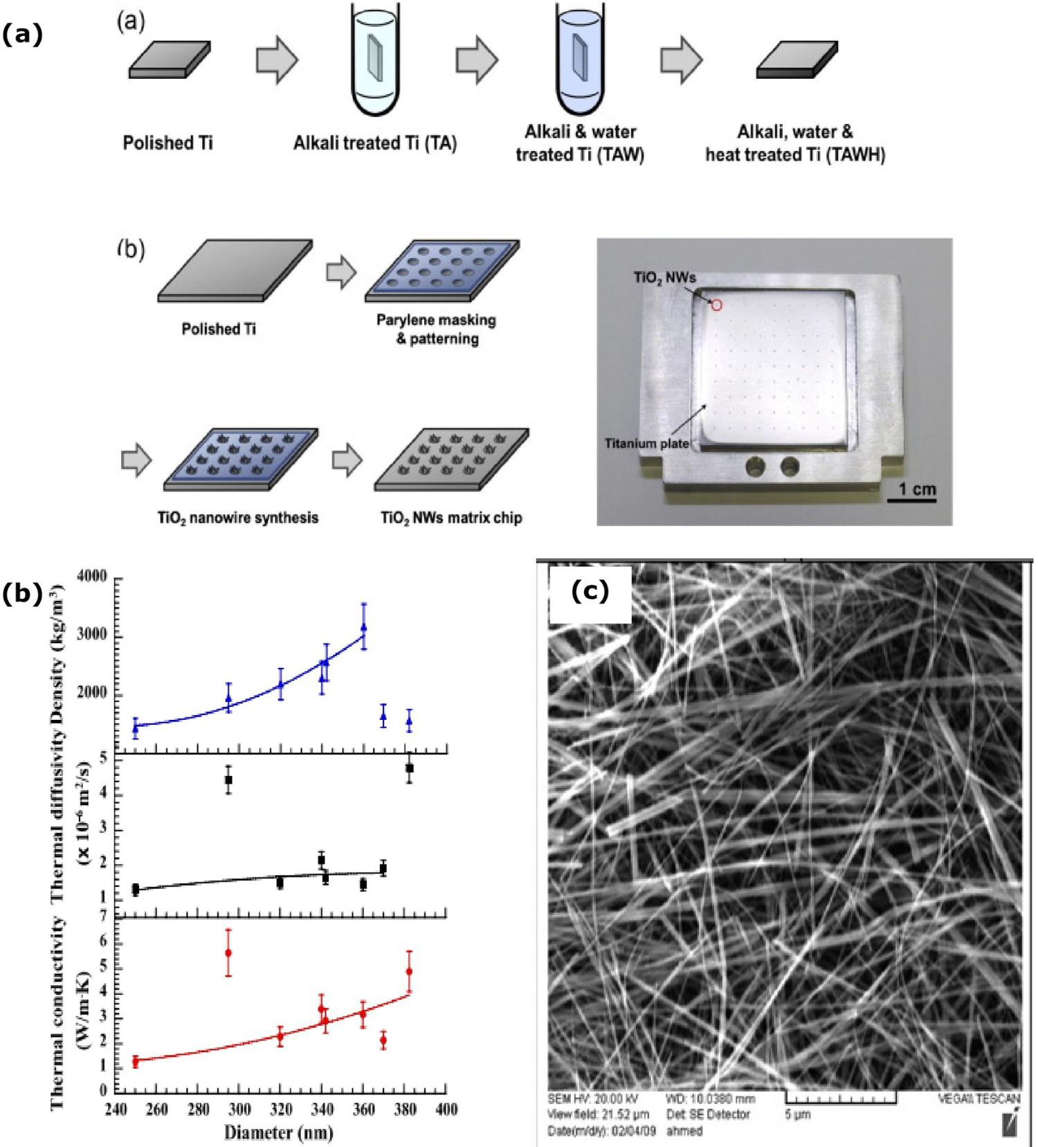
An example microscopic image of TiO2 nanowire is shown in Figure 25c. Apart from range of usage of TiO2 nanowire [231] (e.g. O2/H2/CO gas sensor, biosensor, photo-induced super hydrophilicity, purification of pollutants, absorption of OH−), it can also be used to detect variable gases including combustible, flammable and toxic gases. TiO2 (in the form of nanoparticle) gas sensor can show high sensitivity, quick response time and recovery time under an annealing temperature of 300°C. However, after annealing at temperatures above 600°C, the amorphous TiO2 structure could change into anatase and further anatase changes to rutile, which could reduce the sensor's sensitivity. The layer of TiO2 on the humidity sensor could decrease conductivity and could increase the dielectric constant when humidity forms on the sensor layer. The layer could facilitate the humidity absorption because of the TiO2 larger surface area. The TiO2 nanostructure sensor has the advantages of high sensitivity, fast response, low cost and long-term stability [232 234]. The modified TiO2 (nanocrystalline) electrodes could be cost-effective alternative to traditional inorganic silicon-based photovoltaics. 3D TiO2 nanowire could make positive changes in the solar panel, such as enhancing the hole injection efficiency panel and increasing light-harvesting efficiency, improving the electron-transport property [235,236].
Nanowire properties.
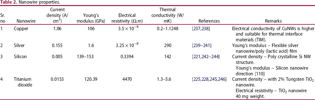
Hybrid and multi-functional sensing methods
Hybrid and multi-functional sensing are advanced techniques to detect and monitoring of the interface corrosion where each sensor could complement measurement findings. However, each sensing method can have certain limitations of working environment, and data collection. Collection of various environmental conditions and corrosion level, needs one or more sensors which can provide precise and quick information about various interface conditions. Hybrid sensing approach could make an immense impact such as avoid system failure, production loss and interface corrosion-related accidents. This section provides an overview about some hybrid sensing approaches that could potentially enhance corrosion monitoring at interface.
Combination of AE and optical fibre sensors
Figure 26 shows schematic diagram of combination of AE and optical fibre sensor [11]. This is with the aim to make the combination of two sensing methods to simultaneously detect corrosion and moisture levels at the interface of an insulated pipeline.
Combination of acoustic emission and optical fibre sensor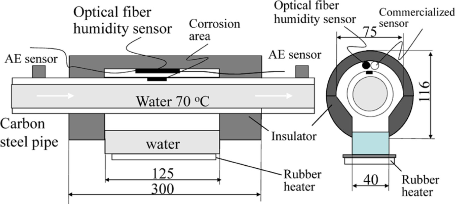
In this example by Cho, Tamura and Matsuo [11], an AE sensor was placed outer region of the insulation on the pipeline's surface. AE signals are produced when cracks or corrosion, humidification and drying happen on the pipeline's surface. Additionally, the corrosion waste at the interface increases the stress, which releases AE. The location of the AE source can be determined based on the signal's arrival time to the sensor. AE signal propagation and velocity are based on the shape and mode of propagation and the signal travel time distance. AE sensor collects the signals and transfers them to the data storage through a preamplifier and signal conditioning unit. In this example, an optical fibre cable was placed parallel to the object's surface at the interface. The supply of laser light from the light source released into the coating and the transmitted laser power changed with moisture. The coating absorbed moisture and changed its refractive index. Single layer of CoCl2 and PVA was coated on the optical fibre to measure the humidity of 60-80%. However, the laser power decreases at 90% humidity condition and above. 5 wt-% pullulan is coated on the optical fibre to enhance the work above 80% humidity level. At humidity level below 60%, the reflective index of coating changes owing to the temperature changes and the reflective index of changes with humidity should be small. The sensing coating enhances the sensor's performance in the high-level humidity and the temperature range of 10°C to 50°C. The sensitivity increased with the application of the sensitive coating on optical fibre. On the outer limit of the measuring interface, the photodiode collects the transmitted laser power. At high moisture levels, the laser light shows high intensity [11]. The AE and optical fibre sensor combination monitors and analyses the corrosion and moisture at the interface. However, it is essential to note that corrosion should be active for continuous monitoring in this method.
The combination of the AE and optical fibre sensors could monitor corrosion and humidity under insulation conditions, as studied by Cho, Tamura and Matsuo [11]. However, AE sensor placement at the outside of the insulation layer and humidity sensor laid slightly away from the interface do not provide an exact interface condition. Combination of hybrid sensors sensing ability can be improved through sensor placement very close to or at the surface, and as summarised above, consideration of additional sensing method through nanowire-based sensor application could potentially enhance electron collection strength.
Combination of chloride and pH sensors
Du et al. [247] initiated the non-destructive method of chloride and pH sensors combination to evaluate the chloride ions concentration and pH level at the interface between concrete and steel. The Ag/AgCl electrode prepared by electrochemical anodisation worked as a chloride sensor, and Ir/IrO2 electrode prepared by thermal oxidation in carbonate served as a pH sensor (shown in Figure [29]) and combinations of sensors were designed with epoxy at the interface to prevent the short circuit, and it was embedded in concrete close to the interface of steel. It is well known that Ag/AgCl has the advantage of good stability, small in size and easy fabrication. Compared to the other metal oxide electrodes, iridium oxide shows better stability in a wide range of pH, higher resolution and quick response time even in high pressure and temperature conditions. In their investigation by Du et al. [247], sensor embedded concrete block was immersed for different time periods in the 3.5% NaCl solution to analyse the measuring effect of sensors. The Ag/AgCl electrode measured the potential change based on chloride ions concentration very fast and stable. The sensor measured the maximum level of chloride ion concentration at an interface after 12 days of immersion, followed by small fluctuations in chloride concentration. Initially, the chloride ions concentration difference between the interface and outer surface was large, which led to quick diffusion. The Ir/IrO2 electrode (which served as a pH sensor) measured the values with stability. Results showed that initial pH decreased quickly owing to the diffusion of H+ and OH− happened fast for neutralisation. Overall, the sensor-based measurements (indicating chloride and pH changes) at the interface showed the corrosion behaviour of the reinforced steel [247]. The combination of two sensors (chloride and pH) showed a better measurement of the interface conditions with stability and fast response time. However, owing to the sensor measurement probes being in one place, the sensor measures conditions locally.
Combination of chloride and pH sensor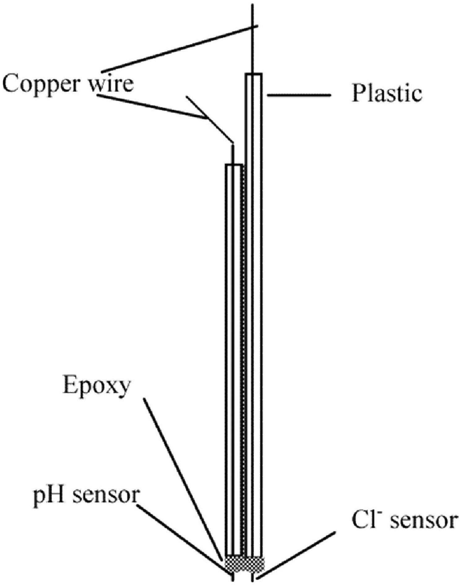
Multifunctional sensors
Monitoring the corrosion of steel in the reinforced concrete structure is not easy owing to the steel embedded in the concrete. Measuring the pH and chloride ions in the reinforced concrete is a challenging process to quantify. As shown in Figure 28, a combination of multifunctional sensors can be useful at the reinforced concrete interface to monitor the corrosion, chloride ions concentration and pH levels [15].
Multifunctional sensor scheme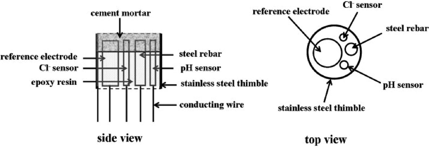
Interface at the steel-concrete is normally dominated by the various concentration of the elements such as hydroxide, potassium, sodium, calcium and sulphur. The pH sensor contains the Ir/IrO2, which can be prepared by various methods such as electrochemical oxidation, electrochemical deposition, sputtering coating and thermal oxidation in carbonate. The multifunctional sensor contains the pH sensor, chloride sensor and reference electrode in the reinforced concrete. The pH sensor provides pH changes in the reinforced concrete, and the chloride sensor indicates the chloride ions concentration changes. The combination of the pH and chloride sensors results can determine the corrosion of the steel in the reinforced concrete. The high alkalinity of the reinforced concrete forms the passive layer on the steel and gives long durability. Steel service life and corrosion behaviour are based on the reinforced concrete environmental conditions which change frequently. Multifunctional sensor can be used to monitor various changes. The chloride ions concertation drops on the concrete increase the corrosion on the steel. Carbonation process in the reinforced concrete reduces the pH to less than 9. Sudden drop in pH level can destroy the steel's passive layer and initiate corrosion. Additional variables such as temperature, concrete porosity, moisture content and especially porosity is also vital for the steel corrosion in the reinforced concrete structure. Calibration of the sensors could not stay for an extended period, potentially affecting the efficiency of the monitoring are the disadvantages of embedding the sensor at the concrete interface [15,79].
As demonstrated through example (e.g. [15]), interface monitoring of reinforced concrete sensor design is more advanced than corrosion under insulation sensor design. In such measurements, chloride and pH sensors are embedded in concrete close to the steel bar. However, as one of the main disadvantages of this sensor assembly, calibration of the sensor does not stay for an extended period [15]. The representation of multifunctional sensor interface condition measurements has been discussed above. Various hybrid or multifunctional sensor designs have been proposed to investigate the interface conditions. It appears that interface condition monitoring with multifunctional sensors is viable option with some disadvantages, which can be overcome through advanced and smart materials usage. Advanced materials and nanowires could improve the sensitivity of the reinforced concrete interface monitoring, providing values with enhanced sensor stability to work in harsh environments without quick failure. Also, an intelligent sensor design and assembly could allow various sensors on one sensor array to monitor various conditions effectively.
Concluding remarks
Interfacial corrosion involves corrosion at the interface between the materials or objects primarily owing to the ingress of moisture. The interface could be between metallic substrate (coated or uncoated) and insulation, metal, rubber, concrete or clay. At the interface, the visibility of corrosion is little or none, and based on the environmental conditions, the corrosion rate varies, and therefore, sensor-based monitoring methods could be useful route for corrosion and other interface conditions analysis (including those which measures a surrogate, i.e. quantifying moisture, temperature, pH and other changes or degradations at the interface). This review presents sensing, monitoring and analysis methods (mainly based on laboratory systems) of corrosion at the interface or in the vicinity. The review starts with fundamentals of electrochemistry associated with corrosion (i.e. anodic and cathodic reactions with the presence of electrolyte). It also summarises type of corrosion, and how these can be dependent on the environment around the interface, such as moisture, temperature, pH, gases and other changes or degradation.
As reviewed, there are numerous sensing methods which have been used to monitor interface condition near or in the vicinity (e.g. electrochemical noise, electrochemical Tafel polarisation, electrochemical impedance spectroscopy, electrochemical galvanic sensor, electrical resistance, AE, optical fibre humidity sensor, thermocouple sensor, pH sensor and chloride sensor). This review also provides an overview about advanced materials which could be considered as alternative sensing material (and their design as sensor) to monitor conditions at the interface region, such as indium tin oxide, zinc oxide, zirconium oxide, lead zirconate titanate, carbon nanotube, various nanowires (copper, silver, silicon, titanium oxide). Additionally, this review summarises the hybrid and multi-functional sensing methods which could be considered as advanced means to monitor various conditions at the interface region.
The study shows a research gap in the sensing materials selection, their design and assembly, deployment of sensors, integration of multi-functional sensors, reliability and interpretation of the data that can be critical to advancing and exploiting their potential for digitisation and digitalisation of corrosion. Currently available sensing methods have limitations, as electrodes or sensors are placed away from the interface conditions. The placement of electrodes away from the interface affects the measurement quality. Since every sensing material and method has working limitations, it is recommended to consider those sensor materials, their design and assembly (at the interface or in the vicinity) which could monitor the interface conditions both qualitatively and quantitatively, potentially complementing the existing methods.
Since the evaluation of corrosion and identification of prevalent forms of active corrosion are very important for interface corrosion monitoring, it is recommended that the sensor materials need to be highly sensitive and sustainable to measure corrosion reactions in low to mild corrosive environmental conditions. The materials should be able to detect changes in the environmental condition efficiently, and should contain multifunctional properties such as exceptional chemical, electrical, mechanical and thermal properties. It is also recommended that the moisture and temperature sensors should be able to detect very small environmental changes at the interface or in the vicinity. The pH sensor should be sensitive enough to find the changes at the interface even in dry or semi-dry conditions. Also, the selected sensor materials should be able to be built as part of smart structures such as sensor networks and actuators, while the sensor location, installation and access for the maintenance are important consideration.
Collecting various environmental conditions and corrosion levels requires one or more sensors which could precisely help to find the location and quantify the various interface conditions. Hybrid sensing approach could make an immense impact, such as avoiding system failure, production loss and interface corrosion-related accidents. The hybrid and multi-functional sensing should be able to detect and monitor the interface condition where each sensor could complement measurement findings. However, each sensing method can have certain limitations of working environment, and data collection. Since multiple sensors provide opportunity to monitoring various interface conditions, the sensitivity and reliability of sensors could impact the trustworthiness of the collected data. The array of sensors can be used to monitor the corrosion, moisture, hydrogen embrittlement, temperature, pH, gases and other environmental conditions at the interface to find the changes precisely. Collected data (through a wireless or wire-based system) could pass-through monitoring system and could be stored in the designated storage place for an extended period, which can be used for comparative analysis. Finally, the reliability of collected data needs to be investigated which defines the fault at the interface without removing the outer layer ensuring a safe operational environment.
The overview presented through this review was mainly based on laboratory systems, is not exhaustive but provides the complexity involved and solution needed to detect and monitor corrosion and environmental conditions at the interface region.
Footnotes
Acknowledgements
While developing this extensive review, we acknowledge critical, constructive and impartial feedback by corrosion specialists and sensor experts at U.K. based company (CorrosionRADAR Ltd).
Disclosure statement
No potential conflict of interest was reported by the author(s).