
Abstract
The Canadian Nuclear Waste Management Organization (NWMO) has chosen a used fuel container (UFC) design that consists of an inner steel core and outer copper coating that resists corrosion in the anaerobic underground. However, in these anaerobic conditions, microbiologically influenced corrosion (MIC) can contribute to UFC corrosion if sulphides are present in the repository. Therefore, an engineered barrier system (EBS) consisting of bentonite blocks and pellets has been designed to inhibit production of sulphide by microorganisms and impede the movement of sulphides from the host rock to the UFC. Initially, the bentonite within the deep geological repository will contain no sulphides and it will take time for sulphide from the host rock to saturate the repository. To examine the transient effect of sulphide transport and the effectiveness of the EBS, a 3D numerical model was developed capable of simulating the diffusive transport of sulphide within the NWMO repository. The model was developed using COMSOL Multiphysics, a finite element software package. The developed model included the NWMO placement room, as well as a stand-alone UFC package. Conservative assumptions such as constant-concentration boundary condition and transport-limited corrosion were assumed. The time-dependent analysis predicted the inflow of sulphide into the EBS over time, and the results showed that a steady-state condition would be reached in over 2,000 years in the placement room. The model also showed that the highest sulphide flux occurred at the semi-spherical end caps of the UFC and consequently, that corrosion from sulphide diffusion would not be uniform over the container surface.
This paper is part of a supplement on the 6th International Workshop on Long-Term Prediction of Corrosion Damage in Nuclear Waste Systems.
Introduction and background
The Nuclear Waste Management Organization (NWMO) is implementing Adaptive Phased Management (APM), the approach selected by the Government of Canada in 2007 for long-term management of used nuclear fuel. The goal of APM is long-term containment and isolation of used nuclear fuel in a deep geological repository (DGR) constructed in a suitable rock formation in either sedimentary or crystalline rock at a depth of approximately 500 m [1]. The current design consists of a steel container surrounding the used fuel that provides the strength needed during storage. The steel container is coated with copper, a naturally stable metal, used to protect the container from corrosion. Finally, the used fuel container (UFC) is encased within a bentonite package and stored in the placement rooms in the DGR.
Bentonite is a naturally occurring clay-rich sediment containing montmorillonite, a smectitic clay mineral that has a high cation exchange capacity and swells upon contact with water. These characteristics make highly compacted bentonite (HCB) an ideal engineered barrier system (EBS) material. The low water activity and high swelling pressure of HCB suppress microbial activity and the related production of sulphide that could cause microbiologically influenced corrosion (MIC) [2–4]. HCB can also slow groundwater infiltration, provide a thermally conductive medium, and retard the movement of radionuclides in the event a UFC breach occurs.
MIC is the largest UFC corrosion contributor that also has the highest uncertainty. While the outer copper coating of the UFC limits corrosion, in the anaerobic underground MIC can contribute to UFC corrosion if sulphides are present in the repository [3]. At present, the Canadian ‘far-field’ MIC corrosion allowance is 1 mm over 1 million years [5]. This is a conservative, generic value, which is based on the supposition that microbial communities can develop outside of the EBS to produce a continuing sulphide concentration throughout the repository that will gradually diffuse to the container surface. Owing to the suppression of microbial activity in the near-field (buffer, sealing materials and container), the generic ‘near-field’ MIC corrosion allowance is 0 mm over 1 million years [6,7]. Notwithstanding where the sulphide comes from, copper can freely corrode once HS− reaches the UFC surface:

In order to examine the effectiveness of the EBS, a 3D numerical model was developed capable of simulating the diffusive transport of sulphide within the NWMO EBS. The model was developed using COMSOL Multiphysics, a finite element software package. The developed model included two different systems: first a stand-alone UFC package and second the entire NWMO placement room. Conservative assumptions such as constant-concentration boundary condition and transport-limited corrosion were assumed.
Method
The model assumed isothermal, water-saturated conditions, and simulated diffusion of far-field sulphide through the repository to the UFC. Groundwater flow through the bentonite was assumed to be negligible and transport of MIC agents was assumed to be dominated by diffusion. Diffusion was assumed to be governed by Fick's first law and controlled by an effective diffusion coefficient, which accounts for tortuosity, dispersion, and porosity of the bentonite. For these simulations, an effective diffusion coefficient of 1 × 10⁻¹¹ m2 s−1 was used [5].

The geometries for all modelling scenarios presented in this report were generated using COMSOL Multiphysics with changeable parameters (parametric modelling) to allow scoping calculations. The UFC package geometry consisted of bentonite surrounding a cylindrical UFC with hemi-spherical ends (Figure 1). The UFC package had a square side of 0.965 m and a length of 2.915 m [9]. The geometry of the UFC package resulted in a minimum bentonite cover of 0.2 m along the cylindrical area of the UFC, as well as at the hemi-spherical end caps. An additional 0.100 m of bentonite cover was added by the gap fill in the placement room.
On the left: The NWMO UFC package consists of a UFC coated in corrosion-resistant copper. The UFC was placed within a bentonite package roughly 1 m × 1 m × 3 m. On the right: A 10 m segment of the NWMO placement room with 13 UFC packages and surrounding HCB and bentonite pellet backfill.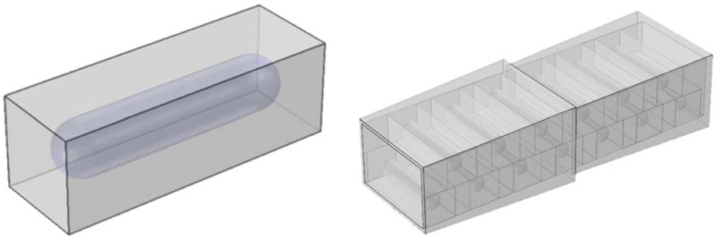
A placement room within the DGR is approximately 400 m long (depending on the host rock); however, owing to symmetry, it was sufficient to model only a fraction of this length. Therefore, the placement room was represented by a 10 m segment. Within the placement room, each UFC package was separated by bentonite blocks and backfilled with bentonite pellets.
Boundary conditions
The far-field sulphide concentration was conservatively assumed to be 3 ppm and was applied as a constant-concentration boundary condition around the perimeter of the placement room adjacent to the host rock. This value was chosen to represent the maximum hydrogen sulphide concentration in pore water found in the literature [5] until a more appropriate site-specific value can be determined.
The copper surface of the UFC was also assumed to have a constant-concentration boundary condition. In this case, a value of 0 ppm was used since it was assumed that the corrosion reaction was transport limited and any sulphide arriving at the UFC surface will be consumed instantly. Having both concentration boundaries at the inner and outer model domains resulted in a flux sulphide being driven through the system.
Time-dependent analysis
Initially, the EBS was assumed to have no sulphide present. Over time, the sulphide diffused through the EBS towards the UFC surface. Figure 2 shows the results from the model and illustrates that sulphide flux started from zero and increased over time until it reached the steady-state condition. Values for both the single UFC package and placement room cases are reported relative to the maximum flux seen for a single UFC package. Both average and maximum rates are shown and the maximum flux occurred at the hemi-spherical end cap of the UFC. The larger surface area of the outer UFC package relative to the canister surface causes sulphide diffusing inwards to concentrate on the end caps. Both UFC and placement room models reach steady state early on in the 1-million-year time span, with the placement room reaching steady-state sulphide concentrations after 2,000 years. Figure 2 highlights the expected difference between regions of maximum and average sulphide flux, indicating the importance of capturing the 3D effects of sulphide transport in the model; a 1D or 2D would not capture the behaviour.
Time-dependent analysis of corrosion rates due to diffusion of sulphide through the EBS for both the UFC package and placement room. Values for both plots are normalised relative to the maximum sulphide flux found in the UFC package model.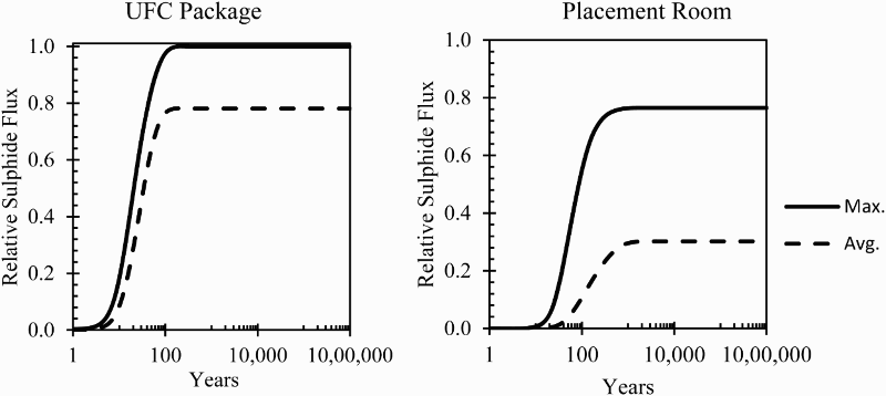
Preferential pathways
The time-dependent analysis used constant-concentration boundary conditions surrounding the entire model. However, it may be the case that a sulphide source is more localised, acting as a hot spot or local source. It is also useful to consider the effects of preferential pathways for sulphide transport within the repository. Such a situation could be envisioned, for example, where bentonite is not ideally backfilled leading to microbial growth not completely suppressed by the bentonite. To simulate such a preferential pathway, it was presumed that a failure of the bentonite backfill had occurred leading to a fracture, or line source, acting on the UFC package (Figure 3).
Preferential pathway geometry assuming the outer bentonite layer of the EBS has failed resulting in a sulphide line source adjacent to the UFC package.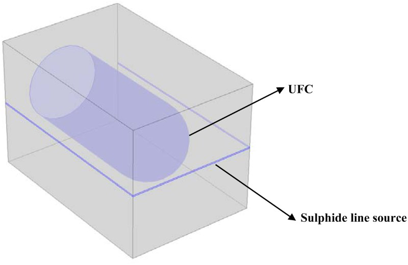
To model this scenario, the line source, represented by a 1 mm fracture plane, was placed around the entire perimeter of the UFC package at midpoint where the least amount of bentonite cover was present (resulting in the worst-case scenario for a line source). A 3 ppm constant-concentration source of sulphide was defined along the line source while 0 ppm was assumed over the remaining surface of the UFC package. The results showed sulphide fluxes to the UFC surface that were orders of magnitude smaller than models with sulphide surrounding the entire placement room (Figure 4). Even with high sulphide concentrations at locations of minimum bentonite cover, the 1 mm thick fracture acted as a significantly smaller source. Diffusion of sulphide into the bentonite adjacent to the fracture also reduced fluxes to the UFC surface. In this case, although the bentonite backfill was compromised, the resulting preferential pathway was small and its effects were negligible compared to sulphide sources covering the entire model.
Preferential pathway scenario, where a 3 ppm, 1 mm line source acting at the surface of the UFC package at the location of minimum bentonite cover. Sulphide flux is normalised relative to the maximum sulphide flux found in the UFC package model in Figure 2. Dimensions are given in meters.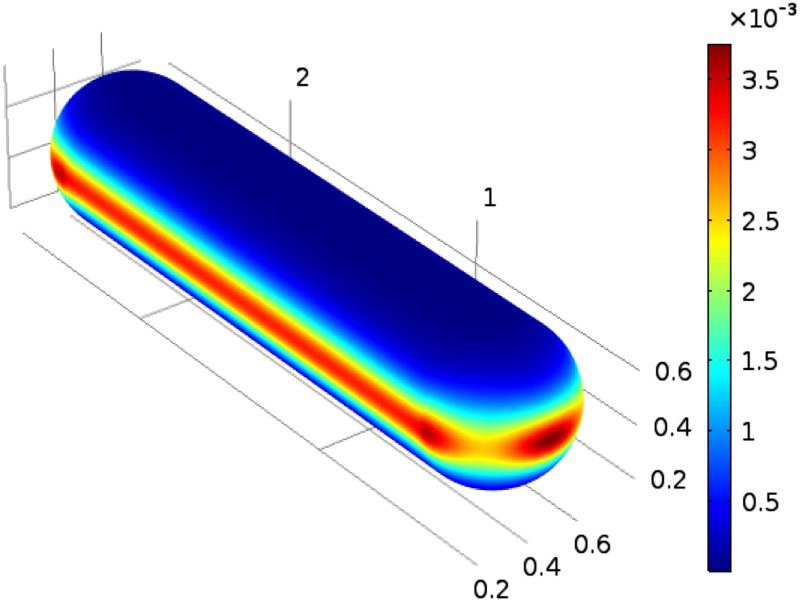
Conclusion
In this study, the time-dependent diffusion of corrosive species through the EBS was simulated using COMSOL assuming isothermal, water-saturated conditions. Sulphide diffusion was modelled to examine the potential MIC of the UFC located in a Canadian repository. The results indicated that corrosion from sulphide diffusion may not be uniform over the container, as assumed by previous 1D models. The semi-spherical end caps of the UFC were predicted to have the highest values of MIC owing to the geometry of the UFC package. This was a result of the larger surface area of the UFC package relative to the UFC surface, which causes sulphide diffusing inwards to concentrate on the end caps. Therefore, future work investigating diffusion of sulphide through bentonite should continue to incorporate 3D transport. Other model assumptions and limitations should also be revisited. Specifically, the assumption of isothermal conditions is not realistic. The heat from the UFC is likely to affect the saturation profile surrounding the UFC potentially causing a dry bentonite zone that would affect sulphide transport until the system cools and re-saturates. In addition, once a site has been selected and the geology of the repository is understood, the model can be extended to capture the likely preferential pathways unique to that site. The COMSOL model can also be used for site-specific scoping calculations and enhancement of the EBS.