
Abstract
Cold spray and laser powder bed fusion deposition processes were explored and found to significantly increase the peak force and fracture energy of the press hardened boron steel–aluminium joint. The use of 250 µm thick 316L metallic interlayers was resistance spot welded to an AlSi-coated press hardened steel and 6022-T4 aluminium alloy. Moreover, aluminium penetration within the deposited 316L promoted a mechanical locking effect which was assessed by increasing the hatch spacing in the laser powder bed fusion process from 100 to 200 µm.
Keywords
Introduction
The implementation of advanced multi-materials for the body-in-white design has seen tremendous growth in the transportation industry as the need to reduce the carbon footprint and improve the energy consumption of electric vehicles increases [1]. The primary joining process used in the automotive industry is resistance spot welding (RSW) for its efficiency, process control, and cost compared to other processes [2]. However, implementing the multi-material concept has brought challenges, specifically regarding joining Al–Fe due to their metallurgical incompatibility [3–5]. As a result, new and innovative joining technologies have gained popularity, specifically in the automotive sector [6,7].
Specifically, concepts such as magnetic-assisted (MA) RSW, weld bonded adhesives, and metallic interlayers have been explored with great success [8–10]. The introduction of an external magnetic field during RSW has been shown to create a refined microstructure, inhibit the formation of the oxide film and pore defects, and reduce the intermetallic compound layer thickness. Weld bonded adhesives increase joint strength as the adhesive layer between the sheets minimises the stress surrounding the weld nugget [11,12]. Thus, carrying part of the rotating stresses acted upon tensile shear loading conditions [13]. On the other hand, metallic interlayer characteristics such as thickness and composition are essential in affecting the RSW process and mechanical testing. The use of an aluminium 4047 interlayer was assessed at various thicknesses and found that as the interlayer thickness increased, as did the mechanical performance due to the intermetallic layer being suppressed by Si atoms occupying vacancies in the c-axis of the Fe2Al5 orthorhombic lattice [14]. Besides this, cold spray interlayers have been assessed on a dissimilar RSW joint and similarly concluded that the thickness and composition of the interlayers heavily influence the intermetallic compound layer and the tensile shear strength of the RSW joint. The mechanical performance was improved by reducing the Fe–Al intermetallic layer [15]. Notably, metallic interlayers containing chromium have played an essential role in suppressing the formation of the brittle Fe–Al intermetallic [16]. The suppression of the Fe–Al intermetallic is determined to result from a decrease in the activation energy of Al, thus limiting the interaction between Fe and Al atoms [17]. The reduced interaction between Fe and Al atoms allows Cr atoms to occupy Al lattice sites and form (FeCr)xAly intermetallic compounds since Cr is a substitutional atom [18]. Thus, it has a significant effect on lowering the interdiffusion between FeAl3 and Fe2Al5. Notably, as the Cr content increases, the layer thickness of FeAl3 remains constant, and the Fe2Al5 layer thickness experiences a significant reduction [16,17,19].
Analogous work on using printed interlayers for dissimilar RSW is not present in the literature concerning the influence of interlayer density and composition effects on mechanical performance. The present work explored printed interlayers to join dissimilar RSW joints to address the above-mentioned questions. Furthermore, the laser technique's hatch spacing was investigated to determine its effect on the mechanical performance of the final resistance spot-welded joints.
Materials
The sheet materials used in this study were a 1.6 mm thick AlSi-coated press hardened boron steel (PHS) and a 2.0 mm thick aluminium 6022-T4. The PHS has a 30 µm thick coating with a composition of Al – 12 wt-% Si on the top surface layer and underwent the direct hot stamping process. The L-PBF powder consisted of 316L austenitic stainless steel with a particle size distribution (PSD) of 15–45 µm. The cold spray interlayer powder was 316 stainless steel with a PSD of 16–45 µm. 316L was selected because of its high Cr content and availability in powdered form. The use of ferritic grade stainless steel, such as 430, would be better than 316L since it is less expensive. However, 430 powder is not readily obtainable.
Methods
Interlayer deposition
The additively manufactured interlayers were deposited onto half of the PHS sheet dimensions using a 100W Concept Laser Mlab R additive machine. Half sheets were necessary due to the build volume limitations of the additive machine [90 mm × 90 mm × 80 mm]. Owing to aluminium's high reflectivity and thermal conductivity, the L-PBF deposition was unsuccessful after several attempts to deposit an interlayer. Thus, the L-PBF 316L material was printed on the PHS sheet. A 100, 150, and 200 µm laser scan spacing, commonly referred to as hatch spacing, was used to assess its effects on tensile shear loading conditions and was printed using 90W of power and a laser scanning speed of 600 mm s–1. The high hardness and ultimate tensile strength (550 HV and 2000MPa) made deposition trials of the 316L material unsuccessful onto the PHS; thus, the cold spray interlayer was deposited onto the 6022-T4 aluminium alloy using a VRC Metal Systems Inc. Gen III Max with a single 21 kW heater. Pure nitrogen gas was used with a pressure and temperature of 600PSI at 600°C. The two deposition processes were selected because of their ability to provide minimal distortion of the PHS and aluminium sheets on which they were deposited, strict interlayer thickness, and geometry control. All interlayers had a constant thickness of 250 µm.
Resistance spot welding
Figure 1 illustrates the RSW configuration. The aluminium sheet was placed on the positive electrode to consider the thermoelectrical Peltier effect, resulting in decreased applied heat. The electrodes used were RWMA Class 1 CuZr electrodes provided by Luvata Corp. The aluminium side electrode consisted of an F-type 16 mm face diameter with a 3 mm radius with the manufacturer designation FF25Z08. The steel side electrode was a dome B-type 8 mm face diameter (FB25Z24). The welding was carried out using a medium frequency direct current RSW machine at room temperature. The RSW parameters consisted of a three pulse approach. The welding current used was 16 kA with a welding time of 166 ms (10.0 cyc). The squeeze and hold time was 500 ms (30.0 cyc) and 240 ms (14.5 cyc). A 30 ms (2.0 cyc) cool time was used to reduce electrode cap degradation. The welding force applied was 5.3kN (1200 lbf). The welding schedule was kept constant for every interlayer condition to minimise the testing matrix.
Schematic of the interlayer deposition processes and RSW configuration: stage (1) interlayer deposited on the Al/PHS sheet using cold spray or L-PBF technique and stage (2) interlayer joint was RSW to either the Al or PHS.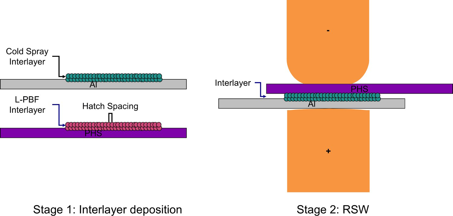
The aluminium nugget and intermetallic measurements were obtained through ImageJ software. Once welded, the samples were pulled in tensile shear configuration per AWS D8.9M using an MTS 810 machine. A total of three tests were performed for each condition using a quasi-static loading condition with a displacement rate of 1 mm min–1. The fracture energy was obtained from the area under the force/displacement curve at the peak force value, as sheets tend to bend and rotate after the peak force value is achieved.
Joint characterisation
The cross-sections of welds were prepared for metallographic analysis using standard metallographic procedures. The welded coupons were cut 0.5 mm from the weld centreline and were cold mounted in epoxy. The samples were ground and polished with diamond paste and a vibratory polish with 0.05 µm colloidal silica. Once polished, the samples were taken to a visible light microscope to analyse the nugget diameter. Microhardness measurements were also taken on a Leco LM-100AT system using a 200 g load, 10 s dwell time, and a 400 µm spacing based on similar literature and the AWS D8.9M standard [20,21]. Further characterisation of the intermetallic layer is required using an Apreo 2 scanning electron microscope (SEM) with energy-dispersive X-ray spectroscopy (EDS).
Results and discussion
As-deposited powder
The L-PBF process was unsuccessful at depositing the 316L onto the aluminium alloy. The differences in material properties between the stainless steel powders, such as thermal conductivity, material reflectivity, and intermetallic formation at the interface, resulted in the 316L interlayer separating from the aluminium surface. As a result, the L-PBF interlayers were deposited onto the AlSi-coated PHS. Cold spray is a solid-state process that relies on mechanical interlocking and metallurgical bonding to create a joint; thus, the elevated temperatures experienced in the L-PBF deposition do not exhibit the same problems. The deposition profile between L-PBF 316L and the cold spray 316L interlayer was used for density analysis. Based on the cross-sectional images, the L-PBF 316L and the cold spray 316L interlayers were 78% and 69% dense. The density decrease of the cold spray interlayer is a consequence of the cold spray process. The high strain rate during impact, along with the high rate of work hardening and strain rate sensitivity of austenitic stainless steels, make them resistant to plastic deformation, affecting the porosity of the interlayer [22]. Comparatively, the L-PBF process allows for greater control of the interlayer deposition by having the ability to adjust the laser scan spacing, speed, and power, all of which influence the density of the 316L interlayer. As a result, the L-PBF deposition increases by 11% for density.
RSW microstructure
Figure 2 shows the cross-sectional images of the no interlayer, cold spray, and L-PBF 316L interlayers. In Figure 2(a), a larger HAZ is observed in the no interlayer condition compared to the printed interlayer samples. The HAZ size is smaller in Figure 2(c) versus Figure 2(b). Besides this, in Figure 2(b), the PHS size exhibits much more indentation, indicating more severe heating during RSW. Also, the cold spray interlayer experienced expulsion, and the L-PBF 316L interlayer did not. The cross-sectional images depicted for both powder depositions illustrate the melting and solidification of aluminium into pockets of the L-PBF, and cold spray deposited interlayers. Because the cold spray interlayer is less dense, aluminium can penetrate much further to the interlayer-aluminium interface base than in the L-PBF process. The L-PBF 316L interlayer shows similar features with melting closest to the base of the interlayer-PHS partially due to the melting and solidification of some of the expelled coating during the RSW process. There were pockets of intermetallic regions closest to the base of both interlayer deposition processes. These regions experience higher resistance because there are close to the faying interface. Consequently, this resulted in the liquid aluminium penetrating the interlayer pockets.
Macrograph of RSW joints: (a) no interlayer, (b) cold spray 316L interlayer, and (c) L-PBF 316L interlayer. Chemical composition mapping of cold spray 316L interlayer at the aluminium interface. Chemical composition mapping of LPBF 316L interlayer at the aluminium interface.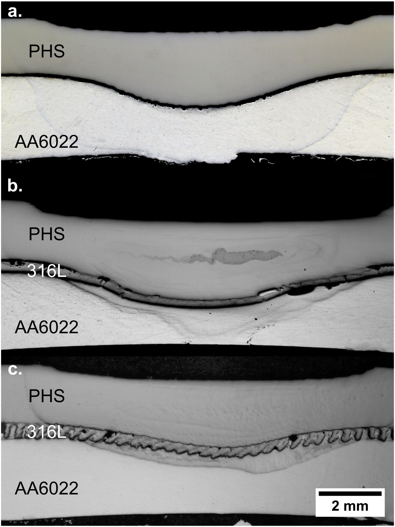
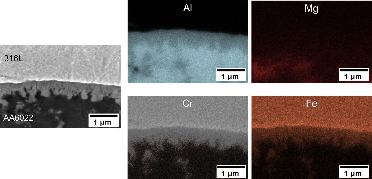
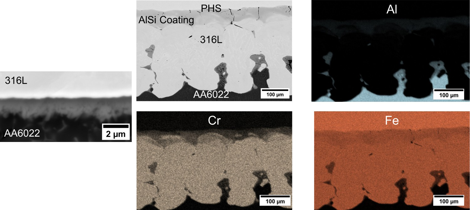
The chemical composition maps of the cold spray 316L interlayer shown in Figure 3 reveal the presence of Cr within the intermetallic layer. The thickness of the layer was 1.1 µm ± 0.1. The thickness of the no interlayer and LPBF 316L conditions were 1.8 µm ± 0.1 and 1.3 µm ± 0.1, respectively. Measurements were obtained from the top sections of the interlayer where first contact is made with aluminium and the centre of the welds, where the highest current density is experienced. Figure 4 illustrates the chemical composition of the LPBF 316L interlayer. Both depositions illustrate cracking along the AlSi coating of the PHS due to the differences in thermal expansion coefficients between the interlayer-PHS interface. The hatch spacing in the LPBF interlayers also exhibits Fe–Al-rich regions that illustrate intermetallic compound formation. The intermetallic layer for the no interlayer condition has been studied extensively through transmission electron microscopy and revealed to be a distinct two-layer region of FeAl3 and FeAl2 [23]. The EDS data for the intermetallic regions of the printed interlayers indicate the possible formation of FeAl2 and FeCrAl9. Notably differing from the FeAl3 and Fe2Al5 compounds, the layer is consistent with the morphology seen in literature [24–28]. It should be noted that the measurements were taken close to the Al and thus are subject to some discrepancy due to the EDS spot beam; the specific values may be overestimated. Nevertheless, the Fe–Al composition is a good approximation.
Microhardness
The microhardness of all the conditions was conducted in a diagonal line. The microhardness test results are shown in Figure 5, with the average hardness for the PHS being 550 HV ± 15 and 80 HV ± 10 for the aluminium alloy. Figure 5(c) depicts a decrease in hardness once the indentor passes the bottom portion of the PHS fusion zone. The heat input and heat-affected zone size strongly affect the softening. The addition of interlayers increases the joule heating effect due to increased resistance. Once the PHS heat-affected zone is passed, a sharp hardness increase to 600 HV ± 5 is observed. The region that underwent the drastic rise in hardness showed an indent directly on the AlSi coating-intermetallic interface of the PHS.
Microhardness result comparison for: (a) no interlayer, (b) L-PBF 316L, and (c) cold spray 316L denoting a sharp increase at 5 mm because of the AlSi-coating being indented.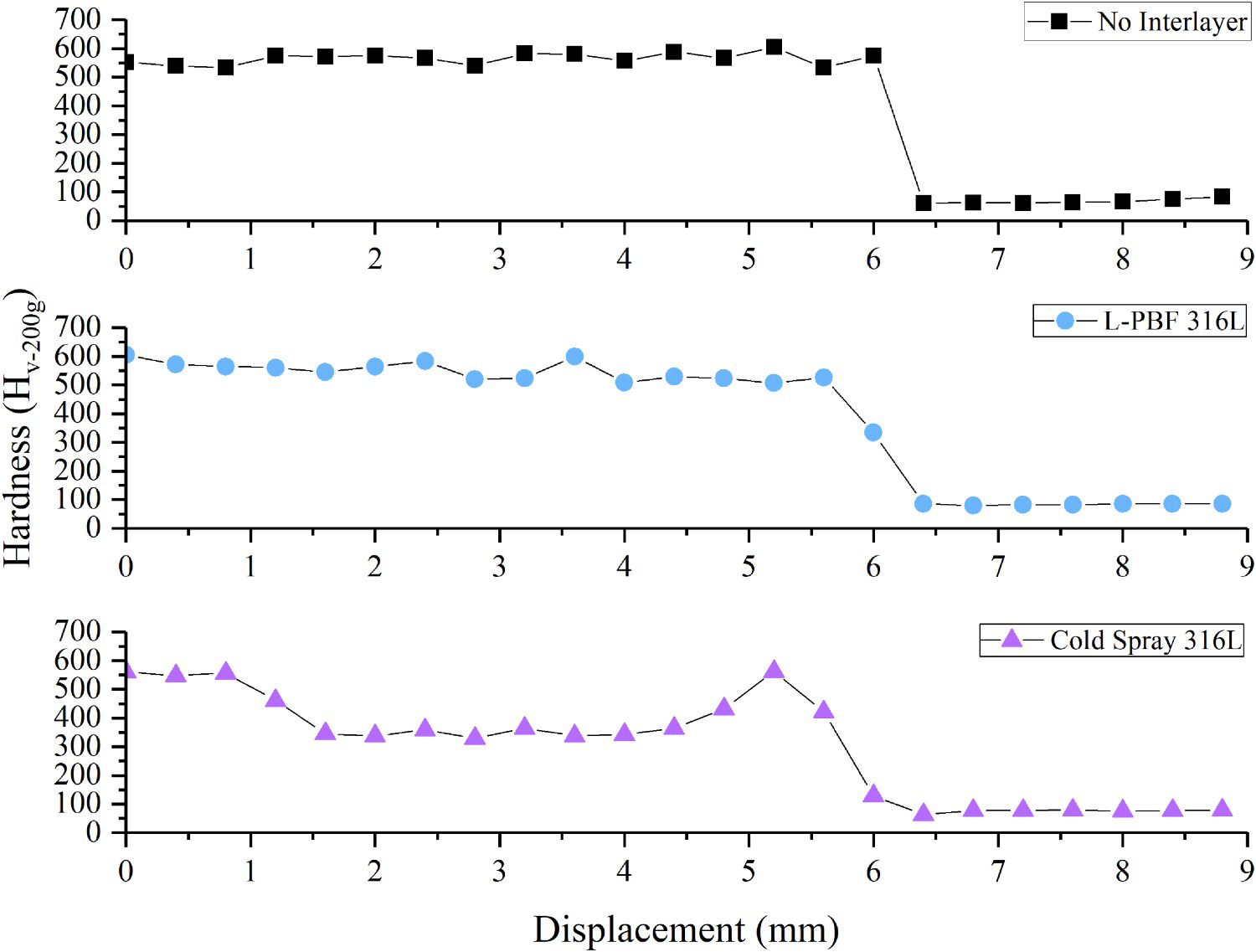
Tensile shear testing
The mechanical properties were assessed. As mentioned, an average value was calculated based on three replicas for each condition, and the error was calculated based on a 95% confidence interval. The no interlayer condition exhibited the poorest joint performance with a peak force and fracture energy of 0.4 kN ± 0.1 and 1.8 J ± 0.1, respectively. The sample with the highest force and fracture energy was the cold spray 316L conditions with 6.4 kN ± 0.3 and .0 J ± 0.4. Notably, the interlayer joints experienced more significant aluminium bonded regions, indicating that the interlayer conditions experienced increased temperatures. The joint efficiency was determined in order to account for variations in aluminium bond area by taking the joint peak force (JPF) in conjunction with the area of the bonded region ( ) to determine the nominal peak tensile stress (
 ). The ultimate tensile strength of the 6022-T4 aluminium was divided by the
  to determine the joint efficiency. Importantly, it is difficult to quantify the rotating stresses acted upon the joint during tensile shear testing, and defects such as porosity were ignored for ease of calculation. Owing to their increased peak force, the interlayer joints were more efficient, 60% and 55% for the L-PBF and cold spray conditions. The least efficient joint was the no interlayer condition with 15%.
The cold spray 316L cross-section of the failure is illustrated in Figure 6. Figure 6(a) shows the aluminium side fracture regions in which the AlSi coating from the PHS steel is retained. There are aluminium areas left from the tensile shear testing, as shown in Figure 6(b). A significant bump can also be observed, protruding inward towards the 316L-aluminium region illustrated in Figure 6(c). Thus a synergetic effect is observed in which aluminium penetrates the 316L interlayer and the PHS bump interlocks the joint while in tensile shear loading to improve that joint performance. In the L-PBF 316L condition, no bump was observed in other conditions, but the printed interlayer did collapse in one direction. The collapse is due to the force and heat generated during the RSW process. As a result, when under tensile load, the printed interlayer will act as a mechanical lock; this was also experienced in the cold spray 316L condition. Likely, the aluminium penetration into the powder interlayers in union with the PHS bump provides a significant performance gain.
Regions of the cold spray 316L interlayer failure: (a) aluminium region, (b) centre of cold spray region, and (c) macrograph of the interlayer and PHS region.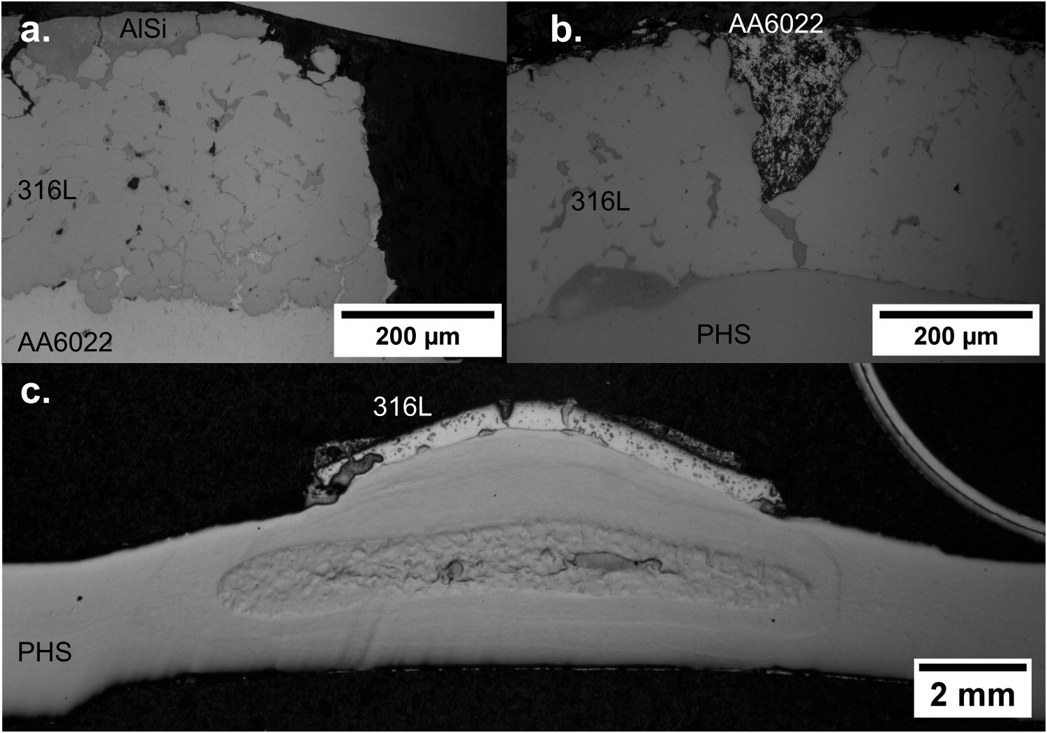
Hatch spacing comparison
The hatch spacing effect on the mechanical performance was also investigated for the additive manufacturing deposition. The aluminium penetration using the 100 µm L-PBF interlayers was then compared to higher hatch spacing conditions. 150 and 200 µm L-PBF conditions were analysed to determine any additional benefit from the aluminium-interlayer penetration. The 150 µm spacing did not collapse, as observed with the 100 µm hatch spacing. The increased hatch spacing distance allowed for more aluminium penetration, which prevented the interlayer from collapsing. When the laser hatch spacing was further increased to 200 µm, no 316L collapse was observed. It can be seen that the larger hatch spacing promoted much further aluminium penetration on the printed 316L interlayer.
Increasing the laser spacing from 100 to 200 µm improved the joint performance by 0.3 kN and 0.7 J. The locking mechanism thus could be further enhanced, as Figure 7 illustrates. The present work did not explore hatch spacing beyond 200 µm. The authors believe that a possible saturation effect is expected as the hatch spacing increases. Such a topic could be explored in future work.
Hatch spacing comparison for the L-PBF 316L interlayer conditions.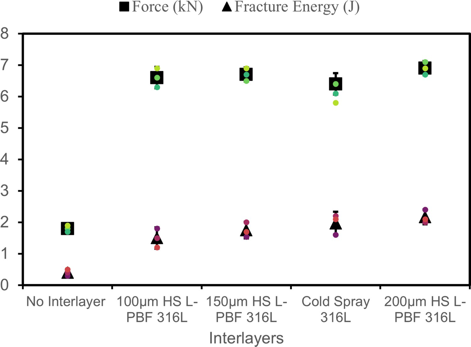
Figure 8 shows the failure of the 316L deposition processes. All the conditions failed in the interfacial failure mode and resulted from the material thickness. Thicker and harder sheets fail in the interfacial failure mode [29,30]. Notably, Figure 8(a) shows a large section of the cold spray 316L region being removed after tensile shear loading further supports the aluminium's interlocking. Figure 8(b) does not exhibit such characteristics but observes aluminium on the 100 µm L-PBF 316L surface after failure. Figure 8(c) shows considerable removal of the L-PBF 316L interlayer due to the aluminium interlocking. The 316L interlayer was partially detached from the PHS surface and bonded to the aluminium. Noticeably, this resulted in increased ductility when comparing the force–displacement curves, and thus is why differences in the fracture energy between the 100, 150, and 200 µm conditions arise.
Failure mode comparison between the cold spray and L-PBF interlayers: (a) cold spray 316L, (b) 100 µm hatch spacing L-PBF 316L, and (c) 200 µm hatch spacing L-PBF 316L.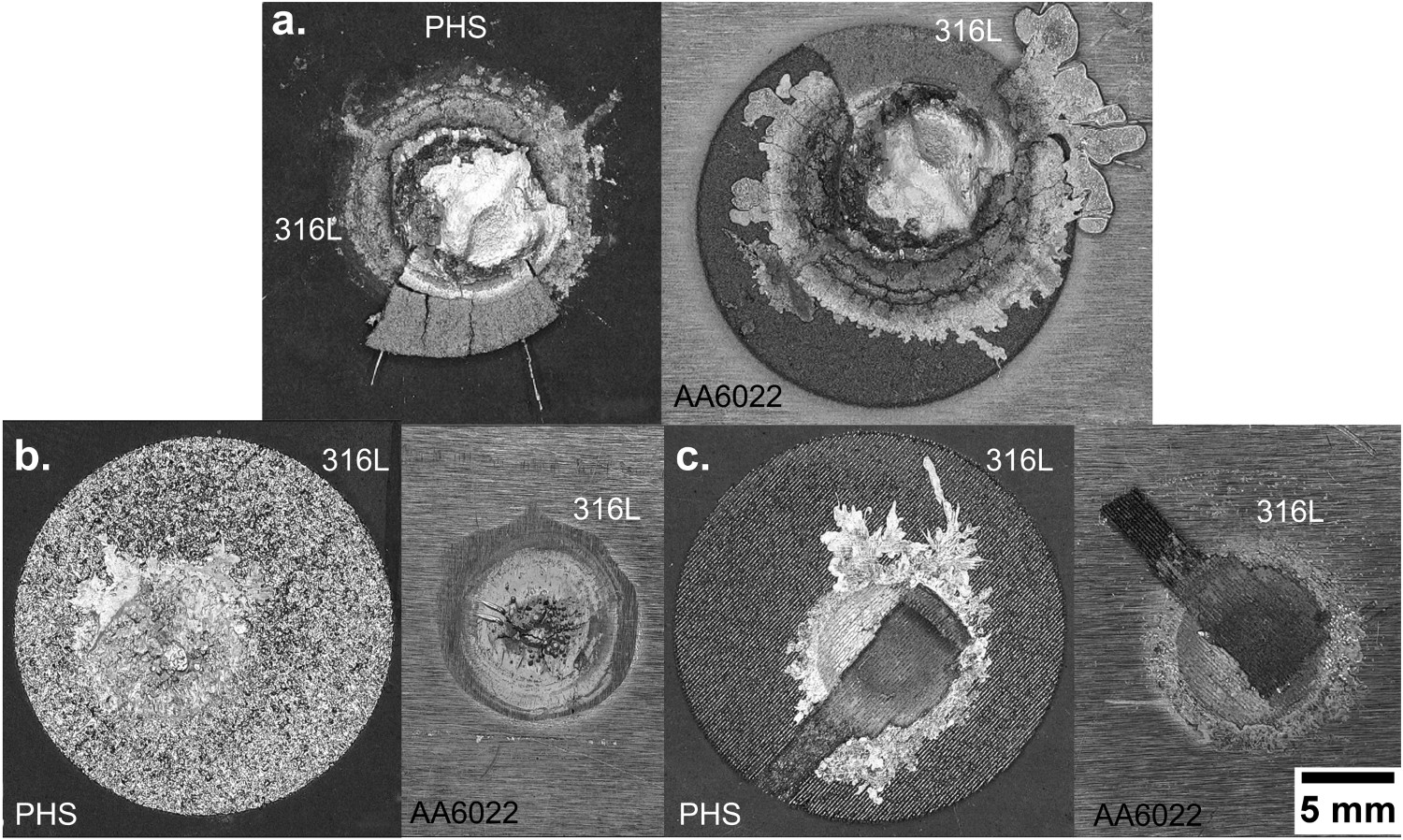
Both interlayer deposition processes exhibited higher force and fracture energy when compared to the no interlayer. However, the cold spray deposited 316L underwent a higher deformation due to the aluminium penetration within the 316L interlayer. As a result, the cold spray process experienced higher ductility upon tensile shear loading that was not evident with the L-PBF 316L interlayer. The cold spray exhibited a larger HAZ indicative of higher temperatures and bonding diameters that helped surpass the L-PBF 316L. Thus, the lower density cold spray interlayer performed better due to this combination of interlayer process parameters, composition, and joule heating.
Conclusions
The mechanical properties of a resistance spot welded PHS and aluminium alloy joint was assessed using a cold spray and laser powder bed fusion 316L metallic interlayer. From this research, the following can be drawn:
The RSW of a stainless steel 316L interlayer successfully improves the peak load and fracture energy absorption compared to the no interlayer conditions due to aluminium penetration within the interlayers. There was no critical difference between the fusion-based L-PBF process and the solid-state deposition technique. Hatch spacing differences influence the peak load and energy absorption due to the mechanical locking between the L-PBF 316L and aluminium upon tensile shear testing. The increase in energy absorption is attributed to the increase in ductility from the force–displacement curve. More significant aluminium bonding was observed in the interlayer joints due to increased heating and microhardness variations resulting from HAZ size. Hardness variations along the cold spray 316L interlayer were observed due to the AlSi coating, which experienced cracking near the base of the interlayer.
Footnotes
Acknowledgements
Special thanks to the Center for Electron Microscopy and Analysis (CEMAS) at The Ohio State University for the SEM equipment used to perform the electron microscopy. The authors also thank colleagues Eric Brizes and Jacque Berkson, undergraduates Luke Kumler of OSU welding engineering. Also, Brock Golesich of VRC Metal System for his expertise in the cold spray deposition process.
Disclosure statement
No potential conflict of interest was reported by the author(s).