
Abstract
The longitudinal residual stresses in the friction stir-welded plates of 5A06 aluminium and pure copper were determined using the contour method. The results revealed the presence of high tensile and compressive residual stresses on the aluminium and copper sides, respectively. The residual stresses were detected on the weld zone as well as the thermo-mechanically affected zone (TMAZ) of the aluminium plate. In contrast, the compressive residual stresses in the copper plate had a much narrower width along the weld line. Peak tensile stresses up to 240 MPa were found in the TMAZ of the aluminium plate.
Introduction
Combination of the excellent thermal and electrical properties of pure copper with the light weight and low cost of aluminium alloys has always been of great interest in power generation, aerospace, automotive and electronics industries [1]. In order to exploit the combined potential of these materials a reliable and viable welding method is needed. Fusion welding of aluminium to copper has proved unsuccessful mainly due to the differences in their physical and chemical properties. For instance, unavoidable formation of hard and brittle intermetallic compounds (IMCs) at the weld zone results in low strength and very low-impact-resistant joints [2-4].
Friction stir welding (FSW), generally regarded as a solid-state process, is one of the most promising solutions for joining dissimilar alloys, e.g. aluminium to copper. Most of previous academic and industrial investigations were aimed at optimising the FSW process parameters, improving microstructures, reducing defects and enhancing mechanical properties of friction stir-welded Al and Cu plates. Previous work clearly proved that the process parameters such as relative position of base materials, tool offset [5, 6], rotational, traverse speeds [7-9] and tilt angle of the rotating tool [10] as well as the material properties [11] all can affect the macrostructure, microstructure and mechanical properties of the Al–Cu joints. The mechanical mixing of Al and Cu during FSW results in composite-like structures which consist of copper-rich particles and intermetallics distributed within the aluminium-based matrix [4, 6, 12-14]. The lamellar structures seen in the friction stir-welded Al and Cu consist of different phases with a swirl pattern [1, 5, 6, 12, 15]. Meanwhile, the unmixed zone of the joint consists of continuous IMCs with a thickness of 0.2–3 µm. The IMCs at the Al/Cu interface have been identified as CuAl2, CuAl and Cu9Al4 [7, 8, 16, 17].
It is reported that thermo-mechanically affected zones (TMAZ) are the weakest parts of most friction stir-welded Al–Cu components, where most of the failures occur due to the formation of large amounts of IMCS [8, 10, 16]. Besides, inadequate interaction between the rotating tool and base material can result in the formation of very undesirable defects such as discontinuities and pores.
The hardness at the nugget zone of a dissimilar Al–Cu FSW is normally higher than those of the base materials again due to the formation of IMCs and severe strain-hardening. It is also reported that the higher the heat input the higher the IMC content, hence the higher the hardness [11, 12, 18].
Residual stresses can drastically compromise the structural integrity, performance and lifetime of welded components. Friction stir welding is associated with a substantial amount of plastic deformation in the materials being joined; hence very high residual stresses are expected in the weld zone which contains severely deformed dissimilar materials with very different Young's moduli. Reports on the residual stresses developed in similar and dissimilar FSW joints are scant and most of previous work concerns Al-to-Al joints. Regardless of the type of alloy, the longitudinal stresses were of main interest in this and previous work since they are substantially higher than those found in the traverse direction [19, 20].
The longitudinal residual stresses normally have an M-shape profile with peak values in the HAZ/TMAZ [19-22]. However, there are some contradictory reports; e.g. Liu and Yi [23] showed that the residual stresses profile in the 8 and 4 mm thick FSW AA6061-T6 plates did not have an M-shape profile. They also measured up to 168 MPa residual stresses close to the edge of the rotating tool shoulder on the advancing side. Such a high level of residual stress is about 60% of the yield strength of parent AA6061-T6 alloy at the room temperature, hence can substantially compromise the joint performance under the service condition. Carlone and Palazzo [24] measured the tensile residual stresses in the weld line of a friction stir-welded AA2024-T3 butt joint using the contour method. The tensile stresses on the weld line were balanced by some compressive stresses on the both sides of the weld. Two peak tensile stresses were detected in the advancing and retreating sides at a distance equal to the radius of the shoulder from the centre line. The maximum residual stress on the advancing side was slightly higher than on the retreating side, i.e. 145 and 125 Mpa, respectively. In contrast, Prime et al. reported very low residual stresses in dissimilar friction stir welds between 25.4 mm thick aluminium plates of 7050-T7451 and 2024-T351 [25]. Their results confirmed the presence of residual stress with an M-shape profile and peak stresses of 43 MPa which are less than 20% of the base material yield strength.
To date, no report was found on measuring or analysing the residual stresses in frictions stir-welded aluminium and copper plates. In this work, the residual stresses generated in friction stir-welded Al and Cu plates were measured by the contour method and the outcome was used to map the stress distribution on a plane normal to the weld line, i.e. cross weld direction.
Experimental
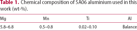
Chemical composition of 5A06 aluminium used in this work (wt-%).
The rotating tool was made of W360 steel with a 15 mm diameter concave shoulder and a 1.9 mm long/5 mm diameter cylindrical probe. The probe was inserted in the aluminium plate with an offset of 0.5 mm. The aluminium alloy was positioned on the advancing side of the rotating tool leaving the copper on the retreating side. Rotational speed of 1000 rev min−1 and traverse speed of 40 mm min−1 were used in all welding trials. The plunged depth of the tool shoulder was 0.15 mm and the pin was tilted 2.5° throughout the welding cycle. Figure 1 shows the welding setup used in this work.
Set-up used for friction stir welding of aluminium and copper plates. Bonded sample was cut across the bond-line using wire EDM to produce the measurement planes needed for residual stress measurement by the contour method.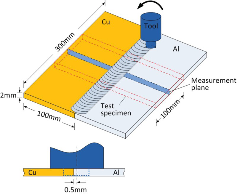
Contour method, which was invented in 2001, is an attractive technique for determining residual stresses in the engineering components [26]. The method relies on acquisition and processing of a very large number of data. The contour samples were prepared by cutting each pair of the welded plates in the middle and normal to the welding direction (see Figure 1). The cutting of contour samples must be carried out using Wire Electrical Discharge Machining (EDM) to prevent any plastic deformation [27]. The specimens in this work were cut with an EDM machine using a 0.3 mm diameter brass-based wire at a constant speed of 1.6 mm min−1. The specimens were submerged in the temperature-controlled deionised water during the cutting process. All cuts started on the Al side of the specimen and it took about 120 min to finish each cut. Figure 2 shows one of the samples in the clamped position and after EDM cut across its bond-line.
Frictions stir-welded Al and Cu plates were cut across the bond-line by wire EDM method. Arrow shows the cutting direction.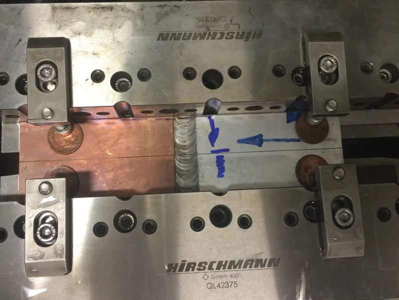
The two halves of each specimen were kept at a temperature-controlled room for at least 1 h before measuring their surface profile. The surface profiles were measured using a coordinate measuring machine (CMM) equipped with a laser scanner. It took 70 min to collect about 625,000 data points from each scanned surface with a spacing of 0.025 mm in both X and Y directions. The actual scanning setup is shown in Figure 3.
Laser scanner used for surface profiling of friction stir-welded Al and Cu samples.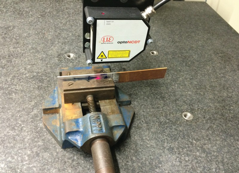
The displacement data (surface profile), collected from two halves of each sample, were aligned and averaged point by point to remove the effects of shear stresses and cutting artefact. Then the data were ‘cleaned’ by removing the noises and outliers, which otherwise could result in errors. The data smoothing was carried out using the cubic spline fitting method, which is a common practice in the contour method. The surface profiles of a sample before and after smoothing are shown in Figure 4. The smoothened data were used as the boundary conditions in the subsequent finite element (FE) analysis.
Surface profile of an Al–Cu sample before (top) and after smoothing (bottom).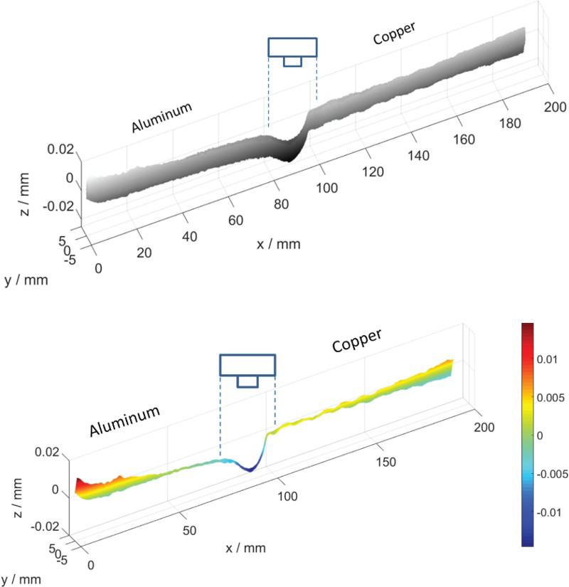
A 3D linear elastic FE model of half specimen was created. The FE model of a test specimen is shown in Figure 5 in which the measured displacement data were used as the boundary conditions in order to calculate the residual stresses normal to the cut surface [27, 28].
Finite element model of the surface contour of friction stir-welded Al–Cu plates (magnified by factor of 300).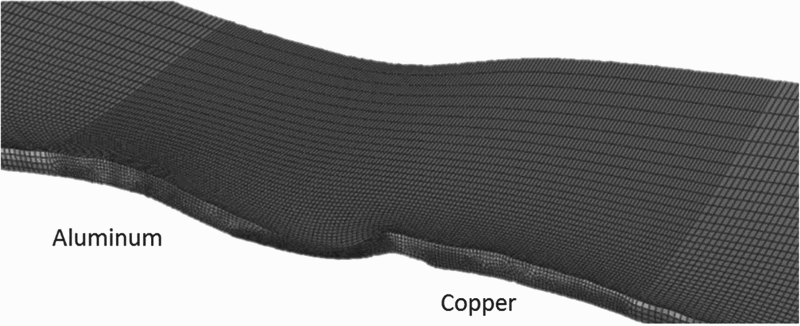
Young's modulus of the weld region needs to be determined as precisely as possible, since it has a direct influence on the accuracy of calculated residual stresses. Figure 6 shows the microstructure of an Al–Cu joint with a relatively clear border between the two materials. The clear border allowed using the Young's modulus of parent aluminium and copper on the corresponding areas. The contour method is limited to 2D measurement of residual stresses, i.e. the stresses normal to the cut surface. However, 3D measurements of residual stresses using the contour method should be possible by successively removing thin layers and repeating the entire process i.e. depth profiling. Admittedly, this assumption that the weld zone consists of two distinctive areas is far from reality and more appropriate approaches need to be developed in the future work.
Microstructure of friction stir-welded Al–Cu plates in low (top) and high (bottom) magnifications.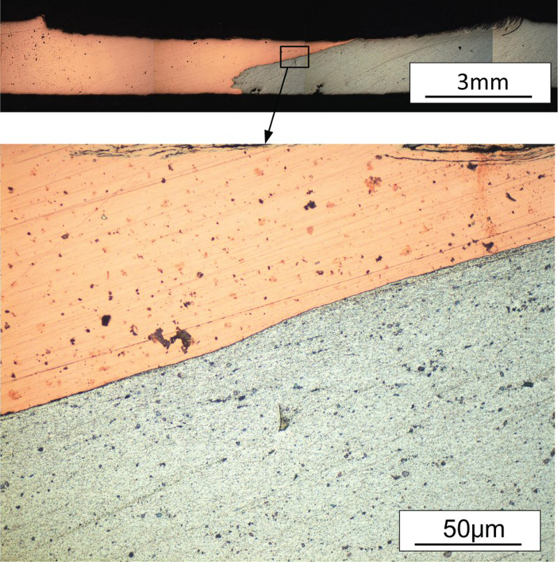
For the FE analysis, the Young's moduli of 67 and 117 GPa and Poisson's ratios of 0.33 and 0.36 were used for 5A06 aluminium and T2M pure copper, respectively. The elastic properties of both materials were assumed to be isotropic.
Results and discussion
The residual stresses distribution map, generated by the contour method, is shown in Figure 7. It is evident that the magnitude and distribution of residual stresses are significantly different on the aluminium and copper sides. The longitudinal stresses (acting normal to the cut surface) on the aluminium and copper sides are tensile and compressive, respectively. Also, the width of the stressed zone in Al is far wider than that in the copper. This is due to aluminium having a lower Young's modulus than copper. The tensile stresses on the aluminium side are extended across the entire weld region and TMAZ, while the compressive stresses in copper are located near the joint interface. It was interesting to see that the region with residual tensile stress (Al side) is wider than the tool shoulder. The peak tensile stress was found near the TMAZ on the aluminium side, which was the advancing side of the rotating tool. The location of the peak tensile stress observed in this work is consistent with those of the previous work conducted on similar/dissimilar aluminium friction stir welds [25, 29-31]. The maximum compressive stress on the copper side was very close to the weld centre line.
Map of longitudinal residual stresses on friction stir-welded Al–Cu plates generated by the contour method.
Very high amounts of tensile stresses were observed in the aluminium TMAZ as well as the joint interface. The residual stresses in dissimilar joints are due to having different coefficient of thermal expansions. When a dissimilar weldment cools down, the material with a higher coefficient of thermal expansion shrinks faster resulting in the build up of tensile residual stresses and vice versa for the other material [32]. The linear coefficient of thermal expansion (CTE) of aluminium is about 30% larger than that of copper, i.e. 23.2 × 10⁻⁶ and 17.5 × 10⁻⁶ K−1, respectively. This is consistent with the results of contour measurement, which revealed the presence of tensile stresses on aluminium side and compressive stresses on copper side, as shown in Figure 7.
From a different perspective, the thermal conductivity of copper is higher than that of aluminium, i.e. 401 and 237 W m−1 K−1, respectively. Therefore, the heat generated during the welding process dissipates faster in copper than in aluminium. In short, copper is a stiffer metal than aluminium and tends to shrink less than aluminium due to having lower CTE and higher thermal conductivity. These differences in the physical and mechanical properties of copper and aluminium led to having a much narrower stressed zone on the copper side near the joint interface – see Figure 7.
Figure 8 shows the outcome of two line-scans, which were carried out on the contour map at about 0.5 mm from the top and bottom surfaces. The peak tensile stresses in both top and bottom surfaces of the Al are about 240 MPa. In contrast, the maximum compressive stresses in the copper are 350 and 270 MPa close to the top and bottom surfaces, respectively. Although the exact source of such variation remains to be investigated, it is reasonable to ‘speculate’ that the soft Al has already reached its maximum containable level of residual stress on both surfaces. The yield and ultimate strengths of 5A06 aluminium are 171 and 345 MPa, respectively; while those of T2M copper are 62 and 227 MPa. Therefore, design engineers would find having such high tensile residual stresses quite alarming. Optimisation of FSW process parameters can be considered to mitigate the residual stresses.
Residual stresses measured by line scanning 0.5 mm beneath the top and bottom surfaces.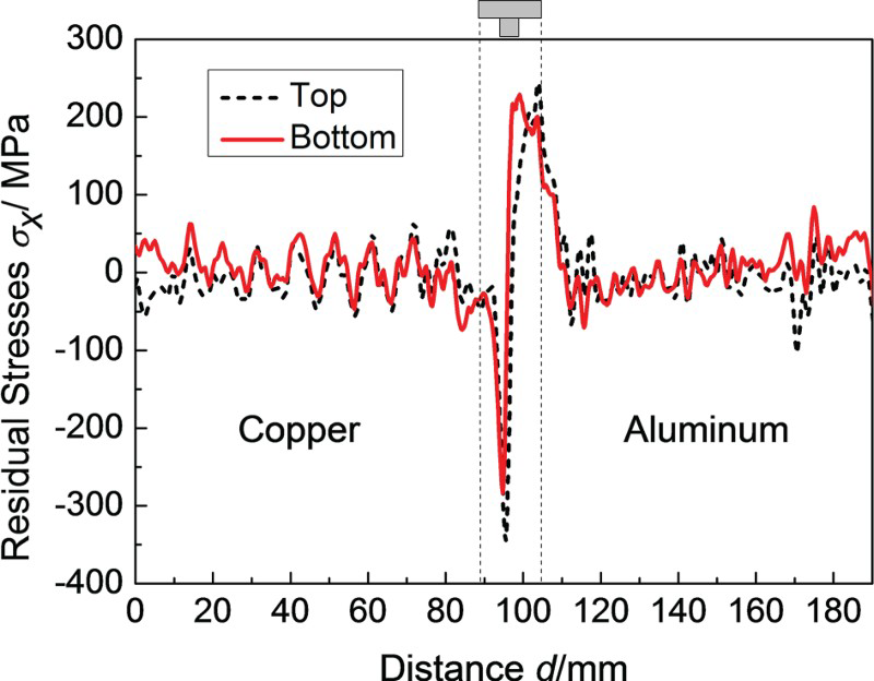
Extraction of narrow coupons may affect the residual stress in the centre of a weldment. However, previous work showed that the maximum remaining stress at the centre of a narrow coupon is about 95% of that of an infinitely wide sample if the coupon is twice wider than the width of the stress-affected zone [33]. In this work, the sample coupons were five times wider than the stress-affected zone, i.e. 20 mm wavelength of residual stress shown in Figure 8 compared to 100 mm wide coupons. Therefore, any relaxation in the residual stress, due to using a 100 mm wide coupon, would be negligible compared to other experimental errors.
Conclusions
Longitudinal residual stresses in the friction stir-welded aluminium and copper plates were analysed by the contour method. The outcomes of this work are as follows.
The longitudinal stresses in the aluminium and copper plates proved to be tensile and compressive, respectively. The tensile stresses on the aluminium side is extended throughout the entire weld region and TMAZ, whereas the compressive stresses in the copper plate had much narrower width along the joint interface. The maximum tensile stress of 240 MPa was detected near the TMAZ in the aluminium plate. The residual stresses in friction stir-welded Al–Cu plates were too high to achieve reliable and structurally sound bonds.
Footnotes
Acknowledgements
Authors would like to thank Peter Ledgard for conducting the EDM cuts; Dr Jeferson Oliveira for conducting the profile measurement and Dr Sanjooram Paddea for his help with the FE analysis.
Disclosure statement
No potential conflict of interest was reported by the authors.