
Abstract
Piezoelectric materials can directly transduce electrical and mechanical energy, making them attractive for applications such as sensors, actuators and energy harvesting devices. While often associated with ceramic materials, piezoelectric behaviour is also observed in many polymers. The flexibility, ease of processing and biocompatibility of piezoelectric polymers mean that they are often preferable for certain applications, despite their lower piezoelectric coefficients. This review will cover some theoretical and practical concepts of piezoelectricity in polymers, such as the symmetry requirements, the underlying mechanism and the necessary materials processing. A brief review of the applications of piezoelectric polymers is also presented. One of the main motivations of this review is to discuss the challenges and open questions in the field in an effort to highlight potential future research directions.
Introduction
Piezoelectric materials can directly transduce electrical and mechanical energy, making them attractive for use in sensors, actuators, energy harvesting (EH) devices as well as numerous other technologies. The piezoelectric effect is often associated with ceramic materials, yet piezoelectric behaviour is also observed in many polymers [1]. The flexibility, ease of processing and biocompatibility of piezoelectric polymers mean that they are often preferable for certain applications, despite typically having lower piezoelectric coefficients [2] than their ceramic counterparts. There are a number of polymer families which display piezoelectric effects. Beyond the well-known ferroelectric polymer poly(vinylidene fluoride) [3], piezoelectric behaviour is also observed in some polyureas [4], polyamides [5], polypeptides [6] and polyesters [7].
There are numerous recent reviews on the topic of piezoelectric polymers [1,2,8–16] which provide comprehensive lists of the reported piezoelectric polymers and their applications. Rather than repeating what has already been well covered, this review will instead focus on some fundamental concepts of piezoelectricity in polymers (both theoretical and practical) using typical materials as examples to provide context.
The concept of symmetry with respect to piezoelectricity will be discussed and shown to be an important tool with respect to the phenomenon in polymers. A brief discussion of the mechanism of piezoelectricity in polymers is presented as well as practical information on the processing, optimisation and characterisation of piezoelectric polymers. Finally, a short review of some applications of piezoelectric polymers is given.
One of the main motivations of this review is to highlight open questions in this field and address the areas where there are conflicting theories and ideas. By making these critical issues explicit, it is hoped that researchers will be in a better position to resolve the challenges with these materials, improve current understanding and advance the technological state of the art.
A brief history of piezoelectricity in polymers
Piezoelectricity was first identified in inorganic crystals by Jacques and Pierre Curie in 1880 [17]. Today, the phenomenon is still associated with ceramic materials and the vast majority of piezoelectric materials currently used in real-world applications are inorganic. Ceramic piezoelectric materials can have large piezoelectric coefficients, up to 500 pC N−1 in the case of lead zirconium titanate (PZT) [18]. However, the composition and mechanical properties of ceramics are not suitable for all applications. Fortunately, there is nothing fundamental that restricts piezoelectricity to ceramic materials – indeed, piezoelectricity is also observed in some polymeric materials. Generally, the piezoelectric coefficients are smaller, but the materials are more compliant and more straightforward to process. Piezoelectric polymers are not a replacement for piezoelectric ceramics, rather the two groups complement each other.
Interestingly, the first non-ceramic materials reported to show piezoelectricity were biomaterials. Piezoelectric effects in wood were first reported around 1950 [19], closely followed by evidence of the phenomenon in collagenous tissues such as bone and tendon [20,21] and even DNA [22]. Much of this early work was carried out by Eiichi Fukada, a pioneer in the field of polymeric and biological piezoelectricity [23].
Initially, these findings drew little attention beyond the biomaterials community. This is perhaps understandable, given that the largest of the measured piezoelectric constants were typically 1/20th that of quartz, the most well-characterised piezoelectric material at that time [24].
Interest in piezoelectric polymers from the wider scientific community began in 1969 when Heiji Kawai discovered piezoelectric effects in the synthetic polymer poly(vinylidene fluoride) (PVDF) [25]. The piezoelectric coefficients were at least an order of magnitude larger than anything previously observed in polymers. Moreover, the symmetry of the piezoelectric response was very different from that previously recorded. Confirmation of pyroelectric [26] and ferroelectric behaviour [27,28] in PVDF soon followed, piquing interest in piezoelectric polymers for applications in many disciplines. In the years that followed, piezoelectric behaviour was identified in several other polymer families [1,29] and now piezoelectric polymers are the centre of intense scientific research for applications in EH, wearable technology and biomedical devices.
Piezoelectric theory
The piezoelectric effect describes the transduction of electrical and mechanical energy in a material. More thoroughly, it is the linear coupling between the stress state of a material and its electrical polarisation. The effect is inherently reversible; a polarisation can develop as a result of an applied stress, or a strain can occur as a result of an applied electric field. These are known as the direct and indirect piezoelectric effects, respectively. The latter is sometimes also referred to as the inverse piezoelectric effect.
A mathematical description of piezoelectricity
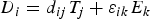
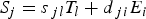
The effect is described in terms of the electric displacement D, electric field strength E, stress T and strain S of the material through the constitutive strain–charge equations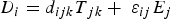
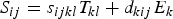
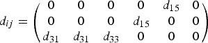
The condition of static equilibrium means that there are only six independent elements of Tjk
, since A schematic representation of the directions referred to in Voigt notation.
Definitions of the piezoelectric coefficients, including their experimental relevance and units.
[D], direct effect; [I], indirect effect.
The first column represents the direct effect – an electrical response as a result of a mechanical stimulus. The second column refers to the indirect effect – a mechanical response to an electrical stimulus. Each coefficient is defined with respect to certain constraints, giving each coefficient a unique experimental relevance, as also shown in Table 1. Possible units of each are also shown, although there are other dimensionally equivalent combinations. For example, dij can be expressed in units of C N−1 or m V−1.
Despite these obvious distinctions, there is no universal convention regarding the individual names of these coefficients, any one of them may be referred to as a ‘piezoelectric coefficient’. The coefficient dij is most commonly used when discussing and comparing the piezoelectric properties of materials and will be used throughout this review, but others may be more appropriate depending on the exact application. Components of dij for j = 1 → 3 are considered as ‘normal’ modes, in that they couple an electric field to a normal (tensile or compressive) strain and vice versa. Components of dij for j = 4 → 6 are shear modes since they relate to shear strains in the material. The same conventions are also true for all the other piezoelectric coefficients.
Symmetry in polymers and its implications for piezoelectricity
Piezoelectricity was first described in crystalline materials such as Rochelle salt (potassium sodium tartrate) and quartz. As a result, qualitative descriptions are conventionally presented in terms of a regular crystal lattice: piezoelectricity arises due to the displacement of ions and atoms within non-centrosymmetric unit cells. This intuitive description works well for materials such as ceramics which possess a regular crystal structure.
Polymers, however, consist of a network of long molecules. Regions of these polymer chains can form small crystallites; however, these regions are surrounded by the amorphous matrix of the remaining polymer chains. Given the differences between the internal structure of ceramic and polymeric materials, it is not obvious if the same intuitive model of piezoelectricity can be applied to polymers. The topic of the exact mechanism of piezoelectricity in polymers will be returned to in a later section. First, we will discuss the relevance of symmetry with respect to piezoelectricity, and how this is useful when considering piezoelectric polymers.
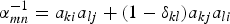
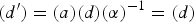
The requirement for non-centrosymmetry still applies to piezoelectric polymers. To explain why, it is necessary to consider Neumann’s principle. This states that the symmetry of a material must be represented in the symmetry of its properties. This statement is true for all material properties and is especially useful when considering the piezoelectric properties of a material. Neumann’s principle can also be framed analytically. Following the example of Newnham [30], the matrix representation of the piezoelectric tensor can be transformed between coordinate systems using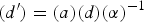


Crystallisation of the polymer might appear to resolve this issue. Of the 32 crystallographic point groups, 21 do not possess inversion symmetry and many polymers can crystallise into one or more of these non-centrosymmetric point groups. However, as mentioned before, bulk polymers are only ever semi-crystalline. Multiple crystalline regions will grow within the amorphous matrix and on average, these crystallites will exhibit a random orientation distribution. In much the same way as a random network of polymer chains is isotropic, a random distribution of crystallites is also isotropic. Some other processing is therefore necessary to generate some anisotropy within the material.
Drawing is a common processing method used for polymers and describes the process of stretching a polymer to several times its original length. During this process, polymer chains in the amorphous fraction of the material align with the drawing direction to accommodate the extension. This reorganisation also realigns any crystalline regions embedded within the amorphous matrix. The resulting polymer is radially symmetrical about this drawing axis – that is, its structure is invariant under an arbitrary rotation about the drawing axis. By Neumann’s principle, the piezoelectric matrix must also be invariant under this transformation.
The matrix representing an arbitrary rotation by angle θ about the ‘3’ axis is given by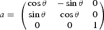
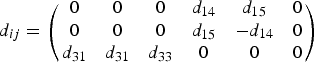
One way to include the ambiguity of the ‘3’ axis is to introduce a mirror plane in the 1–2 plane. In this instance
The only polymers that satisfy these criteria are those which possess handedness, i.e. those with a helical conformation of the polymer chain. This is often a consequence of a chiral monomer unit and is frequently found in biologically derived polymers. The helical twist breaks the mirror plane but is still invariant with respect to a 180° rotation perpendicular to its axis.
Another processing method which can be used to introduce anisotropy is electrical poling. During this process, a large electric field is applied to the material to align dipoles within the structure. Note that, in general, this is only possible in piezoelectric materials which are also ferroelectric, since only in these materials is the polarisation spontaneous and reversible.
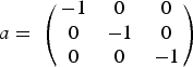
The electric field used to pole a material is radially symmetric, so we can repurpose the matrix from Equation (14), this time assigning the ‘3’ direction to the poling direction rather than a drawing direction. The electric field is polar, so there is no need to introduce a mirror plane or rotation axis, but it is not ‘handed’. This symmetry element must therefore be removed from the matrix in Equation (14). Introducing a mirror plane in the 1–3 plane removes any handedness. The corresponding transformation matrix is
The important conclusion from this discussion is that removing the centre of symmetry from any given polymer sample – be it amorphous or semi-crystalline – requires some degree of processing. This processing will restrict the symmetry of the final material. The combination of the processing method (i.e. drawing, poling) and any inherent symmetry elements of the polymer (i.e. handedness) will determine the final symmetry group of the sample. Only some combinations of these symmetry elements permit piezoelectric behaviour. Furthermore, only a subset of the 18 possible piezoelectric coefficients will be permitted in each case.
Piezoelectricity in polymers
As mentioned previously, piezoelectric behaviour is a common property of several polymer families including fluoropolymers, polyureas, polyamides, polypeptides, polysaccharides and polyesters. A large number of biopolymers – materials such as collagen [20], cellulose [24] and silk [32] – also possess piezoelectric behaviour. The prevalence of piezoelectricity in biological materials led to suggestions that piezoelectricity was a fundamental property of biological tissue [21] and that the piezoelectric effect was a critical aspect of many biological processes [33,34]. Subsequent observations have shown the piezoelectricity is likely only a part of these complex processes [35,36]. Nonetheless, there is still a huge amount of research into the use of piezoelectric materials, natural or otherwise, in biological contexts [37–44] – this is discussed further in the section regarding applications of piezoelectric materials.
In this review, we will explain some theoretical and practical concepts of piezoelectricity in polymers by using some typical materials as examples to provide context. Three polymers in particular will be frequently used as case studies: PVDF and co-polymers [45], odd-numbered Nylons [46] and poly- Three commonly used piezoelectric polymers for practical applications: P(VDF-TrFE), odd-numbered Nylons and PLLA. The sample preparation required in order for each material to exhibit piezoelectricity is also shown, where D
R is the draw ratio, T is the drawing temperature and E is the electric field strength of the poling field. *The full piezoelectric tensor of odd-numbered Nylons is scarcely reported.. Given the sample preparation used, the symmetry is assumed to be mm2.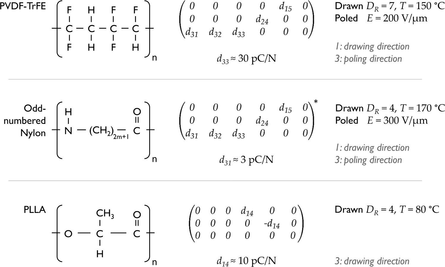
While some of these polymers exhibit multiple independent piezoelectric coefficients, researchers working on each polymer tend to discuss only one coefficient. Typical values for these coefficients are given in Figure 2. Some general sample preparation conditions are also presented, although as we will see later, this is not always straightforward. The axis convention for each polymer is also shown, highlighting how this is not always the same for each polymer. In P(VDF-TrFE), for example, the ‘3’ axis is assigned to the poling direction and, if the polymer has been drawn, the ‘1’ axis is used as the drawing direction by convention. In contrast, for PLLA, the ‘3’ axis is used for the drawing direction and there is no poling direction.
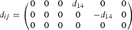
It is worthwhile to note that while P(VDF-TrFE) and odd-numbered Nylon exhibit both normal and shear modes of piezoelectricity, PLLA only exhibits shear modes. Furthermore, P(VDF-TrFE) and Nylon require poling before displaying piezoelectric effects, while PLLA does not. This can be understood by considering the symmetry of each polymer, as discussed in the previous section regarding symmetry and its implications for piezoelectricity. The PLLA molecule exhibits a helical conformation due to its chirality [50]. This helical symmetry of PLLA means that simply aligning the polymer chains is sufficient to remove any centre of symmetry and permit piezoelectricity. The symmetry elements involved, however, exclude all but the d14 and d25 (= − d14 ) shear coefficients. This also explains why piezoelectricity is observed in naturally in biological materials – after all, these materials are neither drawn nor electrically poled in the body. The chiral nature of these biological molecules means that simply the alignment that occurs between molecules during tissue growth is sufficient to allow the material to express piezoelectricity.
P(VDF-TrFE) and Nylons exhibit planar conformations of the polymer chain, and therefore simply aligning the polymer chains is insufficient to allow piezoelectricity. Instead, these polymers can be subjected to an electric field (symmetry ∞m) to remove the centre of symmetry. Note that this is only possible because both P(VDF-TrFE) and odd-numbered Nylons can exhibit ferroelectric behaviour, and thus, in the solid state, the material polarisation can be manipulated by the application of a suitably large electric field. The final symmetry of these systems permits both normal and shear piezoelectric coefficients.
It is worthwhile to note that several piezoelectric biopolymers, such as diphenylalanine (FF) [6] and collagen [51], can form nano- and micro structures such as bundles, rods and tubes via self-assembly. These structures are nominally single crystals, and therefore an individual structure is not subject to the symmetry constraints of processing as previously discussed. However, as soon as two or more of these structures are part of the same piezoelectric device, the same symmetry arguments apply.
The piezoelectric mechanism in polymers
In the earlier discussion regarding symmetry and piezoelectricity, the allowed piezoelectric matrices were derived using symmetry arguments. This shows which components of dij are permitted by the symmetry, but does not indicate why some polymers are piezoelectric while others are not. A convincing and universal theory describing piezoelectricity in polymers does not currently exist. Most likely this is because there is no universal theory – the piezoelectric mechanism in Nylon-11 is almost certainly different to that in PVDF, which is again different to that in PLLA.
Fundamentally, the effect arises due to electrical charges within the material, and therefore, it is reasonable to assume that some degree of polarity in the polymer molecule is required, perhaps from electronegative elements such as fluorine and oxygen. Yet, there are numerous polymers that contain these elements, which can be processed to possess the correct symmetry, which still do not exhibit the piezoelectric effect. The key to understanding the origins of the phenomenon is likely determining how these charges are coupled, through the polymer chains and the polymer structure, to the external stimulus – be it mechanical or electrical. This is a formidable task. Polymer systems are hugely complicated, in part due to their semi-crystalline structure. Indeed, it is worth discussing the role of crystallinity in the piezoelectric behaviour of polymers.
There are conflicting theories regarding the role of crystallinity in the piezoelectric behaviour of polymers. The dimensional model is a popular theory describing the piezoelectric effect in PVDF and its co-polymers [52,53]. In this model, the molecular dipoles associated with the polymer chains are rigid and unchanged by an externally applied stress. Deforming the material simply moves the surface electrodes within the field generated by these rigid molecular dipoles, resulting in changes in the charge accumulated on each electrode.
Since the dipoles are assumed to be rigid and fixed, the deformation is accommodated by the amorphous matrix, and hence the piezoelectric effect can be attributed to the amorphous fraction of the material. Indeed, in the dimensional model, there is no requirement for the material to contain any crystalline regions, provided the material contains some dipoles and they share a common alignment (a point we will return to when discussing electrical poling).
On the other hand, some computational models of the PVDF crystal structure claim that the piezoelectric effect can be completely explained by only considering changes in the lattice constants of the unit cell [54]. That is, the crystalline regions are solely responsible for the observed piezoelectric effects and the amorphous matrix is no more than just a matrix. In computational modelling of piezoelectric polymers, the amorphous fraction is often disregarded entirely [55].
Most likely, the truth lies somewhere in between these two limiting cases. Furthermore, it is probably the case that the relative contributions of amorphous and crystalline components are different for each polymer system.
Careful experimental work by Katsouras et al. [56] indicates that for the case of P(VDF-TrFE), both the amorphous and crystalline regions contribute to the piezoelectric effects observed macroscopically. The influence of the amorphous fraction was actually initially suggested by Eiichi Fukada. Early work on some piezoelectric biopolymers including poly-β-hydroxybutyrate (PHB) blends and PLLA revealed that the piezoelectric properties of these polymers display distinct relaxation around the glass transition temperature (T g) [57–59] – even after changes in mechanical and dielectric properties around T g were accounted for. The glass transition is a property of amorphous polymer chains only, therefore the fact that dij is sensitive to this transition indicates that amorphous polymer chains are at least in part responsible for the piezoelectric effect in these polymers.
In these instances, Fukada and Ando argue that in order for these amorphous regions to contribute to the piezoelectric effect, they must display some degree of molecular alignment. Their experimental evidence shows that removing these aligned amorphous regions also removes the relaxational behaviour in the piezoelectric properties [59]. Even though the intermolecular spacing is non-uniform in these aligned amorphous regions, collectively, they may possess the correct symmetry to display piezoelectricity.
The effect of processing on piezoelectric properties of polymers
The properties of any polymer are strongly dependent on its processing history. The same is true of piezoelectric polymers, and indeed in most instances, proper processing is mandatory in order for any piezoelectric behaviour to be observed. When reviewing the literature on the preparation of piezoelectric polymers, three recurring processes are apparent: annealing (or heat treatment), drawing (stretching) and poling (applying an electric field). Each of these processes will be discussed in the following sections, but it is important to keep in mind that they are all somewhat interconnected and that performing one procedure can have an impact on the outcome of another.
Annealing
Heat treatment, or ‘annealing’, can be used to increase the crystalline fraction of a polymer, as shown schematically in Figure 3(a). As discussed in the section concerning the piezoelectric mechanism in polymers, there are conflicting ideas surrounding the relative importance of the amorphous and crystalline fractions towards a polymers’ piezoelectric properties. Nonetheless, annealing is a commonly used method to enhance the electromechanical properties of some piezoelectric polymers. (a) A schematic representation of polymer crystallisation as a result of annealing. Note how that even after crystallisation, the polymer remains isotropic and hence crystallisation in itself is often not sufficient to remove a centre of symmetry. (b) The influence of polymer crystalline fraction on the piezoelectric coefficient of PLLA. Data reproduced with permission from reference [60] . (c) The influence of annealing temperature on the piezoelectric properties of Nylon-11 and Nylon-7. In this instance, annealing has a negative impact, reducing the piezoelectric coefficient. Data reproduced with permission from reference [61] .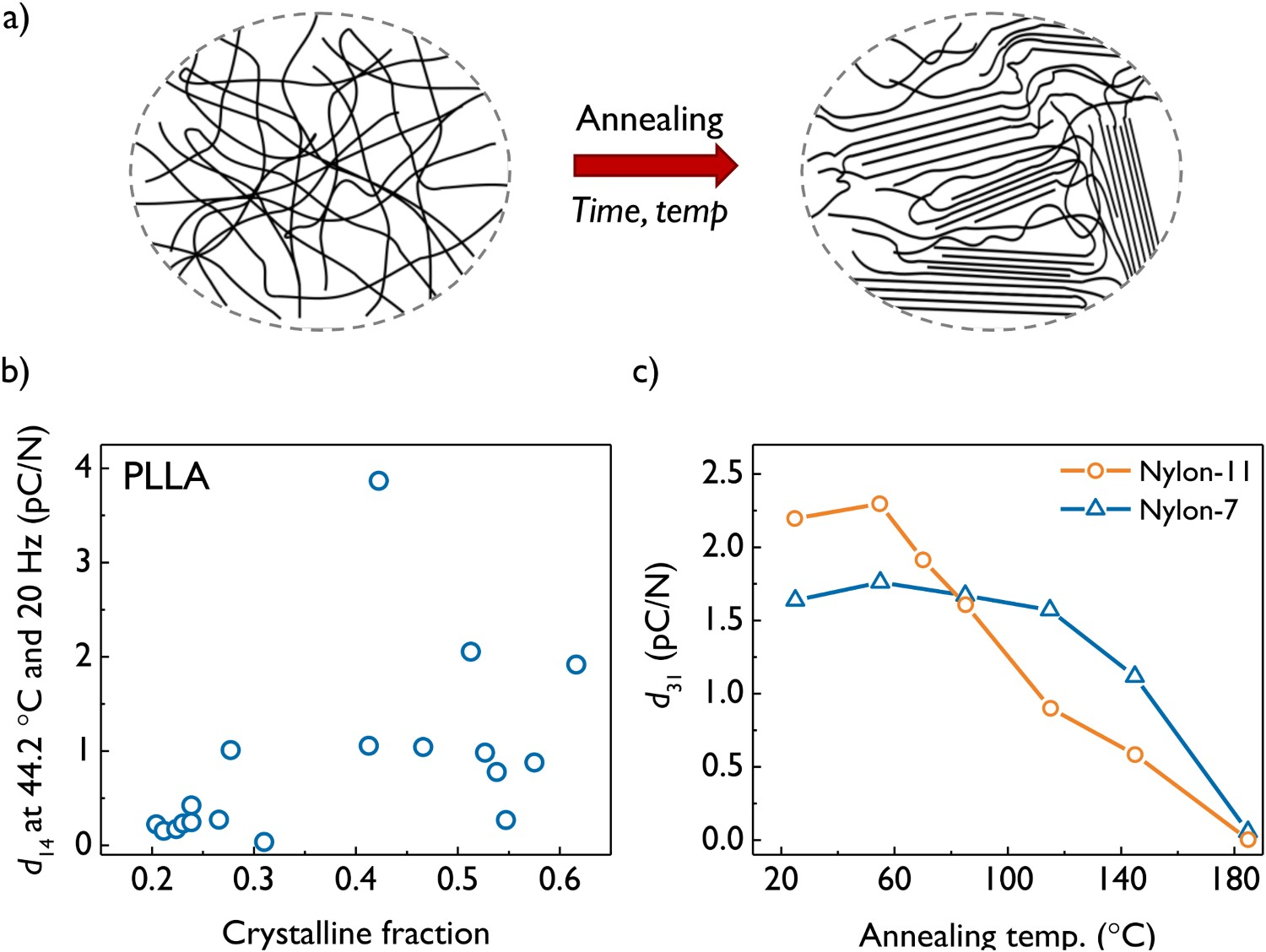
There are several reports that investigate the influence of annealing on the ferroelectric and piezoelectric properties of P(VDF-TrFE) [62–64]. An annealing step can also be found as part of the material preparation in most reports regarding the piezo-/ferroelectric applications of PVDF and co-polymers. Annealing temperatures are typically around 140°C for a period of minutes to hours, although this is likely to be dependent on the exact composition of the polymer and its physical dimensions.
There is one example of a systematic study investigating the influence of crystallinity on the piezoelectric properties of PLLA [60]. In this study, Lovell et al. test the relationship
In their analysis of PLLA, Lovell et al. have not explicitly considered the contribution of the aligned amorphous regions, either assuming d a = 0 or perhaps subsuming the effects of the amorphous regions into an effective piezoelectric coefficient describing both crystalline and amorphous components. Nonetheless, a (weak) positive correlation is found between the crystalline fraction and the measured piezoelectric coefficient, as shown in Figure 3(b). Optically pure PLLA will readily crystallise, with a typical (volume) crystalline fraction of 30–50 % [67,68]. Typical annealing temperatures are between 80 and 140°C.
Annealing is not always beneficial, however. Ferroelectric samples of Nylon are typically produced by rapid quenching from a melt [5,69] or solution [70]. This quenching is necessary to produce the disordered mesophase crystal structures that permit the rotation and switching of dipoles [71,72]. Annealing the material increases the order of the polymer chains, thus inhibiting dipole rotation and degrading the ferroelectric and piezoelectric properties of the material, as shown in Figure 3(c) [61,73,74]. The fact that Nylon behaves in such a different manner when annealed is a good example of how the mechanisms of piezoelectricity in each polymer can be significantly different.
In all cases, however, care must be taken when annealing piezoelectric polymer samples in order to maintain anisotropy. Heat treatment often leads to polymer crystallisation, and while the unit cell of a polymer crystal can be highly anisotropic, the higher order structures in which these crystalline regions form are often highly isotropic (e.g. spherulites). As mentioned previously, anisotropy at both the molecular and microstructural level is critical in order for piezoelectricity to be expressed macroscopically. Annealing does not necessarily generate anisotropy and often acts to reduce it. Heat treatment alone is therefore not a sufficient condition to ensure the piezoelectric properties of a polymer are expressed.
For these reasons, additional processing is required to create and maintain some anisotropy. Drawing and/or poling are often used to achieve this, the details of which are discussed in the following sections.
Drawing
Drawing describes the process of stretching a polymer sample. The process usually begins with a thin film which is then stretched uniaxially or biaxially to multiple times its original length. The ratio of the final to initial length is known as the draw ratio (D R). Drawing can be carried out a room temperature but is more commonly performed at an elevated temperature, sometimes near the melting point of the polymer.
Drawing is frequently used in the preparation of piezoelectric polymer samples. Elongation can create a strong alignment of the polymer chains along the drawing axis, thus creating a large degree of anisotropy as shown in Figure 4(a). The majority of the extension is accommodated by the amorphous fraction of the polymer chains, yet since the amorphous and crystalline fractions are heavily interlinked, this elongation will also act to re-orientate any crystalline regions present within the amorphous matrix (although the final orientation of these crystalline regions will be dependent on their morphology). (a) A schematic illustration of the effect of drawing on a polymer sample. The material in the drawn region exhibits a significantly higher degree of orientation. The degree of orientation increases with the draw ratio – the ratio of the final and initial sample lengths. (b) The influence of the draw ratio on the piezoelectric coefficients e
31 and d
31 of Nylon-11 measured at 25°C. The draw ratio has a negligible effect on the d
31 coefficient. Drawing is seen to increase e
31 due to changes in the mechanical properties of the material. Data reproduced with permission from reference [69] . (c) The influence of the draw ratio on the piezoelectric coefficient of PLLA. A maximum in d
14 is observed at a draw ratio of ∼5. Data reproduced with permission from reference [75].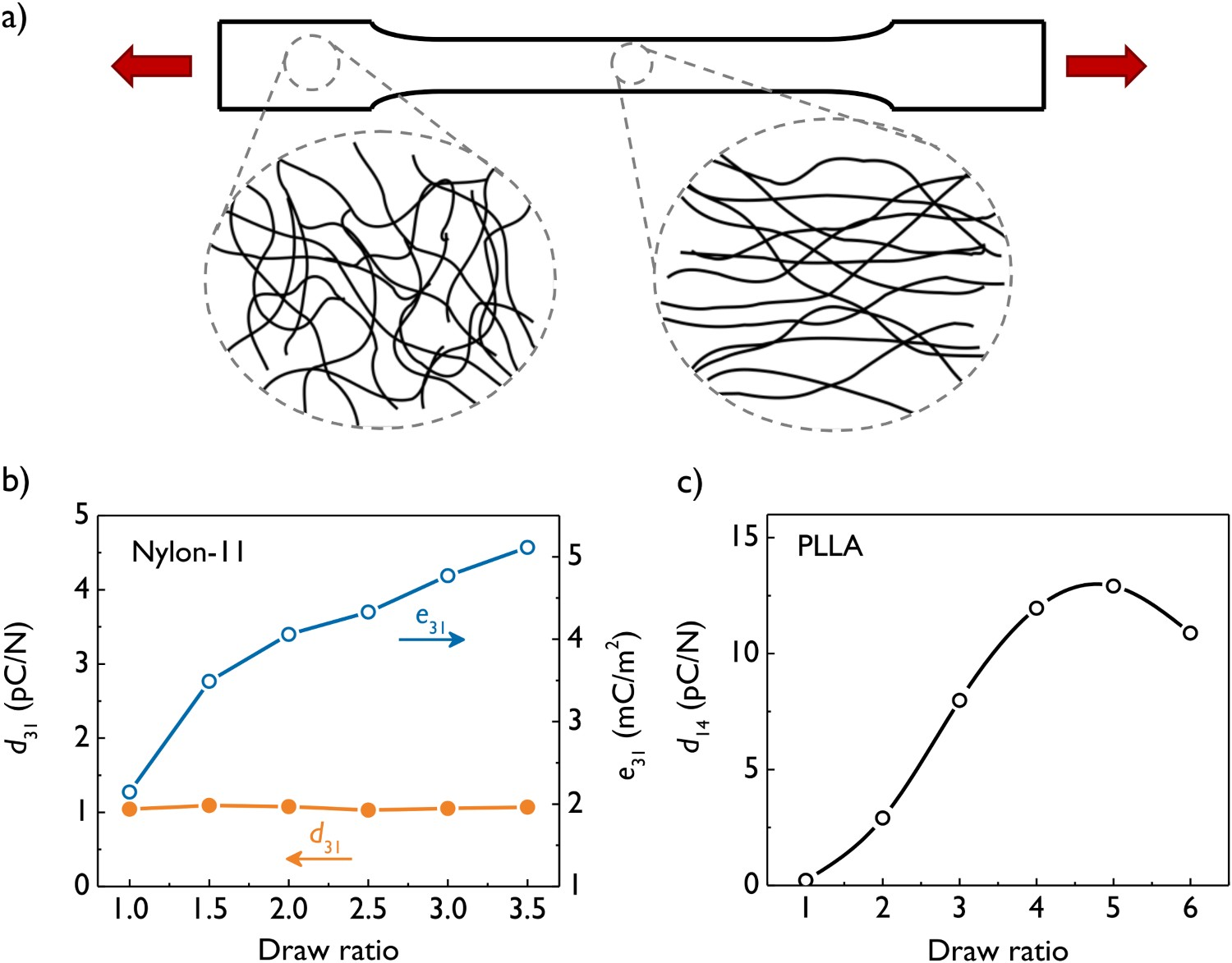
For the reasons outlined in the earlier discussion regarding symmetry, parallel alignment of polymer chains is a sufficient condition for the expression of piezoelectricity in several polymers, including PLLA, PHV, PHB, cellulose and collagen. In PLLA, d 14 generally increases with draw ratio until a maximum value, typically D R ≈ 5–6, as shown in Figure 4(c) [58].
In addition to creating alignment, drawing is also used to induce changes in the crystalline phase of a polymer. The α-phase of PVDF is easily obtained from melt and solution processing, yet does not possess the symmetry required for piezoelectricity. Drawing the polymer results in a strain-induced phase transition to the β crystal phase. This is an all-trans confirmation of the polymer chain, resulting in a polar non-centrosymmetric structure that permits piezoelectricity. It should also be noted that there are other crystalline phases of PVDF, some of which are also polar, albeit with a lower intrinsic dipole moment that the β-phase [76]. The co-polymer P(VDF-TrFE) spontaneously crystallises the polar β-phase, at least in part, and therefore does not necessarily require drawing in order for piezo-/ferroelectric properties to be observed. In many cases, however, drawing is still performed to further enhance the β-phase content.
PLLA is also polymorphic, with its corresponding α and α′ phases being the most common. The β-phase is found in drawn samples of PLLA, the same type of samples which are frequently used for piezoelectric analysis. This has led some researchers to believe that the β-phase is necessary for piezoelectric behaviour [77]. This is incorrect, the β-phase and piezoelectricity are both a consequence of drawing, but the presence of the β-phase is not a requirement for piezoelectricity. Piezoelectricity is observed in samples drawn to a ratio of 2 [58], whereas significant proportions of the β-phase are not formed until draw ratios of at least 4 are achieved [78,79].
The case for drawing is not as obvious when dealing with Nylons. Early work was performed on both drawn [5,46,80] and undrawn [81,82] samples, both of which demonstrated piezoelectric behaviour. Further work demonstrated that the piezoelectric d 31 coefficient is unchanged with respect to the draw ratio in Nylon-11, as shown in Figure 4(b) [69]. The piezoelectric e 31 coefficient was shown to increase with draw ratio, also shown in Figure 4(b), and this was attributed to the increase in elastic modulus that occurs as a consequence of drawing [9]. Even in recent work, studies are still performed either on drawn [71] or undrawn [70,83] samples.
While there is evidence to suggest that cold drawing can induce the disordered δ′ phase [84] in Nylon-11, this phase is also readily achieved by quenching. Drawing of Nylon is therefore not required to achieve the desired phase. Drawing may help to introduce some degree of molecular alignment, but since Nylon samples must be poled before piezoelectric properties can be observed, the anisotropy from drawing is of little consequence. It therefore remains an open question as to the purpose of drawing in preparing piezoelectric Nylon samples.
Poling
Poling describes the process of aligning the dipoles within a material by applying an electric field. This is only possible in ferroelectric materials, since only in these materials is there a spontaneous, remnant polarisation which can be switched by a suitably large electric field. In a (pristine) polycrystalline ferroelectric material, it is likely that the polarisations of the individual grains will be randomly oriented. Even within a single crystal of ferroelectric material, multiple domains of different polarisation orientations can also form. This isotropy introduces a centre of symmetry and therefore eliminates the possibility of piezoelectricity. Aligning the dipole moments throughout the material is required to remove the centre of symmetry and permit piezoelectric behaviour.
In terms of the polymers covered in this review, only PVDF (and co-polymers) as well as odd-numbered Nylons exhibit ferroelectricity. There is some evidence to suggest that even-numbered Nylons can also display ferroelectricity [71]. Therefore, only these materials will benefit from an electrical poling procedure. Noteworthy exceptions to this are polymer piezo-electrets and voided charged polymers. These materials are also poled to induce surface charges which subsequently become trapped, creating dipole moments and therefore instilling piezoelectric behaviour. This class of materials will not be discussed in this review, but more information can be found in references [11,14,16]
Poling can be carried out by attaching electrodes directly to the surface of the material or through a process known as corona poling, whereby the sample is placed beneath a sharply pointed electrode and subjected to a corona discharge, as shown in Figure 5(aiii). The process is often applied as the material is cooled through its Curie point, ensuring that as the spontaneous polarisation arises, it is aligned to a single direction. Figure 5 shows the influence of poling field strength and poling duration on the piezoelectric properties of P(VDF-TrFE) and Nylon-11. (a) (i) A schematic of an un-poled ferroelectric material. The arrows represent dipole moments. (ii) Poling of a ferroelectric material through the use of attached surface electrodes. (iii) Corona poling of a ferroelectric material. This method does not require electrodes to be attached to the material. (b) The influence of (i) poling time and (ii) poling field on the piezoelectric response of P(VDF-TrFE). Data reproduced from reference [62] under the Creative Commons CC BY license. (c) The influence of (i) poling time and (ii) poling field in the d
31 piezoelectric coefficient of Nylon-11. Dielectric breakdown was observed for fields larger than 350 kV/cm. Data reproduced with permission from reference [85] .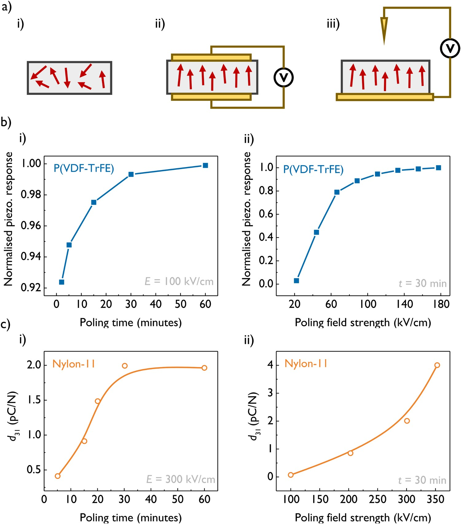
Methods to improve piezoelectric response in polymers
One significant challenge which limits widespread application of piezoelectric polymers is their reduced piezoelectric coefficients when compared with ceramic materials. Several methods have been reported to enhance the piezoelectric response of polymers and this remains an active area of research. Below are some of the techniques that have been used to increase the piezoelectric performance of some selected polymers. As before, however, many of these methods are specific to a particular polymer and may not be transferrable to another.
Co-polymerisation
Co-polymerisation of piezoelectric polymers can be used to modify and improve their electromechanical properties. The common piezoelectric polymer P(VDF-TrFE) is itself a co-polymer and indeed further co-polymerisation is also possible. Additional halogenated molecules such as chlorotrifluoroethylene (CTFE) [86] and chlorofluoroethylene (CFE) [87] are sometimes added to form P(VDF-TrFE-CTFE) and P(VDF-TrFE-CFE), respectively. The influence of the monomer chemistry on the electromechanical properties of these halogenated polymers has been thoroughly reviewed by Soulestin et al. [88].
In addition, block co-polymers of P(VDF-TrFE) with non-halogenated molecules have also been studied. Recent work has demonstrated that ferroelectric properties such as the coercive field and remnant polarisation can be tuned by forming block co-polymers of P(VDF-TrFE) with varying amounts of either poly(2-vinylpiridene) (P2VP) or polystyrene (PS) [89]. The piezoelectric properties of the block co-polymers were not investigated in this study, but it is likely that they too would be influenced by the co-polymer composition.
Additives
The use of additives or ‘fillers’ is a common method to enhance the piezoelectric properties of polymers. Through this method, the piezoelectric response is increased either by including additional piezoelectric materials with larger piezoelectric coefficients than the original polymer or by using an additive that modifies the structure and/or properties of the polymer itself in such a way as to augment its piezoelectric response. The use of additives in piezoelectric polymers is well reviewed by Mishra et al. [8]. A short discussion of the method is presented here, but the interested reader is directed to the aforementioned review.
With regard to additives which are themselves piezoelectric, particles of PZT, BaTiO3 and ZnO are frequently used [8]. These are well-established piezoelectric materials which can have piezoelectric coefficients hundreds to thousands of times larger than that of polymers [18]. Typically, the piezoelectric fillers are added as nano- or micro-particles to form 0–3 composites with the piezoelectric polymer. Generally, the piezoelectric coefficient of the composite increases with the relative fraction of piezoelectric additive, as shown in Figure 6(a). PVDF and its co-polymers are frequently used as the piezoelectric polymer matrix [90], but examples using polyamides [91,92], cellulose [93] and other polymers can also be found [8]. (a) The piezoelectric coefficient d
33 of a PZT/PVDF 0–3 composite as a function of PZT content. All samples were electrically poled for 30 min at 110°C using a field of 10 kV mm−1. Data reproduced with permission from reference [94] . (b) The influence of multi-wall carbon nanotube (MWCNT) content on the β-phase content of PVDF, as measured by wide-angle X-ray diffraction. Data reproduced with permission from reference [95] . (c) A schematic representation of how layered silicate nanoclays, in this instance Lucentite, can nucleate the β-phase in PVDF. Figure adapted with permission from reference [96] .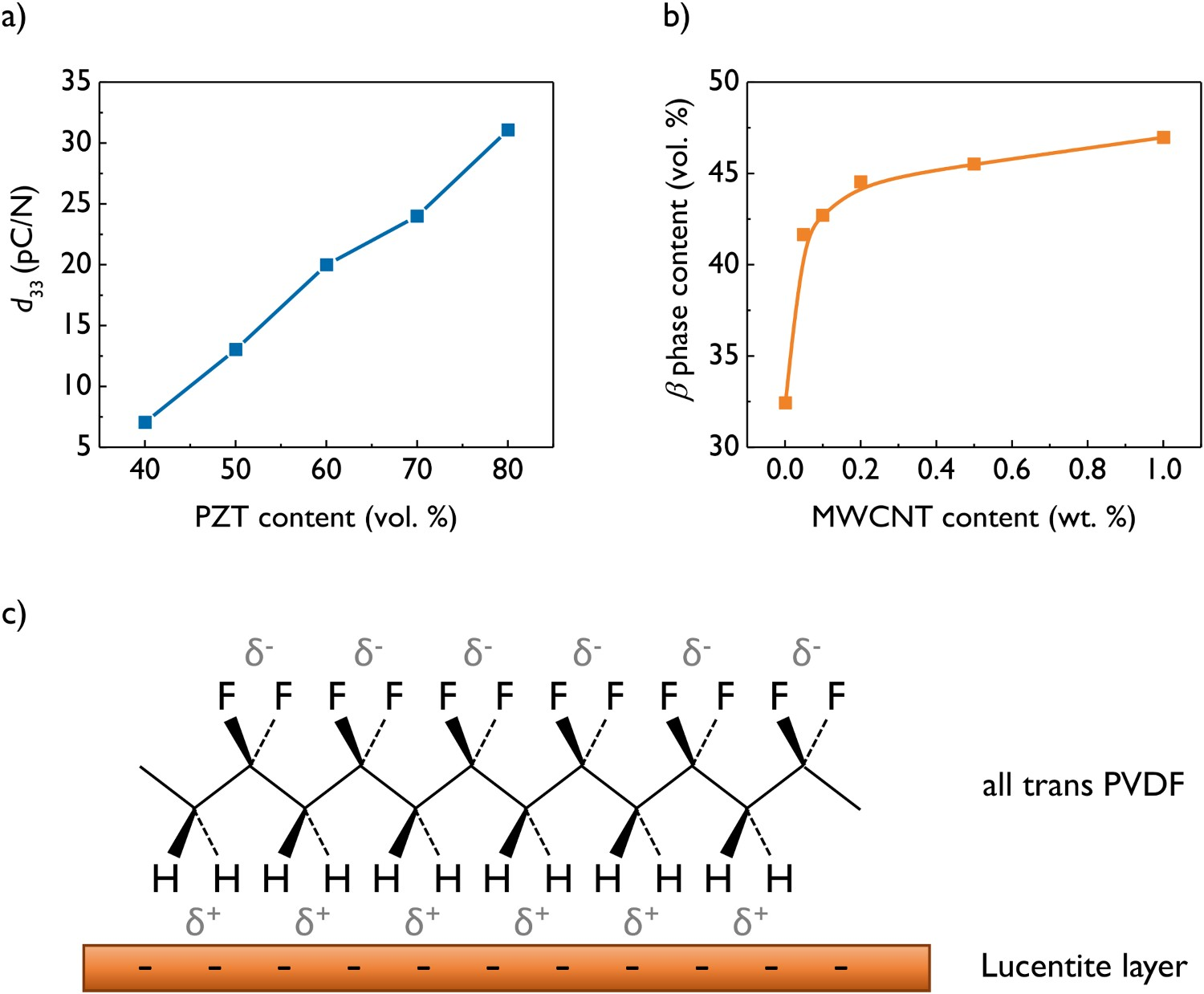
When creating a piezoelectric composite, some consideration must be given regarding how the anisotropy of each component will be preserved during fabrication or induced once the sample is formed. Furthermore, some thought must be given to how the two components will interact with each other. For example, d 33 of PZT is positive while that of PVDF is negative, which can lead to a nullification of the overall piezoelectric response if both domains are polarised in the same direction [97].
The use of non-piezoelectric additives relies on the ability of the filler material to modify the properties of the piezoelectric polymer. Often, the action of a filler is to induce or promote a phase change, as shown schematically in Figure 6(c). Almost exclusively this method is performed on PVDF and its co-polymers, where fillers such as carbon nanotubes [95], graphene oxide [98,99] layered silicate nanoclays [100–103], metallic salts [104], ionic liquids [105] and metallic nanoparticles [106] can be used to promote the formation of the electroactive β and γ phases. This is shown for the case of multi-wall carbon nanotubes (MWCNT) in Figure 6(b). Higher contents of these phases can in turn lead to increases in the piezoelectric coefficients.
Aside from PVDF, acrylic polymer additives have been shown to increase the piezoelectric response of PLLA [107]. Symmetric co-polymers of poly(methyl methacrylate) and poly(butyl acrylate) added to PLLA were found to bind selectively to the crystalline regions and increase the degree of chain alignment for a given draw ratio. Under optimised conditions, the piezoelectric coefficient was doubled with respect to the untreated material. The use of additives has since been used to create piezoelectric structures from 3D printed PLLA [108].
Morphotropic phase boundaries
In some ferroelectric ceramics, piezoelectric properties are maximised in the vicinity of a morphotropic phase boundary (MPB). These are regions in the phase space of a material where a change in phase occurs as a result of a change in composition (or occasionally, a change in pressure). It is well documented that lead zirconium titanate (PZT) possess an MPB between tetragonal and rhombohedral phases, and that the intermediate monoclinic phase in the vicinity of this boundary permits facile dipole rotation, resulting in significantly increased piezoelectric properties [109].
Recently, it has been reported that P(VDF-TrFE) displays characteristics which imply it too possess a MPB [110]. The MPB is apparent by observing the crystal structure, polymer chain conformation and ferroelectric properties as a function of the relative fractions of VDF and TrFE in the co-polymer, as shown in Figure 7(a(i)). As can be seen in Figure 7(a(ii)), a clear maximum in piezoelectric properties can be observed at around 50 mol % VDF. The mechanism of this behaviour is currently being studied [111], although it is possible that a similar dipole-rotation mechanism can explain the observations. (a) (i) The MPB in P(VDF-TrFE), shaded green. The data points represent the transition to the paraelectric phase within the crystalline regions of the polymer. Data were collected by two different material characterisation methods, DMA and DSC. The labels [O, D, P] refer to the state of the crystalline structure: O, ordered; D, disordered; P, pseudo-ordered. (ii) A large increase in d
33 is observed around the MPB. Figures reproduced with permission from [110] . (b) A schematic representation of the SSE method used to produce crystalline and aligned films of piezoelectric polymers. Figures adapted with permission from [112] .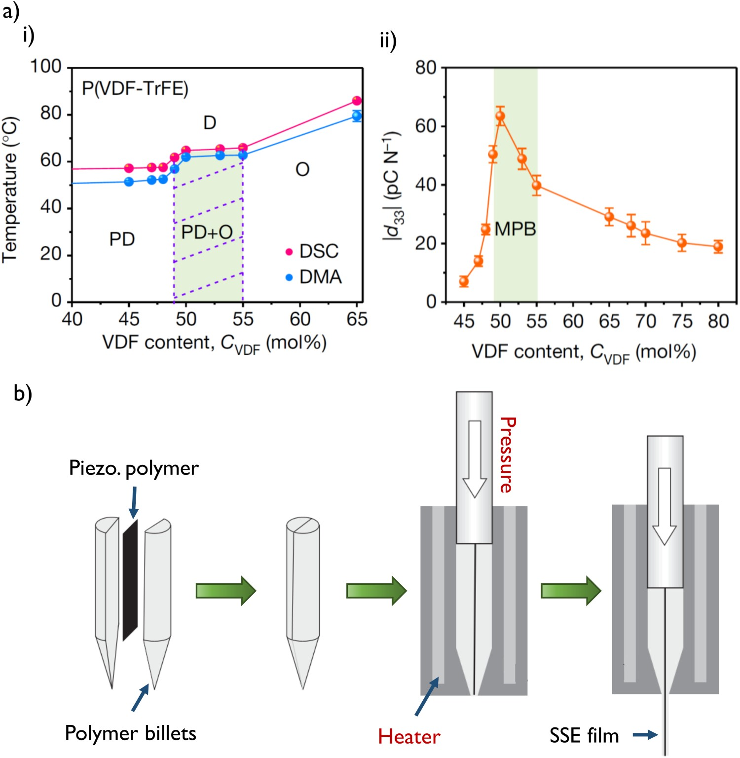
Modifications to processing methods
As outlined in the earlier section discussing processing of piezoelectric polymers, drawing is a common method to produce aligned samples. Drawing can only be carried out on amorphous or slightly crystalline samples since the stress concentrations around large crystallites cause the material to crack when under tension. It is often necessary to use additional annealing steps after drawing to increase the crystallinity of the sample. However, during crystallisation, much of the initial chain alignment can be lost as isotropic crystalline structures form in the material.
To overcome this, solid-state extrusion (SSE) has been used to produce highly aligned and highly crystalline samples. In SSE, the polymer of interest is sandwiched between two sacrificial polymer billets and the entire assembly is forced through a metal die at high pressure (>200 MPa) at an intermediate temperature between T g and T m, as shown in Figure 7(c). The compressive stresses from the walls of the extrusion die and the support of the sacrificial billet allow for the procedure to be carried out on an already crystalline starting material. Extrusion through the die breaks up the higher order structure of these crystalline regions and forces them into alignment, creating a film that is both crystalline and aligned. In some cases, the applied stress can cause a transformation between crystal phases [113].
Yoshida et al. [112] used SSE to create piezoelectric PDLA samples with d 14 values ∼1.5 larger than films uniaxially drawn to the same draw ratio. SSE has also been used to create piezoelectric samples of PVDF, once again displaying improved piezoelectric properties compared to drawn samples [114,115].
The idea of disrupting the higher order crystalline structure to improve piezoelectric properties has also led to the use of supercritical CO2 treatment on PLLA. This procedure leads to changes in the higher order structure [116], resulting in nano-rod type crystals rather than conventional spherulite structures. Imoto et al. demonstrated that performing this treatment on drawn PLLA samples resulted in a two-fold increase in the value of d 14 [117].
It was mentioned previously that PLLA is one of two stereoisomers, and that the other isomer – poly-
Nanostructuring
It is often found that the properties of a material are improved as its physical dimensions are reduced. Many researchers use this approach in an effort to increase the piezoelectric performance of polymers by creating nanostructures [119,120]. The definition of ‘nanostructure’ is somewhat ambiguous and will vary between disciplines. Here, we will take nanostructure to mean any feature with one or more dimensions that measure <500 nm. Typically, these structures take the form of nanowires or nanotubes, although more complex geometries are also possible.
Two of the most common nanostructuring techniques for polymers – electrospinning and template wetting – are depicted in Figure 8. An important point to consider when dealing with nanostructured piezoelectric polymers is the need to create some anisotropy in the molecular structure since drawing the material is no longer an option at these length scales. In many cases, however, the growth method itself leads to some inherent molecular orientation. This is discussed in more detail with respect to each method below. (a) (i) A schematic of the electrospinning process. Figure reproduced with permission from reference [121] . (ii) Typical polymer nanofibres produced via electrospinning. Image reproduced from reference [122] under the Creative Commons CC BY license. (b) (i) A solution template wetting process to produce PLLA nanowires, shown in part (ii). Figures reproduced from reference [123] under the Creative Commons CC BY license.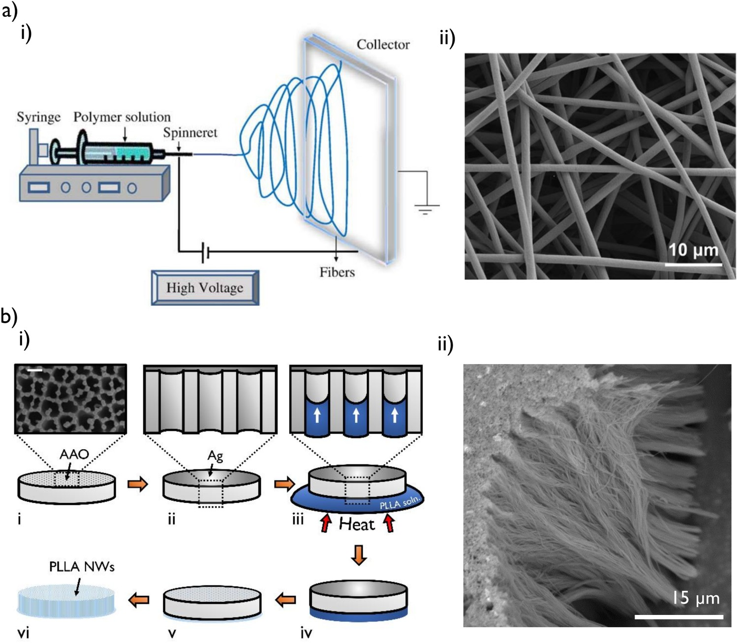
In electrospinning, a polymer solution is ejected through a fine nozzle towards a substrate, often called a collector, as shown in Figure 8(a). A large electric field (of the order of kV cm−1) is applied between the nozzle and the collector which acts to overcome the surface tension of the polymer solution, creating a very fine jet of liquid. These jets solidify as the solvent evaporates to create fibres of the polymer. These fibres can have diameters of tens to hundreds of nanometres and under appropriate conditions can be highly crystalline.
The high shear forces associated with the flow of solution through the nozzle can lead to significant molecular alignment in the nanofibres [124,125], effectively ‘drawing’ the polymers without the need to mechanically apply a force. As a result, electrospinning is frequently used to create piezoelectric polymer nanostructures [126–128]. The large electric field applied during the process can also influence the materials’ structure. The polarity of the field, for example, can influence the surface chemistry of PVDF [129] and consequently its piezoelectric properties.
Consideration must be given to how electrospun fibres are collected. Electrospinning typically results in a random mat of nanofibres. The random orientation distribution means that the mat will be centrosymmetric, even if each nanofibre has a large degree of molecular alignment. Rotating collectors can produce uniaxially aligned nanofibres, which depending on the polymer symmetry may or may not be sufficient to permit piezoelectric behaviour.
Template wetting is another versatile and facile technique that has been widely used in many separate fields to create nanostructures of different types of materials, including polymers [130–135]. The process involves infiltrating a nano-porous template with the desired material and subsequently removing the template to reveal the nanostructures that have formed within the pores, as shown in Figure 8(b(i)).
Template materials include porous silicon [136], track-etched polymer membranes [137] and anodised aluminium oxide (AAO) [138]. The latter is the most common due to its temperature and chemical stability, the ability to control its pore geometry as well as its wide availability as particulate filter membranes [131]. Porous AAO membranes are typically 1–100 μm thick, with cylindrical through-thickness pores ranging in diameter from 10 nm to several micrometres. Depending on the growth conditions and number of anodisation cycles, these pores can be arranged in a regular lattice or randomly spaced. Once infiltrated, AAO templates can be removed by etching with acid or base, typically phosphoric acid or sodium hydroxide.
For polymers, infiltration occurs from either a solution or from the polymer melt. As a very general rule, infiltration with solutions gives solid nanowire structures, while infiltration with the polymer melt gives hollow nanotubes structures [139,140]. The confined environment of the nanopore often leads to preferential alignment of the polymer chains [141–144]. This can be parallel or perpendicular to the pore axis, depending on the polymer system and the template material used. This confinement-induced alignment makes template wetting a viable nanostructuring method for piezoelectric polymers. There are several reports of nanostructured PVDF (and co-polymers) [137,145–147], Nylon-11 [148,149], PLLA [31,68,123] and even cellulose nanostructures [150] produced in this manner.
Characterisation of piezoelectric polymers
To fully characterise the piezoelectric effect in polymers, it is necessary to characterise both the electromechanical response and the polymer structure. The orientation and crystal phases present in the polymer structure will determine the setting of the axes used to describe the piezoelectric matrix. Knowing how these axes are orientated will give context to the electromechanical measurements from the sample.
Typical electromechanical characterisation methods for piezoelectric materials, such as laser interferometry, piezoresponse force microscopy (PFM) and standard piezometers are also broadly applicable to piezoelectric polymers. However, it is worth noting that when taking electrical measurements, such as open-circuit voltage, it is important to consider the output impedance of the piezoelectric polymer device. This can be very large, typically several megaohms or more, because polymers are highly insulating. The input impedance of the measurement equipment must be significantly greater than the output impedance of the device in order to obtain accurate readings. Peripheral circuity such as unity gain buffers (also known as voltage followers) and charge amplifiers can be useful in this regard.
There are numerous techniques for performing material characterisation of polymers, several of which are very useful for piezoelectric polymers. It is important to determine if any orientation exists in the material, and if so in which direction(s) this occurs. For some polymer systems, it is also useful to identify which crystal phases are present [151]. Differential scanning calorimetry (DSC) can be used to estimate the crystalline fraction of the polymer and give hints towards identifying the crystal phases present. X-ray diffraction (XRD) can also provide crystallinity data as well as more rigorous phase identification. XRD data can also be used to infer if any preferential alignment exists in the material. Fourier transform infrared (FTIR) spectroscopy is another useful tool to identify the presence of certain crystal phases. By using a polariser with this technique, it is also possible to check for alignment of polymer chains within the sample. Furthermore, polarised light optical microscopy (POM) is a simple but powerful technique which can be used to directly visualise the orientation of polymer chains. When combined with a wave plate and a reference sample, this can give unambiguous information about the polymer chain alignment [68].
A brief review of applications of piezoelectric polymers, including current and future applications in cell biology
There are numerous applications of piezoelectric materials. Several household items are dependent on the piezoelectric effect – piezoelectric materials generate sparks in gas lighters and help to keep time in digital watches through carefully tuned mechanical oscillations. Piezoelectric materials are also used throughout academia and industry. The linear and reversible coupling between stress and polarisation exhibited by piezoelectric materials enables highly precise actuators and sensors.
The vast majority of these devices are fabricated from piezoelectric ceramics. Often, the reduced piezoelectric coefficients and low elastic moduli of polymers preclude piezoelectric polymers from many applications. For example, while a piezoelectric polymer actuator may produce a greater amount of strain compared to its ceramic counterpart, the polymer will not be able to exert the same level of force. Furthermore, sensors which depend on the propagation of mechanical oscillations, such as surface acoustic wave (SAW) and film bulk acoustic resonator (FBAR) biosensors [152] typically demonstrate greater sensitivity when fabricated from rigid ceramic materials, which generally show less attenuation than polymeric materials [153].
Nonetheless, in some instances, the mechanical properties of piezoelectric polymers may be beneficial. The acoustic impedance of PVDF matches well with that of water, meaning that hydrophones and ultrasonic transducers made from PVDF can be used without quarter-wave matching [154]. The compliance of PVDF also means that highly flexible strain sensors can be fabricated, and indeed, these are commercially available as films and cables [155].
Academic and industrial research into piezoelectric polymers is broadly focused around three main areas: tactile sensors for flexible and wearable electronic devices, mechanical EH devices and electroactive substrates for cell biology.
Tactile sensors
There are several examples demonstrating the use of PVDF as the active material in tactile sensors. These devices are intended to function as pressure-sensitive touch panels for flexible electronic devices [156,157]. Single or mutli-electrode arrays are deposited onto films of poled PVDF to create a parallel-plate capacitor type structure, as shown in Figure 9(b). Force applied to the sensor can then be monitored as charge (or voltage) on these electrodes. (a) A commercially available piezoelectric PVDF sensor. Image credit [155]. (b) A section of a P(VDF-TrFE)-based tactile sensor array. Figure reproduced with permission from reference [157] . (c) (i) An EH device comprised P(VDF-TrFE) nanowires grown by template wetting. (ii) The open-circuit voltage and short-circuit current of this device when subjected to cyclic loading. Figures adapted from reference [145] under the Creative Commons CC BY license. (d) (i) A schematic operating principle of a nanostructured piezoelectric cell culture surface. Compliant piezoelectric nanostructures are deformed by an adherent cell, generating surface charge. (ii) A human dermal fibroblast growing among an array of piezoelectric PLLA nanotubes. Figures reproduced from reference [31] under the Creative Commons CC BY license.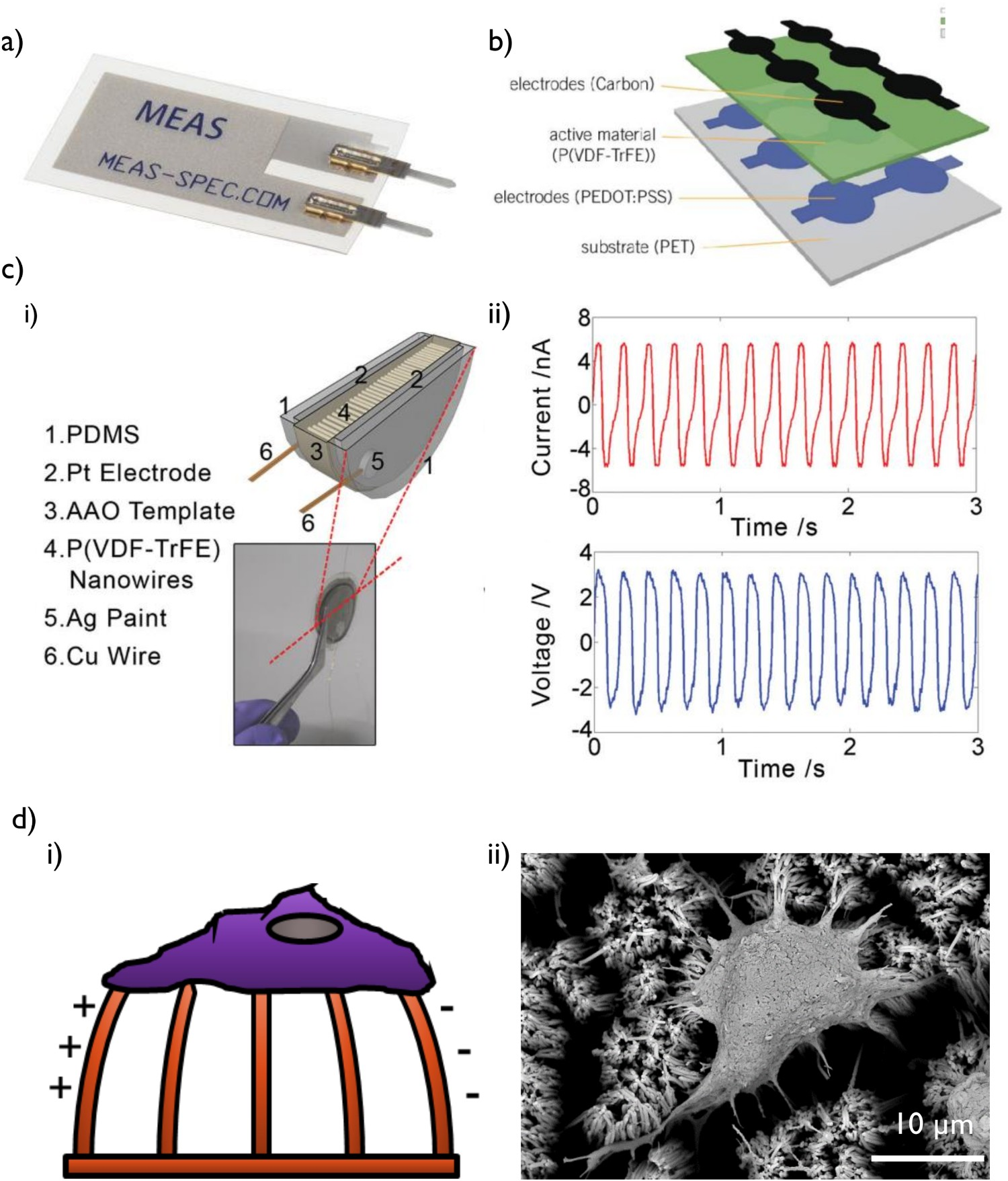
As well as piezoelectricity, PVDF is also known to exhibit pyroelectricity – a change in polarisation as a result of a change in temperature. If this behaviour is not accounted for, then the signal from a PVDF touch sensor is ambiguous – is a change in the amount of charge detected the result of a greater force, or a change in temperature? The pyroelectric coefficient of PVDF is approximately −300 × μC m−2 K−1 [158]. Compared with the piezoelectric coefficient d 33 ≈ −30 pC N−1, it can be seen that a 1 K change in temperature results in a change in surface charge equivalent to varying the pressure on the material by 1 kPa.
It is possible to eliminate the pyroelectric response of the material either using filtering of the electrical signal [159] or by using an appropriate device design [160]. Consider two oppositely poled sensors placed in the same location, but with differing physical orientations. An increase in temperature will develop an equal but opposite voltage across each sensor. An applied stress, however, will generate different voltages across each device, since the stress will couple differently to each sensor due to their dissimilar orientations. Electrically connecting these sensors together results in a cancellation of the pyroelectric response without nullifying the piezoelectric response.
Schemes such as this have yet to be applied to PVDF tactile sensors. Doing so would require multiple poling directions within the same film, or multiple discrete transducers connected together to form a single device. PLLA does not possess pyroelectric properties and hence does not encounter this problem. However, its shear piezoelectricity means the device must be carefully designed to ensure that an applied force will couple to the non-zero piezoelectric coefficients. Draw films of PLLA have been used to create pressure-sensitive touch panels [161,162].
Energy harvesting devices
EH describes the idea of converting waste sources of energy, perhaps structural vibrations or body motion, into electrical energy. This energy can then be used to do some useful work such as power a wireless sensor node or charge the battery of a wearable device. One method of transducing mechanical and electrical energy is through the use of piezoelectric materials: the mechanical stimulus is used to deform a piezoelectric material, which subsequently becomes polarised and the resulting electric field can be used to move charge through an external circuit [163]. An example piezoelectric energy harvester is shown in Figure 9(c). The field of piezoelectric energy harvesting (PEH) is well established and the topic has been thoroughly viewed by several authors [164–166].
There is significant interest in using piezoelectric polymers as the basis for mechanical energy harvesters [167–169]. At first, this may seem surprising, given that the electromechanical coupling coefficient (kij 2) – an important figure of merit for piezoelectric materials [170] – of piezoelectric polymers is significantly smaller than that of ceramic materials (PVDF: k 31 2 ≈ 0.01, PZT: k 33 2 ≈ 0.45) [167].
However, k ij 2 refers only to the efficiency of the conversion between stored mechanical and stored electrical energy. In stress-driven scenarios (deformation under a fixed stress, rather than to a fixed strain), the amount of stored mechanical energy is inversely proportional to the elastic modulus of the material. Under these conditions, compliant piezoelectric polymers can therefore store significantly more mechanical energy than rigid ceramic materials. Despite the low internal conversion efficiency of piezoelectric polymers, the large amount of mechanical energy stored initially means that the amount of electrical energy available for transmission can still be substantial [171,172]. The mechanical properties of polymers may also be beneficial when matching the mechanical impedance of the EH device to the source of mechanical energy to ensure maximum power transmission.
The term ‘nanogenerator’ is frequently used to describe EH devices, including those designed around piezoelectric materials. The name is a legacy from the first demonstration of the technology, which reported the piezoelectric voltage induced across zinc oxide nanowires when deformed by an AFM tip [173]. Subsequent devices were also called nanogenerators, despite many not actually containing any nanomaterials. Nonetheless, many researchers continue to fabricate EH devices from nanomaterials.
The reasons for this are two-fold. First, nanostructuring can reduce the effective stiffness of a material. The arguments above about more compliant piezoelectric materials being a more suitable choice for stress-driven nanogenerators therefore apply. Second, the piezoelectric properties of materials are often observed to improve as material dimensions are reduced – as discussed in the Characterisation of piezoelectric polymers section.
Biological applications
A surprising number of biological materials are themselves piezoelectric. Piezoelectric behaviour is observed in wood, bone, tendon, skin, DNA and countless other natural materials [7,21,24]. As a result, there is much interest in studying how artificial piezoelectric materials influence and stimulate cellular function. Understanding and developing piezoelectric materials is therefore also relevant for high level, fundamental research in the physical and life sciences.
Over the last decade, there has been a huge increase in the use of piezoelectric materials in cell culture applications. The topic is discussed well in a number of recent reviews [37–44]. Briefly, cells are cultured onto piezoelectric materials and aspects of their behaviour are monitored. These observations are then compared with those from non-piezoelectric surfaces to deduce the influence of the piezoelectric effect.
Typically, cells are cultured directly onto scaffolds made from piezoelectric ceramics [43,174,175] piezoelectric polymers [176–178] or polymer/ceramic composites where one or both components may be piezoelectric [179,180].
Piezoelectric polymers have some distinct advantages in these cell culture applications. First, piezoelectric polymers are generally considered to be more biocompatible than piezoelectric ceramics [41]. Fewer coatings and adhesive factors are required, if at all, and therefore the biological material can be in direct contact with the piezoelectric material, increasing the influence of the piezoelectric charge. Many piezoelectric polymers are also biodegradable, creating the possibility of transient piezoelectric devices.
Second, polymers are typically softer, more flexible and tougher than ceramic materials. This is a major advantage in cell culture applications. Biology is exceptionally sensitive to mechanical stimuli [181]. Changing the Young’s modulus of a cell culture substrate, for example, can have a significant influence on the cellular behaviour [182]. When developing a piezoelectric device for cell culture applications, it is therefore important to match the mechanical environment in vitro to that in vivo. Polymers come closer to matching the mechanical properties of most biological materials than ceramics.
Furthermore, the ability to easily nanostructure piezoelectric polymers means that the effective stiffness of the polymer surface can be significantly reduced. Vertically aligned nanostructures have sufficiently low bending stiffness to be bent by the traction forces of an adhered cell. For appropriate piezoelectric polymers, the strain from bending will couple to one of the non-zero dij coefficients and generate a piezoelectric charge. The attached cell can therefore stimulate itself simply by interacting with its environment, as illustrated in Figure 9(d), without the need for an external transducer. Devices using this principle have been fabricated from PLLA [31].
Conclusions
In this review, we have discussed both theoretical and practical aspects of piezoelectricity in polymers. The effect in polymers was rationalised by considering the symmetry of polymer molecules and the restrictions this places on the observed response. Three polymers, namely PVDF, odd-numbered Nylons and PLLA, were used as examples to discuss the phenomenon. The theory of exactly how piezoelectricity arises was briefly discussed, highlighting that this is an important open question in the field, and one that probably does not have a unique answer: the mechanism in each polymer is most likely different. This is a topic that certainly deserves future work.
The processing of piezoelectric polymers was also reviewed where it was stressed that the processing required for each polymer can differ significantly. Some methods used to enhance the piezoelectric effect in polymers were also discussed. Finally, some applications of piezoelectric polymers were presented. It is hoped that this discussion will be useful in developing the understanding of piezoelectric materials and to focus research efforts into the areas of the field that are not well understood. A deeper understanding of piezoelectricity in polymers will not only satisfy academic curiosity, but also lead to technological advances in industrial, medical and engineering applications.