
Abstract
This review examines the development and current state of Cu-rich Cu–Cr–Nb alloys commonly referred to as GRCop or Glenn Research copper alloys with emphasis on Cu–8Cr–4Nb (at%), or GRCop-84, and Cu–4Cr–2Nb, or GRCop-42. Recent additive manufacturing efforts have increased interest in GRCop alloys, and full-scale hardware has been fabricated using AM techniques and practical hot-fire tests have been conducted, but structure–property relationships are still under development. The development, processing, and current microstructure-property relationships of GRCop alloys are reviewed along with comparisons to similar high-heat-flux Cu alloys including NARloy-Z, GlidCop Al-15, AMZIRC, Cu–1Cr–0.1Zr, and Cu–0.9Cr. The review concludes with an assessment of future prospects for GRCop alloys and overview of advantages provided by additive manufacturing.
Introduction
Excessive heat flux from or onto surfaces has been a major limiting factor in the development of various technologies such as turbines, rockets, or electronics [1]. The term ‘high-heat-flux applications’ is used to describe these and similar uses where the heat flux is subjectively high and difficult to manage and has been ascribed to a multitude of applications from welding equipment to fusion reactor components [1–4]. Defining a range for high-heat-flux is difficult since its perception has evolved with time and differs between different fields and industries. Most engineering disciplines consider >1 MW m−2 as high-heat-flux [5]. In the realm of microprocessor cooling for example, Ebadian et al. classify 1–10 MW m−2 as high-heat-flux and denote 10–100 MW m−2 as ‘ultra-high-heat-flux’ and >100 MW m−2 as ‘extreme-heat-flux’ [5]. However, these terms are rarely used outside of the microprocessor field, so the term high-heat-flux will primarily be used broadly here to encompass everything above 1 MW m−2. For reference, a typical burning room during a house fire releases heat flux on the range of 0.001–0.01 MW m−2, while the maximum allowed heat flux in a fission reactor is roughly 1 MW m−2 in the fuel cladding which is 1% of the heat flux at the surface of the sun [6,7]. One method of mitigating excessive heat flux is to use a high thermal conductivity material to rapidly transfer heat by active or passive cooling. Copper is a standard for heat transfer media due to its relative cost, formability, and conductivity, and numerous alloys with a variety of elements have been used to fulfil various roles in industry. One of these alloys is Cu–8Cr–4Nb (at%) or GRCop-84 (Glenn Research Copper alloy 84) which was formulated for NASA’s Space Shuttle Main Engine (SSME) for a component with heat flux on the order of 100 MW m−2 but was not put into service due to large time and monetary investments in its predecessor, NARloy-Z. The term ‘GRCop-84’ will be used to specifically denote Cu–8Cr–4Nb and GRCop will classify similarly Cu-rich Cu–Cr–Nb alloys like GRCop-42, although the focus will be on GRCop-84 which has more available literature. GRCop-84’s creep, conductivity, low cycle fatigue, tensile strength, and thermal expansion properties are among the best available at high temperatures up to approximately 973 K [2]. GRCop-84 has shown potential for numerous high-heat-flux applications including resistance welding electrodes and holders, permanent metal casting moulds, vacuum plasma spray nozzles, fusion reactor first walls, or any high temperature heat exchanger in the past, but recent advances in additive manufacturing (also known as 3D printing) and metallurgy have extended its utility [2,8,9]. While this has renewed interest in GRCop-84, the majority of the development of the alloy remains in technical documents and older papers that are overshadowed by more recent publications. GRCop-84 has become an intrinsic component to NASA’s additive manufacturing based Low-Cost Upper Stage Propulsion (LCUSP) project and Rapid Analysis and Manufacturing Propulsion Technology (RAMPT) and full-scale, quality tested hardware has been developed [10–12]. The objective of this review is to provide the context of GRCop-84 from the perspective of the Space Shuttle development and relevant properties and scientific theory to help facilitate its continued development and application.
Background
Following the historic moon landing in 1969 during the Apollo project, the largest arguable obstacle to further human operated space exploration and development was its high cost. Concepts from as early as the 1950s advocated the use of reusable launch vehicles for reducing cost but were not technologically viable [13]. The majority of the necessary developments in technology were made during the Apollo project and led to the eventual approval of the Space Shuttle program in 1972 [13]. The primary goal of the Space Shuttle was to provide a consistent and reliable mode of transportation for the parts and crew to the International Space Station with high payload and safety requirements. The final design of the Space Shuttle consisted of the Orbiter Vehicle which held the crew and cargo, expendable tanks of liquid hydrogen and oxygen, and a pair of recoverable solid rocket boosters. Entry into orbit could be achieved by combining the thrust from the solid rocket boosters and Orbiter Vehicle’s engines, but NASA engineers found that existing engines would not be sufficient to meet the weight and safety requirements [13]. As a result, a development contract was awarded to Rocketdyne in 1971 to develop a new engine that would eventually become the RS-25 engine or Space Shuttle Main Engine (SSME), which is shown in its relative position to the Space Shuttle in Figure 1 [13,14]. General Space Shuttle outline and inset of diagram of the RS-25 SSME adapted from [1].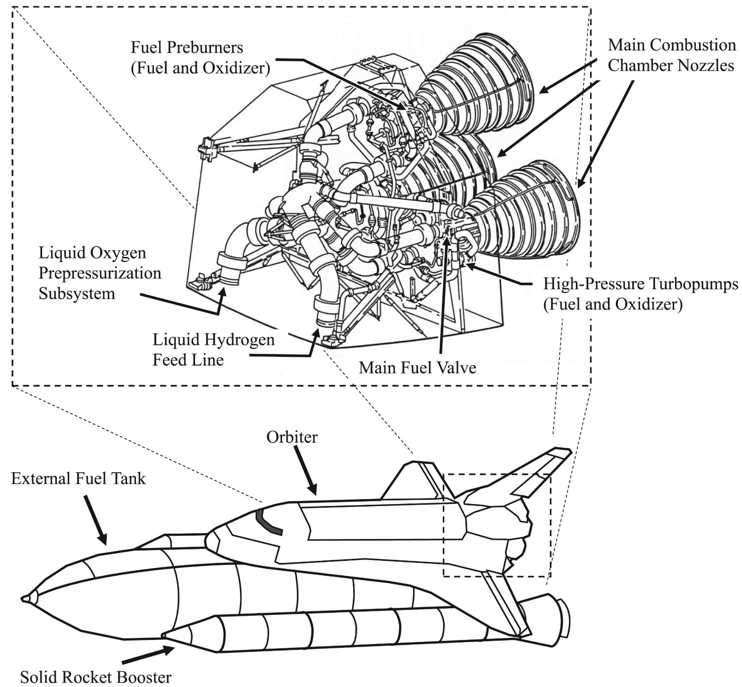
A key component of the SSME was a new high-performance combustion chamber design that raised the throat heat flux of previous designs from 32 MW m−2 (20 Btu in−2 s−1) to 114–164 MW m−2 (100 Btu in−2 s−1), which could accommodate the increased payload requirements [15,16]. The SSME’s combustion chamber contains the combustion reaction of propellants and generates thrust through supersonic expansion in the throat that is passed out the nozzle; these essential components are shown in Figure 2 [17]. The combustion chamber was predicted to have operating conditions of 3600 K and ∼20 MPa, though these predicted values vary between sources, and required regenerative cooling and a high thermal conductivity structural liner to dissipate heat and resist thermal strain [15,17]. The temperature environment of the nozzle is significantly lower, so a lower cost, from a fabrication and raw material perspective, steel alloy or superalloy can be used instead. The pressure generated by the combustion reaction is mostly negated by mechanical support provided by an external jacket of IN718, but the rigid reinforcement does not aid in reducing the high thermal strains [16,17]. Sketch of essential components of SSME combustion chamber and nozzle without injector demonstrating path of cooling chambers built parallel to height of the nozzle; not to scale.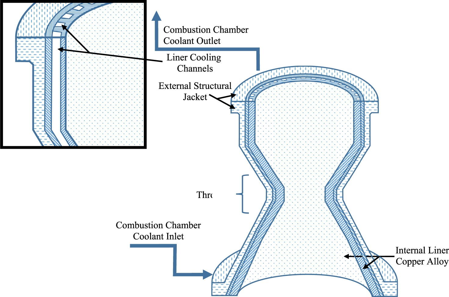
Regenerative cooling was achieved by flowing liquid H2 through rectangular cooling channels machined into the liner that also functioned as the path to the fuel injectors, see Figure 2. These channels were machined by milling into the edges of the liner in a rectangular configuration parallel to the length with a subsequently added shell to enclose the channels with a close-out by electro-forming, or a similar process [18,19]. Due to the complicated geometry of the liner, this was likely the most reliable method to add cooling channels at the time despite high machining costs and limited tolerances. Forming a combustion chamber in a single piece with built-in cooling channels without the need for machining would likely improve cooling rates, overall reliability, and cost efficiency but was effectively impossible at the time. Higher machining tolerances or built-in channels would allow for overall improvements to the design geometry such as the aspect ratio, number, and position of the channels [18]. Future computer analysis and fabrication methods would eventually be found and used to optimise the channels to some extent [18]. Under the high active-cooling gradient between the heat of combustion and liquid hydrogen, respectively, a typical rocket engine liner will have an operating temperature, often referred to as a ‘hot-wall’ temperature, ranging from 673 to 973 K depending on cooling efficiency from thickness and conductivity of the channel walls [2]. This hot-wall temperature range could be endured by a variety of materials, but NASA had another critical requirement that would prove to be the most difficult to meet: the SSME needed to be reusable with limited repair and re-conditioning to reduce cost. Even if a material could initially meet initial property requirements set by NASA, performance considerations of creep, low-cycle fatigue (LCF), and other time dependent mechanisms dramatically increased the design challenge.
A new alloy was needed to fulfil these conditions and Rocketdyne developed a copper alloy based on their previous work with NARloy-A, a cast Cu-3.5Ag (wt-%) alloy, by adding Zr to a ratio of Cu–3Ag–0.5 Zr (wt-%) and vacuum melting and vacuum centrifugally casting [16]. Copper was the base material due to its ability to function as a structural material along with its balance of cost, thermal conductivity, and mechanical strength. Cu–3Ag–0.5 Zr was trademarked NARloy-Z and formed into combustion chamber liners by a combination of hot spun forging and machining by Rocketdyne [16]. After the original production, the equipment was dismantled, and NASA had to reproduce a chemically equivalent version of the alloy with conventional melting, casting, and forging methods, designated as NASA-Z, when new liners were needed [16]. Other groups have had similar success including Krishna et al. who reproduced a similar Cu–Ag–Zr alloy with a combination of vacuum induction melting, hot forging, and rolling [20]. AMZIRC, a Cu–Zr alloy, was the primary competitor at the time for fatigue resistance, but NARloy-Z demonstrated longer and more uniform cycle lifetimes under realistic thrust chamber conditions [16]. Despite being the best available alloy, NARloy-Z was not able to fully meet reusability specifications and reusability life requirements were reduced from 100 missions in 1973 to 55 in 1980 [17,21].
Regardless of its limitations, NARloy-Z was used in each space shuttle engine until the last launch in 2011 with roughly 40 years of development and investment focused on ensuring the reliability of the NARloy-Z engines. Replacing a critical component like the liner requires thorough testing and evaluation over many years, even though relatively small improvements from a new alloy could be economically worthwhile by improving load capacity or safety margins [22]. Although NARloy-Z remained in service, it was limited by its maximum operating temperature and reusability, leaving an opportunity for the development of a more optimised replacement. NASA and independent researchers were investigating new alloys capable of meeting the original standards of the SSME. Their goal was to develop a reusable copper alloy that would be thermally and mechanically stable during operation as a combustion chamber liner with primary criteria of mechanical strengthening, thermal conductivity, thermal expansion, creep, fatigue, and environmental resistance. Relevant theory and background for these criteria will be discussed to highlight the challenge and differences in performance between alloys in high-heat-flux applications.
Structure property correlations of high-heat-flux copper alloys
High-heat-flux Cu alloying
Primary composition of Cu alloys by wt-% [at%]; additional intentional or impurity elements may be present depending on the quality of the raw materials and processing, and exact values of elements can vary; united numbering system (UNS) identifier provided when available; adapted partially from [1]; rounded to first decimal when calculated.
*GR
+CuCrZr-IG represents ITER grade Cu–Cr–Zr, adapted from [1].
Comparison of high temperature Cu alloys’ general composition, strengthening mechanisms, secondary phases, particle descriptions with key references; CW indicates cold work is optional but common.
Characteristics of select metals and maximum solid solubility in Cu from the indicated references.
Precipitation hardening, also called age hardening, is the result of a secondary heat treatment after initial fabrication where second phase particles form, or precipitate, within the primary matrix phase. Precipitation hardened alloys require a matrix-phase solubility that decreases with decreasing temperature [23,24]. Quenching from an elevated temperature, followed by aging, causes supersaturation of solute and secondary-phase precipitation, respectively. The amount of secondary-phase precipitation is proportional to the concentration of solute in supersaturation and the solubility at the aging temperature [24]. Precipitation occurs because of the materials tendency to reduce free energy, and most often the precipitates nucleate at defects, such as dislocations or grain boundaries, as spherical particles (low surface area to volume, minimising interfacial energy) [23–25].
The Ag in NARloy-Z contributes both SSS in the matrix and PH by forming various reported intermetallic phases with Cu and Zr [20,26]. The Zr, in addition to contributing to Ag’s intermetallic phases, can add SSS or form Cu4Zr or Cu5Zr precipitates or oxides depending on the processing methods [26,27]. Singh et al. asserted that Zr in solid solution should contribute considerably to observations of higher microstructural and thermal stability and non-equilibrium conditions introduced by rapid melting and solidification extending the solid solubility of Zr [27].
Dispersion hardening is distinguished from PH in that the second phase particles do not form via solid-state phase transformation in the matrix. Instead, DH particles can be directly added to a liquid metal (i.e. oxide or carbide particles), or can be formed in the melt before solidification. The other major difference between dispersion and precipitation strengthening is the particle/matrix interface. Precipitation hardening second phase particles typically have an orientation relationship with the matrix phase, are often fully or partially coherent (matching of the atomic lattice planes across the interface) [23]. Dispersoids typically have no lattice correspondence between matrix and particle [23].
DH can be difficult to distinguish from PH because their secondary phases have similar particles and strengthening mechanisms. Complicating matters, precipitate particles have been referred to as dispersions based on size or distribution in a matrix, but precipitates specifically refer to particles that come out of solution from additional heat treatments. DH alloys can be also be distinguished from PH by mechanical behaviours such as creep characteristics. However, it is rare to find an alloy with only one form of strengthening mechanism, so the dominant mechanism is often considered for classification. DH alloys are not limited by solubility like PH alloys and a variety of ceramic particles and intermetallic compounds can be readily introduced into a metal matrix by a variety of techniques, including mixing incoherent particles with an alloy melt, internal oxidation, precipitation by a chemical reaction, mechanical alloying, and rapid solidification [23].
The lattice correspondence between particle and matrix results in a greater increase in strength from PH compared to DH [23]. However, PH is limited to alloy systems with the appropriate phase equilibria conditions and are limited in maximum temperature capability by the solvus temperature of the precipitate phase at which the precipitate dissolves. PH alloys are further limited by diffusive coarsening of the precipitate particles at temperature well below the solvus temperature. These limitations leave DH as the only particle strengthening mechanism available for many alloy systems.
Specifics of strengthening mechanisms
Solute atoms generally provide SSS by impeding dislocation motion. More specifically, solute atoms locally distort the matrix lattice structure which provides a strain field around the solute atom. The solute strain field interacts with and impedes the strain field of dislocations by providing a frictional resistance force. The strength of the field is dependent on a variety of factors such as shear modulus, concentration, or relative size of the solute atom. SSS is limited by the solid solubility of the strengthening phases, and excess will form secondary phases. Typically, SSS alloys are made intentionally with excess solute to ensure that maximum solubility, and therefore strengthening, is reached [28].
Particles in alloys from DH or PH generally provide strengthening by hindering dislocation motion, similar to SSS, either by the dislocation shearing through the particle or by bypassing it (Orowan strengthening or bowing). There are six properties of particles that affect shear including coherency strains, stacking-fault energy, ordered structure, modulus effect, interfacial energy and morphology, and lattice friction stress [23]. Most strengthening particles found in high-heat-flux Cu alloys are incoherent or much stronger than the Cu-matrix (i.e. resistant to particle shear), so Orowan strengthening is the primary precipitate/dispersoid strengthening mechanism [23].
Orowan strengthening relates to direct dislocation interactions with discrete particles in a matrix. The original derivation of Orowan strengthening has been adjusted to account for estimates of the dislocation line tension, mean free path, corrections of the interaction between dislocation segments on either side of a particle, type of dispersion, or particle type leading to many forms of the Orowan equation [23]. Most of these equations are semi-empirical and serve as estimates of strengthening for comparing similar alloys. As an example, the Orowan-Ashby equation for oxide dispersion strengthening is shown in Equation (1)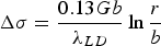


The Orowan–Ashby equation for a random distribution of impenetrable particles goes by the form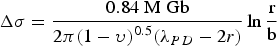


This derivation of the Orowan–Ashby equation provides a better estimate of particle strengthening that the shear resistant particles in PH and DH will provide to the matrix. However, there are also a variety of other mechanisms that might be active depending on alloy composition.
The strengthening contribution from matrix grain size is described by the Hall–Petch mechanism, given in Equation (5)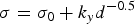


Rapid solidification broadly describes methods with cooling rates on the order of 102–1012 K s−1 that form unique microstructures with non-equilibrium phases and structures [9,31]. Rapid solidification is often used to produce fine matrix grains and particles, but these have inherently high interfacial area, and consequently a large interfacial energy contribution to the total free energy and will readily grow unless they form in a stable configuration or are resistant to coarsening. Rapid solidification’s high cooling rates typically prevents time-dependent particle or grain growth, so the microstructure is often more homogenous than other methods which can help prevent particle coarsening.
Particles of different radii have differences in free energy arising from capillarity effects, providing a driving force for particle coarsening, known as Ostwald ripening, which tends to decrease the free energy of the system by forming a more homogeneous distribution of larger particles [9,32]. The free energy gradient between two particles, including grains, driving coarsening can be expressed as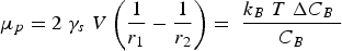


The Lifshitz–Slyozov–Wagner (LSW, formerly referred to as Lifshitz–Wagner) theory provides a better understanding of particle size development as the following derivation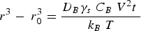


Conductivity
Strengthening copper can be readily achieved by adding a secondary phase or solute, but if thermal conductivity is a critical design property, such as the case with the SSME combustion chamber liner or high-heat-flux applications, the alloy choice becomes significantly more complex. The principles of conductivity in metals will be discussed to help understand alloy choice and relationships between thermal and electrical conductivity.
Thermal energy is often attributed to atomic vibration in a given material, but a solid’s vibration can further be defined by quantum mechanics as a wave carrying vibrational energy between the lattice or a phonon [34]. All crystalline materials conduct thermal energy through phonon interactions such as lattice or phonon thermal conductivity, 
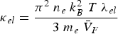
One of metals’ unique qualities is the presence of free conduction electrons that readily transfer and serve as point charge entities for charge and heat which collectively contribute to electronic thermal conductivity, 


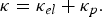


Copper, silver, and gold each have a half-filled 4s conduction band that is highly mobile and permissible to electronic transfer. Since electrical conductivity is a direct measure of electron transport, this accounts for their high conduction. Thermal and electrical conductivity are intrinsically linked as both are measurements of the ease of transport of energy; thermal conductivity is under the influence of a thermal gradient, and electrical conductivity is under an applied electric field. Additionally, the Wiedemann-Franz-Lorenz law, shown in Equation (11), provides a relation of electrical conductivity, σ, to thermal conductivity, κ, and temperature, T
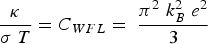
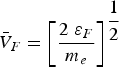
Equation (9) predicts the electronic contribution to thermal conductivity will increase with temperature, if mean free path, 

Prediction of phonon and electron interactions are limited, so the mean free paths of electrons, 


Thermal expansion
Alloy choice for a high-heat-flux application like combustion chamber liners must also consider thermal expansion alongside mechanical strengthening and conductivity. Thermal expansion in the combustion chamber liner contributes the majority of the stress and strain by the presence of high thermal gradients in the liner’s wall rather than mechanical sources [2,19]. The material’s coefficient of thermal expansion and can be calculated volumetrically using Equation (12) or linearly by exchanging the volumetric terms for length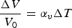
Analysis of the thermal strain and distribution was conducted by Andrus and Bordeau [19] of Pratt & Whitney on NARloy-Z liners with nickel close-outs, demonstrated in Figure 4, in 1989 which were used on the SSME revealed hot-wall temperatures ranging from 477 K in the nickel close-out to over 977 K in the liner [19]. The nickel close-out has lower thermal expansion and operating temperature which radially restrains the hotter NARloy-Z liner which demonstrated a tendency to expand radially outward [19]. During a single cycle of operation, the restraint of the nickel close-out generates compressive thermal loads in the hoop direction followed by relaxation during shutdown [19]. Channel thinning or dog house effect failure mode development of combustion chamber liners in order of progression and top view, not to scale; redrawn/modified from [1].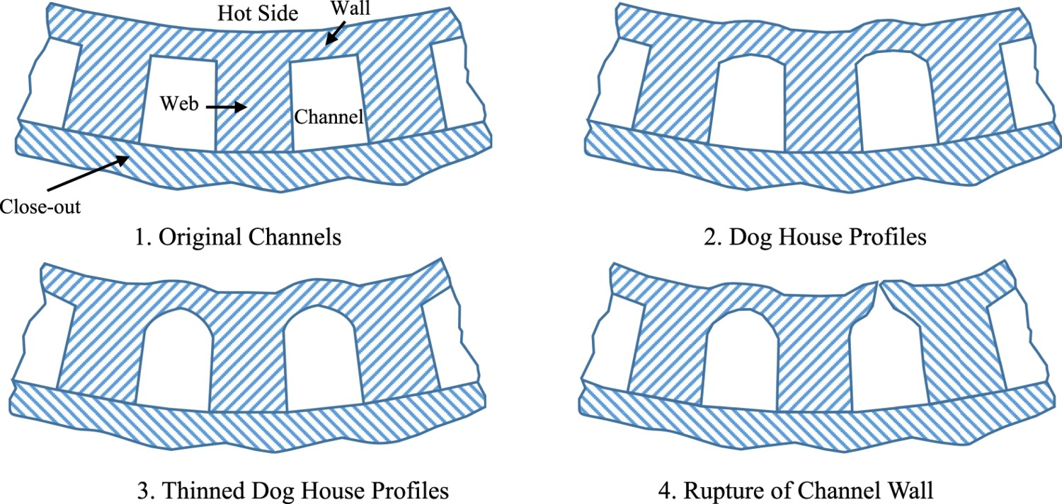
Rupture, fatigue, and creep
The combustion chamber liner’s complex geometry and thermal loading during operation produces similarly complex stress and strain throughout the liner. As a result, predicting failure in the SSME was challenging and sources of failure were used to better understand alloy design and implementation. The main mechanical failure in the nozzle of rockets is rupture of the cooling channels from wall thinning and is referred to as the ‘dog house’ effect due to the profile that the originally rectangular channels assume over time, shown in Figure 4 [19,39]. In Figure 4, the web, also called the rib or land, separates the cooling channels, and the wall separates the channel from the hot side. The close-out chemistry varies depending on the fabrication methods, and the thickness of the wall depends on fabrication limitations. The wall separating the cooling channel and hot side of the liner was observed gradually deforming without material loss over operating cycles and eventually rupturing when sufficient biaxial ductility was lost [19]. Wall thinning is a complex failure mode that has been the subject of debate and has been attributed to different forms of fatigue and creep with dominant mechanisms dependent on geometry, alloy choice, and liner environment [19,39,40]. Better understanding each of these contributions to wall thinning led to better designs throughout the SSME’s lifetime and into new rocket design.
Fatigue is a failure mode that occurs when a material is subjected to repeated cycles of stress and accumulation of plastic strain. The number of cycles to failure or fatigue life is dependent on the magnitude of the applied stress. High-cycle fatigue involves low applied strain in the elastic regime that takes a long time to initiate failure, often above 10,000 cycles [23]. By contrast, low-cycle fatigue (LCF) is caused by relatively high plastic strain that initiates failure below 10,000 cycles [23]. If the source of strain is from thermal expansion and generates plastic strain, it is referred to as low-cycle thermal fatigue (LCTF) and is one of the dominant failure modes of high temperature structural components [41]. Under the original design constraints presented by Cook and Coffey, the SSME combustion chamber liner would require a fatigue life of at least 400 cycles at 700–900 K [17]. If the strain exceeds elastic limits, plastic strains accumulate in the liner during each cycle, producing LCTF [19].


Characteristics of common particles used in strengthening Cu and Cr2Nb, GRCop alloys’ strengthening phase, with Cu for comparison.
*Average of reported values.
** C15 Cr2Nb transforms to C14 above 1858K and melts congruently at 2043 K based on the Cr-Nb phase diagram in Figure 5(c).
Creep is associated with progressive deformation as a function of time under applied stresses at constant temperature [23,42,43]. Creep can occur over a wide range of temperatures and stress levels and has multiple mechanisms responsible for progressive plastic deformation mostly based on diffusion and dislocation motion. Although the operating time of each cycle is short, creep can accumulate between cycles in a phenomenon called cyclic creep if the thermal strain is high enough [44]. Another creep term that is often attributed to failure in the combustion chamber liners is creep ratchetting which is accumulated plastic deformation specifically from unequal tensile and compressive loading and incomplete stress–strain loops in temperature cycling [45]. The rate of ratcheting and wall thinning strongly depend on the degree of heat flux and channel geometry [46].
During the Space Shuttle’s operation, the cooling channel geometry and cooling efficiency were better optimised with improved machining, fabrication, and prediction technologies which significantly reduced the concern of the dog house effect [47]. Regardless of improvements, wall thinning from LCF and creep remain a concern for future designs and effort should be made to separate the effects of creep and LCF if the hot-wall temperature is high enough to facilitate creep.
Environmental resistance
The thrust chamber environment has serious hydrogen embrittlement and blanching concerns due to high temperatures and the mix of liquid H2 and O2 fuels undergoing combustion that can cause failure in the liner if left unchecked. Other examples of detrimental environmental effects include orange peel roughening and cracking at inclusions but have been more easily detected, prevented, and understood [19].
Hydrogen embrittlement is largely dependent on the alloying elements in the Cu liner since Cu’s crystal structure is FCC which is not susceptible to H embrittlement [48]. BCC and HCP metals are susceptible to H embrittlement, but only if they are present as separate phases. NARloy-Z has demonstrated adequate H embrittlement resistance despite its Ag (BCC) and Zr (HCP) content because Ag and Zr are either in solid solution or as an intermetallic compound, further described in Table 2 [49,50].
Blanching is thought to be caused by oxidation–reduction cycles initiated by fluctuations, caused by hot spots in the geometry or the eventual degradation caused by constant combustion cycling during operation, in the oxygen–hydrogen fuel system. Blanching is represented by surface discolouration and corrosion of the liner wall and has been observed preceding channel wall failure in failed NARloy-Z chambers [19,51,52]. Inspection of blanched regions of NARloy-Z chambers revealed pits, cracks, fissures, and sponge-like appearance which damages the thin-walled coolant channels which roughen and decrease their cooling efficiency [48]. Unlike H embrittlement, blanching has been the primary cause of failure in NARloy-Z liners and rocket engines in general [52]. This may appear to contradict with wall thinning as the primary failure mode, but blanching has been observed proceeding wall thinning and is likely a strong contributor due to how it impacts the surface.
Various researchers have proposed and experimented with thermal barrier coatings (TBCs) to improve the thermal resistance and reduce blanching of the chamber liners, turbine blades, and other SSME hardware [47,53–59]. TBC’s are a thin coating of a low thermal conductivity material such as ZrO2, ZrO2-Y2O3, and NiCrAlY (used as a bond coating) that can reduce surface oxidation, improve corrosion resistance, and lower the temperature of the substrate on the hot side of a thermal gradient [56,57]. TBCs could significantly lower thermal strain have been estimated to improve the life of a combustion chamber liner by a factor of 3–30 [46]. While TBCs with NiCrAlY were applied to the turbine blades of the SSME, it doesn’t appear that any were used on the NARloy-Z liner due to issues of coatings failing to retain adherence to the liner and spalling or flaking after repeated thermal cycles [53,58]. During the coating of TBCs, the copper substrate (NARloy-Z) would oxidise and the coating would develop compressive residual stresses that formed a rough coating surface that performed poorly [53]. Various groups like Butler and Pindera have attempted functionally grading the TBC into combustion chamber liner alloys to improve cohesion, but the barrier’s effectiveness decreases when the chemistry is altered [59].
Development of Cu-rich Cu–Cr–Nb Alloys
Relevant phase diagrams and Cr2Nb
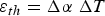
While NARloy-Z was used successfully on the SSME, researchers were looking for and developing alternatives with better long-term properties and overall reusability. Ellis and Michal of Case Western Reserve University formulated Cu alloys with additions of Cr and Nb in the 1980s as candidate SSME liner alloys in collaboration with NASA Lewis Research Center (LeRC and now NASA Glenn Research Center) [9]. At this time, limited to no Cu–Cr–Nb alloys had been developed or publicised [9]. During a phone interview in March 2020, Dr. David Ellis explained that the original idea for the project was conceived by then-Branch Chief Dr. Tom Glasgow of NASA LeRC who demonstrated that chill block melt spinning (CBMS) could be used to form desirable Cu–Cr–Nb alloys [60]. Glasgow then used a NASA graduate fellowship to bring Ellis and his graduate advisor, Dr. Gary Michal, onto the project and conduct more thorough alloying and characterisation [60]. CBMS’s high cooling rates were leveraged in an attempt to form a supersaturated solid solution with Cr and Nb. The supersaturated solution could then theoretically be precipitation hardened by the formation of a stable Cr2Nb intermetallic that would provide similar strengthening methods compared to NARloy-Z’s Ag and Zr. The intermetallic was expected to have a low solid solubility which would enhance conductivity of the matrix and provide a hard precipitate resistant to shear and coarsening effects [60]. The majority of Ellis and Michal’s decisions and hypothesis on the new alloy were based on the best available alloys and limited available literature including the Cu–Cr, Cu–Nb, and Cr–Nb phase diagrams, shown in Figure 5.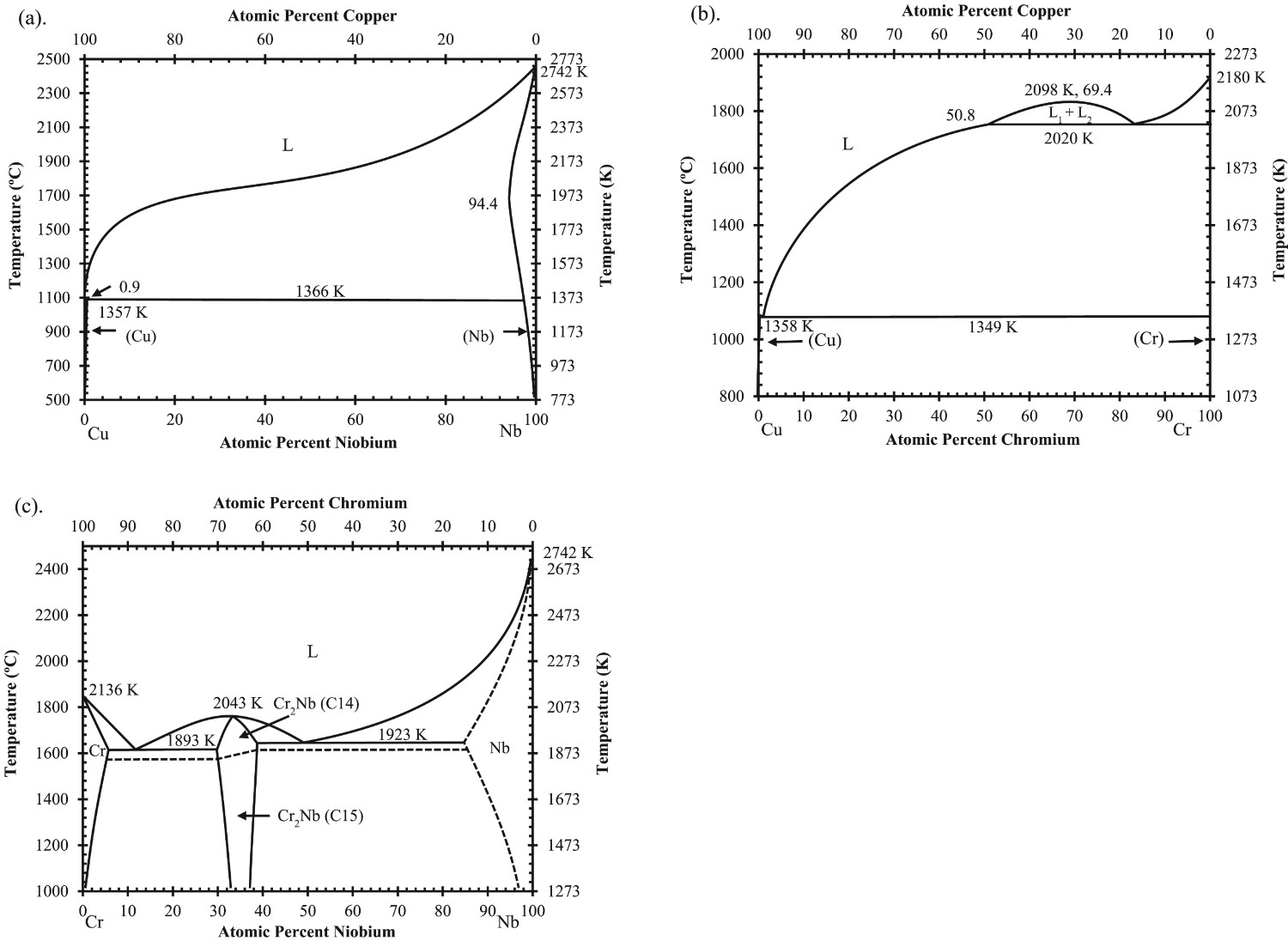
At the time to their knowledge, no ternary phase diagram was available, however, a Russian article by Nikolayev and Rozenberg presented ternary phase diagrams and a quasi-binary Cu–NbCr2 phase diagram from 1972 which they were likely unaware of at the time [9,61]. The existence of a binary Cu–Cr2Nb phase diagram was important to Ellis and Michal because they inferred that an intermetallic Cu–Cr2Nb phase might form from substitution of Cu for Cr, although no such intermetallic has been observed [9]. Michal later calculated a Cu-rich pseudo-binary phase diagram, but it would remain internal until it was presented by Anderson without additional context or details regarding its calculation [62]. It would not be until 2009 that Liu et al.’s [63] experimentally and thermodynamically calculated phase equilibria provided thorough ternary phase information on Cu–Cr–Nb and a binary Cu–Cr2Nb phase diagram, presented in Figure 6, covering the full range of Cu which agreed with Nikolayev and Rozenberg’s work [61]. However, the binary phase diagram in Figure 6 does show a solid solution gradient with temperature that will allow for precipitation strengthening. The maximum solid solubility of Cr2Nb is less than 1 wt-% at the solidus (or on final solidification), and it continues to decrease with temperature allowing for more precipitation that can be enhanced with supersaturation. Calculated binary Cu–Cr2Nb phase diagram and Cu-rich insert calculated by and redrawn from [1].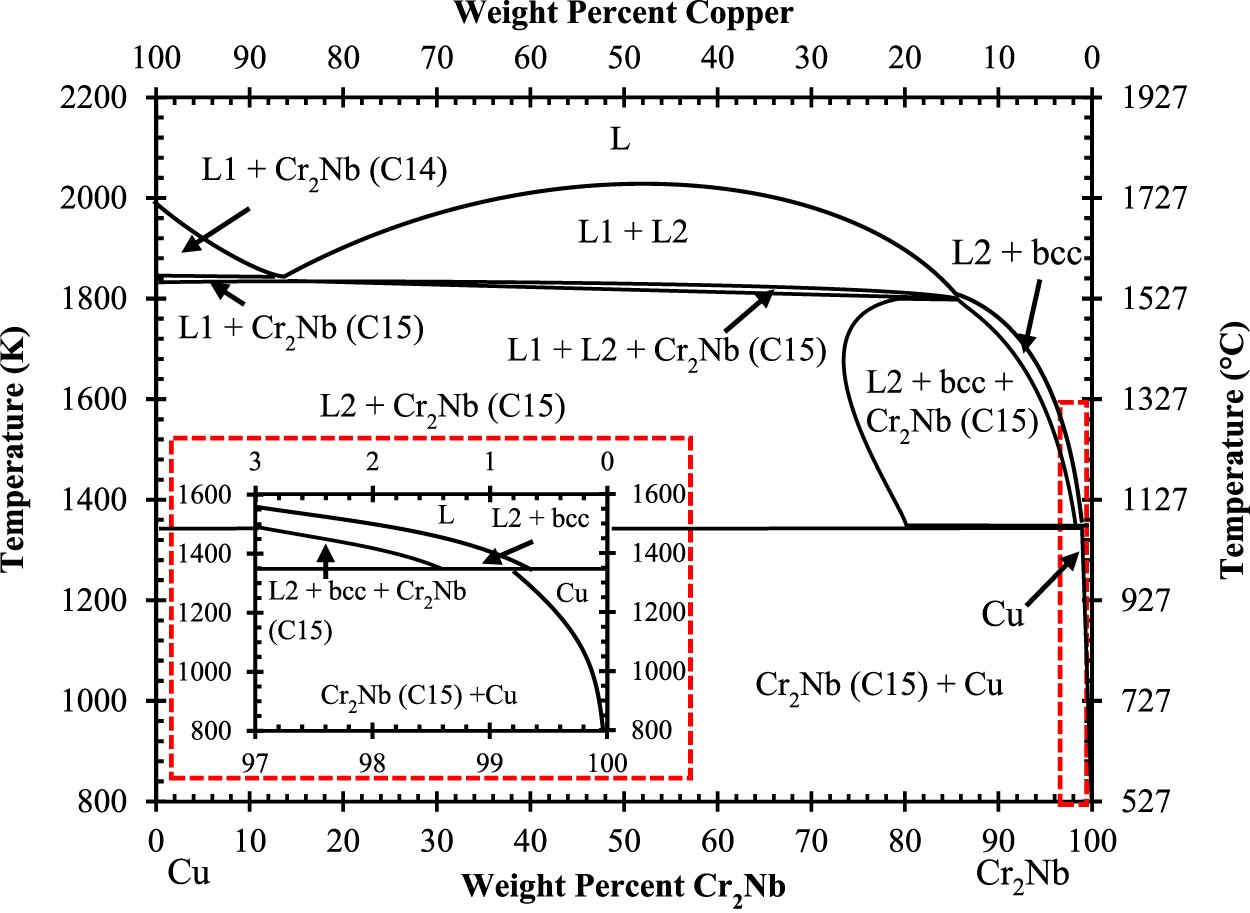
The Cr–Nb phase diagram, shown in Figure 5(c), shows that the intermetallic Cr2Nb phase has two polymorphs. Since the intermetallic has an AB2 stoichiometry, they both belong to what are commonly referred to as ‘Laves’ or ‘Friauf-Laves’ family of phases [64]. The older Cr–Nb phase diagram presented is likely outdated but was the newest available to Ellis and Michal during development. Based on the phase diagram of Figure 5(c), Cr2Nb solidifies first as the hexagonal C14 Laves phase or MgZn2 structure type and transforms to the cubic C15 Laves phase or Mg Cu2 between 1893 and 1923K [64,65]. The existence of the C14 phase in the Cr–Nb phase diagram has been brought into question with some researchers concluding that it is a metastable phase [66]. These arguments are summarised well by Jiang et al. and seem to be a matter of current debate, and our focus will be on C15 Cr2Nb and Figure 7 shows its crystallography [67]. Crystal structure of the Cr2Nb cubic C15 Laves phase drawn from atomic coordinates from [1]: (a) 2 dimensional sequential stacking orientation with atom layers representing positions, modified partially from [2], with dotted line representing one unit cell; (b) unit cell of C15 Cr2Nb; (c) extended two dimensional (001) projection.
The Nb atoms in C15 Cr2Nb are arranged the same as the zincblende structure, though with only Nb instead of with Zn and S, and the smaller Cr atoms fill every available tetrahedral interstitial site. This structure is fairly stable, but from a temperature perspective, Cr2Nb is not as stable as Al2O3 or other oxides with melting temperatures ranging from 2100 to 3400 K, some of which are shown in Table 4 [36]. Cr2Nb melts congruently at 2006 K, well above the hot-wall temperature of 700–900 K and was assumed to have limited diffusion and interaction with Cu, which was based on the existing phase diagrams and results of Cu–Cr and Cu–Nb alloys [9,68–70]. Low solubility and diffusivity of Cr and Nb in liquid Cu reduces the likelihood of Cr and Nb in solid solution, and results in the formation of most of the Cr2Nb during solidification and general coarsening behaviour. C15 Laves phases are known to be brittle at ambient temperatures and are currently commonly paired with a ductile matrix to leverage their high strength at high temperatures, but during the time of Ellis and Michal’s work, it seems that the general focus was more on integrating ceramic particles [9,22,36,64].
Initial chill block melt spinning alloying
Ellis and Michal tested a range of stoichiometric Cr2Nb or 2:1, Cr:Nb atomic ratios balanced by Cu including 2:1, 4:2, 6:3, 8:4, and 10:5 [9]. The 10:5 ratio was expected to be an over-alloyed condition that would form an incomplete solid solution, and 2:1 was set as an arbitrary minimum [9]. Master alloys in these ratios were first produced by induction melting and casting, then re-melted and solidified into ribbons and flakes by CBMS under an Ar atmosphere with a chilled Cu wheel [9,71,72]. Although commonly used for producing bulk metallic glasses, CBMS is useful for testing small volumes and can yield high cooling rates of 105–106 K s−1 under optimum conditions [31]. Some of the ribbons were consolidated for by vacuum hot pressing at 124.2 MPa and 923 K for 1 hr [72].
Examination of the induction melted alloys using X-ray diffraction and optical microscopy showed evidence of a largely pure Cu matrix with large, centimeter-sized FCC Cr2Nb precipitates [9]. Cr precipitates were expected to be present but were not detected [9]. Using transmission electron microscopy (TEM) and select area diffraction (SAD) to interrogate the CBMS produced ribbons, Ellis and Michal asserted that Cu matrix was largely pure with distinct Cr2Nb particles in the HCP C14 phase with no evidence of bulk metallic glass formation [9]. In the available literature for Cu–Cr–Nb alloys, CBMS is the only case where C14 has been detected which is likely the result of the extreme cooling rates. Differential thermal analysis was run in an attempt to detect the transformation between C15 and C14, but the results were inconclusive [9]. Microstructural characterisation of the various ratios showed the 2:1 ratio ribbons’ had long, columnar grains, the 8:4 and 10:5 had fine, equiaxed grains, and the 4:2 and 6:3 ratios had mixed grain morphology [9]. The Cr2Nb precipitates were small and on the order of 10 nm for all of the alloy ratios which is unusually small and likely due to the rapid cooling rate. Additionally, the precipitates demonstrated limited coarsening by only growing to 20.6 nm after aging at 773 K for 100 h [9]. Nb precipitates were not detected in any of the samples [9].
The work by Ellis and Michal was successful in developing a new alloy with high mechanical and thermal stability. However, their mechanical and thermal property results are not comparable to current production properties due to variation in the processing methods. In this initial study, many important concerns were voiced that would be addressed in later studies with focus given to the 8:4 and 4:2 Cr:Nb ratios based on their preliminary performance. The 8:4 and 4:2 ratios have experienced the most development and were eventually given the commercial designations ‘GRCop-84’ and ‘GRCop-42’ representing Glenn Research Copper alloy and their respective ratios in the early 2000s by Dr. Michael V. Nathal of NASA GRC to represent the GRC’s efforts in developing the alloy [60].
Following their preliminary work, Ellis and Michal performed extensive testing on the 8:4 and 4:2 Cr:Nb ratio alloys and directly compared NARloy-Z fabricated and tested under the same conditions in 1996 [26]. Instead of alloying with CBMS, both GRCop alloys were first alloyed by gas atomisation, hot-extruded into cylindrical bars at 1130 K, and tested in the as-extruded condition with no additional heat treatments [26]. Thermal conductivity, yield strength, UTS, LCF, and creep were extensively tested and the results of these tests provided statistically significant evidence that the GRCop alloys’ properties were a viable replacement option for combustion chamber liners or other high-heat-flux applications.
Difficulties of comparing high-heat-flux Cu alloys
High-heat-flux Cu alloys are difficult to compare because of concerns with conductivity and the condition of tested specimens including heat treatment history, exact chemical composition, and testing equipment. Conductivity is a critical design consideration and dependent on the microstructure and processing conditions, but few studies measure conductivity due to lack of equipment or time constraints. In order to provide an accurate representation of an alloy’s properties for comparison, the best available processing condition should be used with testing conducted under the same standards and testing conditions for each individual alloy. Under ideal circumstances, thermal and mechanical measurements should be made on the same batch of samples with descriptions of processing conditions. It is problematic to show thermal conductivity and mechanical strength as a function of temperature for alloys with different thermal histories due to the strong microstructure dependence of conductivity. Comparisons of creep and LCF can be particularly difficult since considerable time is required to collect data, and there is a considerable range of stress and temperature conditions that are rarely consistent between experiments.
Experimental or literature-based comparisons of high-heat-flux Cu alloys including NARloy-Z, GRCop-84, GRCop-42, GlidCop, and AMZIRC for nuclear reactors or rocket nozzle hardware have been conducted by various researchers [2,4,6,15,46,73–78] that are each valuable for their particular trends and observations. The majority of the reference-based data used to compare NARloy-Z, GlidCop, or AMZIRC can be traced to a series of experiments by Conway et al. of NASA LeRC in the 1970s, and new, high-quality data is needed for better comparisons [75–77]. Arguably, the best and most current comparison is de Groh et al.’s 2008 publication [78] which compares GRCop-84, AMZIRC, NARloy-Z, GlidCop Al-15, Cu-1Cr-0.1Zr, and Cu-0.9Cr. Each alloy was produced to current standards in the same geometry, subjected to the same heat treatment, tested under the same conditions, and compared for performance as high-heat-flux alloys, with the exception of NARloy-Z which used existing data [78]. Microstructures, thermal expansion, elongation, yield strength, reduction in area, and general creep properties as a function of temperature are presented [78]. However, GRCop-42 and more current processing methods of GRCop-84 are not included in the comparison, and thermal conductivity data was not collected which should have a significant impact on the comparison. Tests could be done with new material under the same conditions to add to the comparison but results may differ, hopefully only minor differences, due to changes in equipment or operator. In the case of GRCop alloys, processing conditions have changed dramatically over time, and limited data has been published, so a comprehensive comparison of processing conditions is challenging. The following sections will instead focus on the literature available for GRCop alloys, and comparisons to similar high-heat-flux alloys will prioritise de Groh et al.’s data when possible.
Processing, microstructure, and properties of Cu-rich Cu–Cr–Nb alloys
Fabrication of GRCop alloys
One of GRCop alloys’ largest limitations is that they cannot be solidified by methods with low cooling rates like conventional casting for high-heat-flux applications. Cr2Nb will form large precipitates over 1 cm in diameter, exceeding those shown in Figure 8(b), that will not aid in mechanical strengthening or retention of conductivity [2]. Serviceable GRCop-84 hardware has been produced by a variety of fabrication and post-processing techniques but is typically first alloyed in a melt and solidified into bulk powder by gas atomisation with Ar. Micrographs of GRCop-84; (a) Gas atomised powder showing pure copper matrix with Cr2Nb particles represented by the grey phase [1]; (b) Typical cast microstructure showing large, elongated Cr2Nb [2]; (c) Etched, as-extruded with visible matrix grains and Cr2Nb particles and agglomerations represented by the lighter phase [1]; (d) Extruded microstructure after 1273 K exposure for 30 min demonstrating more visible grain and particle boundaries [1], adapted with permission.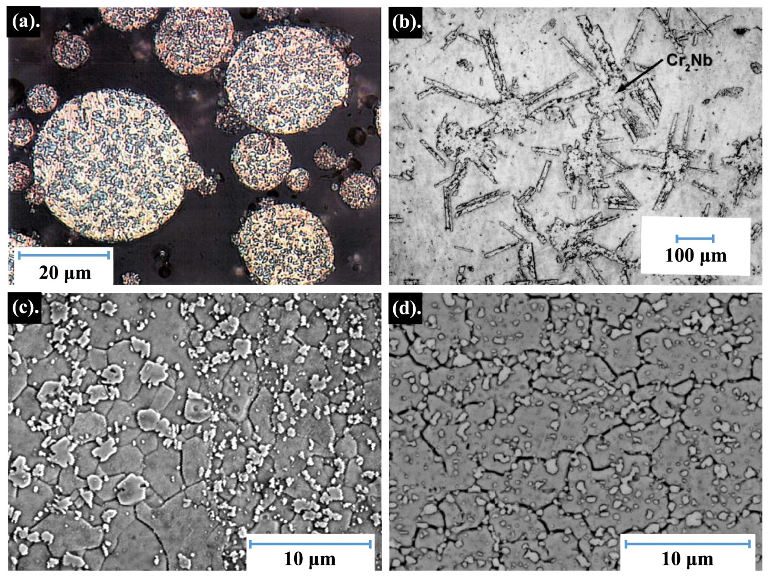
The resulting powder has a fine distribution of Cr2Nb precipitates in powder particles visible in Figure 8(a) [2,79]. While other rapid solidification techniques could be used to produce fine microstructures, gas atomisation is more affordable and produces powder with high purity and consistency. Gas atomisation is a rapid solidification technique where a liquid metal stream is reduced to small particles by gas jets and is often used for its high production volume and relative cost. The number of jets and configuration can vary, but gas atomisation consists of three primary stages: breakup of a liquid metal stream, secondary breakup of large molten droplets, and solidification of the final small (10–100 μm) powder particles [80]. When gas is used, the breakup of the liquid metal stream occurs above the focal point of the gas stream as a result of a vacuum generated by the gas streams’ pressure, which helps improve the efficiency of the secondary breakup [80]. Depending on cost and reactivity with the metal, gasses like Ar or N2 are used, forming smooth, spherical particles from the liquid stream [80]. Water and steam are inexpensive but form more irregular shapes with high oxide content, so these methods are used primarily for low and high alloy steels [80,81]. Standard gas atomisation with inert gas has a lower cooling rate of 102–103 K s−1 compared to CBMS, while supersonic and close coupled gas atomisation techniques have cooling rates comparable to CBMS [9].
GRCop-84’s gas atomisation specifications are fairly strict to help preserve the thermal conductivity of the end product and are partly listed by Gradl et al. [82]. High purity of the raw materials is critical to minimise Fe and O contamination, shown by Ellis to have a significant impact on the performance as shown in Figure 9 [2]. According to Gradl et al., GRCop-42 is simpler to produce through gas atomisation compared to GRCop-84 based on anecdotal evidence from powder suppliers. The alloy will react with N2 and form nitrides, so Ar is necessary for gas atomisation and should be used to backfill containers to minimise oxygen exposure. Additionally, a slight off-stoichiometric excess of Cr is added to suppress Nb precipitate formation and H embrittlement concerns ranging from 2.02 to 2.05 Cr/Nb based on powder compositions presented in Table 2. Cr precipitates are expected to be present but are often difficult to detect due to their small size and quantity.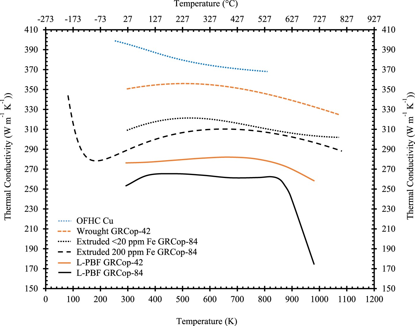
Following powder production, most powder metallurgy and welding techniques can be applied to GRCop alloys without issue as well as warm and cold rolling, bump forming, stamping, metal spinning, and tube drawing [2]. NASA has demonstrated GRCop-84 consolidation methods including direct extrusion, hot isostatic pressing (HIP) to form, and vacuum plasma spraying (VPS) into shape and densifying with HIP [2]. NASA has also demonstrated a variety of welding techniques including diffusion bonding, inertia welding, friction stir welding, electron beam welding, and brazing, but limited information on these techniques is available currently [2,83,84]. Combustion chamber liners of GRCop-84 have been produced by VPS, conventional wrought processing, and by powder bed additive manufacturing (AM), with AM proving to be the most versatile processing technique [82,85]. The term ‘wrought’ is used in GRCop literature to represent conventional processing methods like extrusion or rolling and the terminology used by the original authors will be maintained. Fabrication of GRCop-42 has been demonstrated with several techniques including hot extrusion and AM, any methods that work with GRCop-84 should be viable with GRCop-42. The specifications of extrusion, HIPing, and commercial rolling are detailed by Ellis et al. [86].
Before AM, several concepts were available for fabricating new liners and nozzles with GRCop alloys to improve SSME designs. These are described by Ellis et al. [86] and include metal spinning plate, directly HIPing into a cylinder or hourglass shape, diffusion bonding platelets, and forming tubing, but these processes all require considerable machining to produce cooling channels which are intrinsic to the operation of the liners. Annealing and cold work have a demonstrable effect on the room-temperature tensile properties, but Ellis et al. showed that recovery and recrystallisation occurs between 473 and 873 K depending on the degree of cold work, so the benefits of cold work will be lost in high-heat-flux operations [86]. At temperatures where cold work could improve GRCop-84’s mechanical properties, other alloys with more optimal properties should be considered.
Additive manufacturing
Cu alloys present two main challenges with powder bed AM: reflectivity with conventional lasers and high thermal conductivity of the powder [87]. Copper has high reflectivity with infrared light (1 μm) used in conventional lasers, so the majority of the energy used by conventional laser additive systems will not be absorbed by Cu powder and can inhibit melting. If sufficient energy is absorbed to initiate melting, the melt zone will have high local thermal gradients that will either inhibit melting or cause delamination, layer curling, and build failure [87]. A review of AM of pure Cu has been published by Tran et al. on selective laser melting (SLM), electron beam melting, binder jet, and ultrasonic AM [87]. Green lasers, which have a shorter wavelength of 515 nm, have been used for Cu with laser-based AM, but they are more expensive and less common [87].
As Gradl et al. discuss, GRCop-84 is unusual because it is easily melted by conventional SLM, a form of laser-powder bed fusion (L-PBF) AM [88]. As the more generic term, L-PBF will be used to represent sources that reference SLM. Gradl et al. postulate that the presence of the Cr2Nb precipitates is responsible for initiating melting by lowering the initial reflectivity of the powder [88]. Cu’s reflectivity decreases rapidly with temperature, so as long as enough initial energy can be absorbed, melting should initiate [88]. Additionally, the thermal conductivity is reduced by the high alloying content which likely contributes to the ease of AM by reducing heat dissipation. GRCop-42 has been shown to have a similar affinity with conventional L-PBF [82]. Measuring the reflectivity of the GRCop alloys would likely provide evidence to support their relative ease of AM.
Additive manufacturing often results in inherent porosity, anisotropy, and reproducibility concerns that must be addressed before implementation. Post-production annealing and HIP, often standard on aerospace hardware, are usually sufficient to ensure near theoretical density and homogeneity [88]. NASA’s L-PBF development of GRCop-84 and GRCop-42 has progressed to the point where L-PBF build parameters have been established and practical hot-fire tests of L-PBF GRCop liners have been performed [82,88]. NASA has demonstrated GRCop-84’s versatility with L-PBF in forming combustion chamber liners and was a key component of the low-cost upper stage propulsion (LCUSP) project [10,85], but the majority of NASA’s build parameters and characterisation efforts are internal and not currently available to the public. However, Gradl et al. mention that process parameters and characterisation data are available to industry to expand NASA’s supply chains, and that their GRCop-42 L-PBF process parameters are different than GRCop-84 [89].
A technical memorandum by Cooper et al. [90] provides NASA’s basic process parameters for GRCop-84 and initial parameter testing for GRCop-42 on a ConceptLaser M2 system though the focus of the memorandum is on GRCop-42, and the parameters may not be current. Their ConceptLaser uses a single 400 W Nd:YAG laser with a spot size of 52 μm, travel speed of 50–5,000 m s−1, and the build chamber is filled with Ar [90]. The default parameters for GRCop-84 include a core laser power of 180 W, core scan speed of 800 mm s−1, hatch width of 0.105 mm, build layer thickness of 0.03 mm, and core energy density of 95.2 J mm−3. The coolest, fastest parameters in this memorandum for GRCop-42 are 270 W, 1,025 m s−1, 0.099, 0.045 mm, and 59.1 J mm−3 in the same order as the parameters for GRCop-84 [90]. Cooper et al. were able to improve on the build parameters of GRCop-84 by successfully increasing the build layer thickness and scan speed which improves the print time by about 20% [90]. Characterisation work by Hayes et al. provides some general metallography and mechanical properties of L-PBF GRCop-84, and computed tomography of small-scale L-PBF GRCop-84 liners including demonstration of a new cooling channel design and orientation that can be achieved by AM, but more thorough characterisation is necessary for future development [85]. The design freedom allowed by AM for the cooling channels provides a strong motivation to pursue AM as GRCop alloys main method of fabrication for high-heat-flux applications in the future.
Microstructure of wrought GRCop-84
There are few microstructure-focused studies available for GRCop alloys with the exception of gas-atomised powder and extruded GRCop-84, the majority of which have been contributed by Groza and Anderson [29,30,62,79,91]. While there are newer fabrication methods available, such as AM, the available literature is developing, so gas-atomised powder and extruded GRCop-84 are the best available representation of the alloy and should be comparable to newer methods.
Groza and Anderson investigated the microstructural features of gas-atomised GRCop-84 powder which had a powder particle size of less than 106 μm [79]. The powder used in this study is not directly comparable to current gas-atomised powder used for powder bed AM which has a powder particle size of 25–40 μm, shown in Figure 8(a), but the general precipitate distribution and trends are comparable. The more current powder of Figure 8(a) is used as a visual reference for Groza and Anderson’s work because it is the best available micrograph which shows distinct separation of the Cu matrix and Cr2Nb particles, but it is not the same powder. Groza and Anderson identified a bimodal distribution of primary and secondary Cr2Nb precipitates on the order of 1 μm and 10-100 nm, respectively [79].
Groza and Anderson suggest that the primary particles solidify and grow rapidly during atomisation before the surrounding Cu matrix can solidify which yields large primary particles [79,91]. The primary particles are irregular in shape, which can be observed in the more current powder of Figure 8(a), from their lack of constraint in the liquid and serve partially as nucleating sites for the Cu matrix. The secondary particles are hypothesised to precipitate out of the matrix grains because the secondary particles are primarily observed within the matrix grains and the matrix should be supersaturated considering the cooling rates [79,91].
The bimodal distribution observed in the gas-atomised powder persists in extruded GRCop-84, shown in Figure 8(c,d). The average diameter and distribution of the primary and secondary particles in the extruded material remains roughly the same as the powder [92]. This demonstrates that the starting powder microstructure has a significant impact on the final microstructure, so powder quality and optimisation might improve the final microstructures. Both the primary particles and Cu matrix grains had limited coarsening behaviour during heat treatments which is ideal for high temperature performance. Following aging treatments at 773 and 973 K, below the Cu-Cr2Nb solvus temperature (see Figure 6), further precipitation was observed in the extruded material as a distinct secondary distribution of particles which indicates that the matrix is supersaturated [92]. Even after an aging of 1323 K for 100 h, the mean primary precipitate diameter only increased from 0.93 ± 0.04 to 1.35 ± 0.03 μm, where the ± represents standard error [92]. This is consistent with statements that the coarsening of Cr2Nb is slow in GRCop-84.
Anderson et al. estimated the strengthening contribution of the primary and secondary particles using the Orowan-Ashby equation for a random distribution of impenetrable particles (Equation (3)) [92]. The primary particles were found to contribute little to strengthening based on estimates of the Orowan-Ashby equation, while the secondary particles provided a high degree of strengthening. However, the large particles contribute to grain boundary (Hall-Petch) strengthening by pinning the matrix grains and preventing grain growth [30], evidenced by the copper matrix grains exhibiting slow growth with a maximum size of 4 from 0.9 μm in the as-extruded condition [29]. Based on particle size and stress measurements, Anderson et al. calculated the contribution of Orowan and Hall-Petch strengthening with good agreement to experimental results with Equation (3) [30]. The Hall-Petch strengthening is dominant with roughly two-thirds of the contribution to strength, and Orowan contributes roughly one-third, contrary to prior estimates [30]. This appears to reveal the true strengthening nature of the Cr2Nb precipitates and their role in the high temperature properties of GRCop-84 keeping the matrix grains small by pinning the grain boundaries and preventing coarsening while keeping the matrix as pure as possible for high conductivity. This strengthening ratio has been cited for newer fabrication methods but has not been reproduced and should be reevaluated for the new microstructures.
Room-temperature properties of GRCop alloys
Room temperature properties of GRCop alloys including some mechanical brazing data and some SLM GRCop-84 and GRCop-42 data; all data is from the indicated references and should be considered approximate due to limited statistics.
* Brazed at 1208 K.
i <20 ppm Fe interpreted from graphical data.
ii 200 ppm Fe interpreted from graphical data.
+ Theoretical density range based on powder alloying composition of Table 1, measured density not available.
++ Calculated from temperature dependent equations at 300 K.
Alloys used at high temperatures are best demonstrated by temperature dependence, so GRCop-42 and −84’s thermal conductivity, yield strength (YS), ultimate tensile strength (UTS), creep, LCF, and thermal expansion as a function of temperature are compared with oxygen-free high thermal conductivity (OFHC) Cu serving as the baseline example when available.
Thermal conductivity
GRCop-84’s thermal conductivity compared to similar high-heat-flux alloys is its weakest property due to its high alloying content and can be significantly impacted by impurities In 2000, Ellis and Keller with Thermophysical Properties Research Laboratory (TPRL), Inc. in West Lafayette, IN [93] calculated thermal conductivity and electrical resistivity of extruded GRCop-84 using the Kohlrausch method. Since both conductivity and resistivity are calculated, the Lorenz number could be determined and was measured between 29 and 480 K with 5 powder lots [93]. The Lorentz number was significantly higher than pure Cu’s and demonstrated a mild temperature dependence, but these results had not taken Fe impurity into account and are not accurate to current GRCop-84 chemistry. Although the Lorenz number increased, Ellis and Keller believed that this was caused by the thermal conductivity increasing and electrical resistivity decreasing in response to the material dynamically annealing during the measurements [93]. So, it is possible that the Lorenz number is constant for GRCop-84, though an updated and more accurate measurement has not been acquired. In 2005, Ellis found that Fe impurities on the order of 200–250 ppm from the Cr melt stock had a significant impact on GRCop-84’s conductivity, illustrated in Figure 9 and Table 5, and new processing guidelines ensure or require the concentration of Fe to be <20 ppm, so the mechanical properties should remain largely unaffected [2]. This distinction makes comparisons problematic with results before this publication because the Fe concentration was not commonly measured and often unknown and unreported.
Gradl et al. [12] present a significant amount of data for L-PBF GRCop-84 and GRCop-42 including thermal conductivity which is shown in Figure 9. However, the data collection method and thermal history are not presented, and they are assumed to be in the as-built condition. Both GRCop alloys have significantly lower thermal conductivity than their wrought counterparts which is likely due to a detrimental microstructural change by additive processing. This could be caused by residual stress, stoichiometry change, or dissolved content and could likely be reversed by heat treatment or HIP, so these results may not be indicative of the optimal properties. L-PBF GRCop-84’s thermal conductivity demonstrates a significant decrease starting at ∼850 K, and Gradl et al. [12] postulate that the decrease is caused by excess Cr dissolving into the Cr matrix. GRCop-42 also decreases but at a much lower rate, which is likely due to a higher degree of excess Cr. In practical application of GRCop-84, the amount of excess Cr should be optimised to reduce this effect with care taken to retain hydrogen-embrittlement resistance.
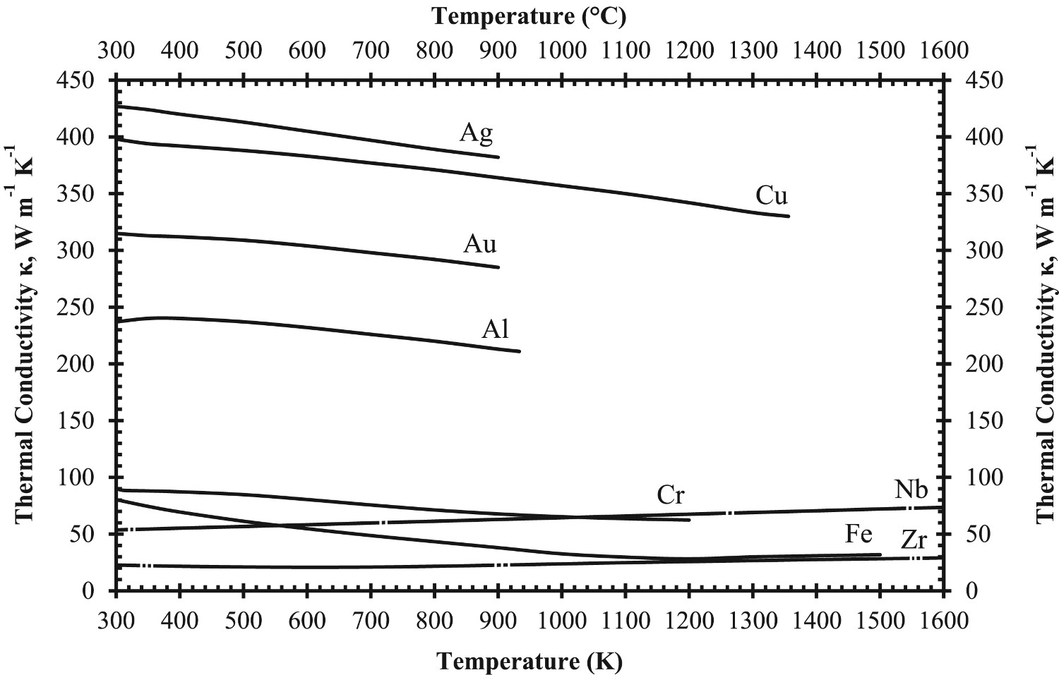
At room temperature, extruded, <20 ppm Fe, GRCop-84’s thermal conductivity is ∼76%, based on Figure 9, of OFHC’s room temperature thermal conductivity, ∼400 W mK−1 [78], while NARloy-Z’s is ∼91%. For comparison, AMZIRC has the highest available thermal conductivity of high-heat-flux copper alloys at 92.5% OFHC Cu, and GlidCop Al-15’s is approximately 80% OFHC Cu [78]. Extruded GRCop-42’s lower alloying content provides significantly fewer scattering sites, which results in a thermal conductivity ∼86.5% OFHC Cu at room temperature which is a significant improvement over GRCop-84. Extruded <20 ppm Fe GRCop-84’s thermal conductivity, shown in Figure 9, demonstrates some temperature dependence. The thermal conductivity first increases to a maximum value of ∼79.5% OFHC Cu at ∼535 K and then decreases steadily up to ∼900 K. At temperatures above 900 K, the thermal conductivity continues to decrease but at a noticeably lower rate. These regions may help identify changes in the microstructure between these temperature ranges, but this data is from a single sample and more, repeated data sets would be necessary to be certain that these shifts are not anomalous.
Tensile properties
According to Ellis et al., optimisation of tensile strength at high temperatures is not the primary design consideration of the combustion chamber liner, but tensile strength provides a readily tested macroscopic indicator of thermal stability against thermal cycling [86]. This 2012 study by Ellis et al. presents a thorough characterisation of GRCop-84 tensile properties fabricated by various methods including extrusions, HIPed billet, rolled plate, rolled sheet, drawn tube, and VPS, under a variety of heat-treatment conditions including annealed, brazed, and cold worked [86]. They reported that processing methods had a minimal effect on the tensile properties, though the HIPed billet had the worst performance, likely due to the higher consolidating temperatures and longer thermal exposures resulting in larger grain and precipitate particle sizes [86]. Regardless of processing or heat-treatment conditions, the GRCop-84 samples were noted to exhibit similar stress–strain behaviour with the exception of cold work [86].
As-extruded, annealed, and brazed GRCop-84 revealed similar general tensile behaviour, demonstrated by the as-extruded results in Figure 10, with a minimal elastic region less than 0.5% strain and long plastic region greater than 20% [86]. When the yield point is reached, as-extruded GRCop-84 rapidly reaches a stress near its UTS and remains near that stress for 10–20% elongation followed by 5–15% elongation during necking before failure [86]. Ellis et al. studied strain-rate dependence for annealed and 47% cold-worked GRCop-84 tensile specimens in a range of strain rates of 0.01–0.0008 s−1. The annealed samples demonstrated limited dependence while the cold-worked samples had some dependence [86]. Tensile data for as-built L-PBF GRCop-84 and −42 specimens, collected at room temperature, also presented in Figure 10, demonstrate significantly more brittle behaviour with a higher UTS and reduced elongation [82,86]. L-PBF samples that were HIPed demonstrate a similar tensile behaviour compared to as-extruded GRCop-84, though slightly more ductile with a ∼16–33% increase in final elongation [82,86]. In both L-PBF cases, GRCop-42 demonstrated reduced strength but longer elongations compared to GRCop-84 [82]. Stress-strain plots (tensile) (a) data collected on GRCop-84 and GRCop-42, processed using a variety of techniques with post processing treatments, and several temperatures between room temperature and 1073 K; If not specified, data was collected at room temperature [1,2]. Marshall Space Flight Center’s (MSFC) tensile specimens were fabricated on a Concept M2 SLM system, and the vendor’s were built on an EOS M400. (b) Low strain regime of as-extruded GRCop-84 data from (a) redrawn with permission.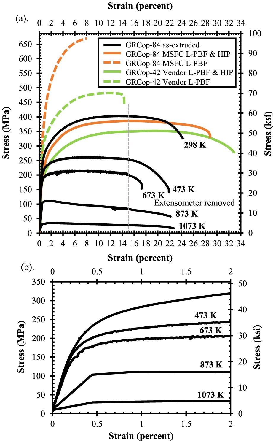
In high-heat-flux applications, changes to UTS and YS with temperature help demonstrate an alloy’s loss of mechanical strength at high temperatures. The UTS and YS as a function of temperature for OFHC Cu and GRCop-84 and GRCop-42 in a variety of conditions are presented in Figures 11 and 12. Gradl et al. discuss that the operating pressures in the cooling channel walls of combustion chamber liners can be up to 40 MPa, so the benefit of higher YS and UTS is that thinner walls can be used resulting in better cooling efficiency and lower hot-wall temperatures [82]. Similar to the thermal conductivity, the L-PBF samples are assumed to be in the as-built condition. The UTS and YS of the L-PBF samples are significantly higher, 20–30 MPa in some cases, than the wrought conditions at elevated temperatures which is a significant improvement. The improvement of mechanical properties may help balance the lower thermal conductivity at high temperatures in practical use. Below ∼873 K for YS and ∼700 K for UTS, GRCop-84’s mechanical properties are better than GRCop-42 which compensates somewhat for the shortcoming of GRCop-84’s lower thermal conductivity. Above these temperatures, GRCop-42 performs better in YS and roughly the same in UTS, which is likely caused by the comparatively weak Cu matrix dominating the strength [82].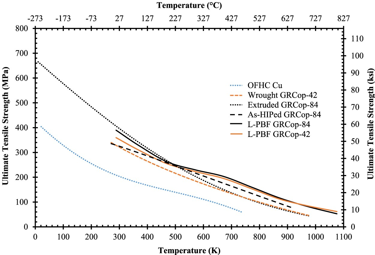
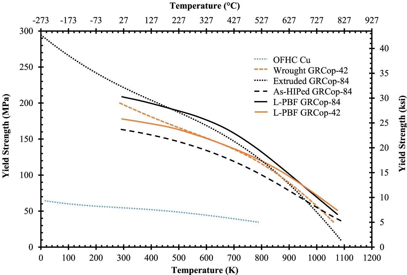
Comparison of (a) UTS and (b) YS of high-heat-flux data from [1,2] in rough descending order between 300 and 773 K and separated/reorganised at 923 K to help demonstrate the shift in strength; OFHC Cu condition is unknown, but provides baseline value; estimated from data points of figures by [1] with GRCop-84’s data based on the average of HIPed and extruded material with five tests at each temperature, and all others are estimates of two tests; OFHC Cu and NARloy-Z data estimated from trend lines [2].
* Indicates estimated and interpreted from trend lines.
**STA indicates solution treated and aged.
Creep properties and characteristics
Decker et al. in 2004 and Ellis et al. in 2015 conducted creep tests with GRCop-84 over a range of temperatures and strain rates that could be experienced by the combustion chamber liner in service [40,94]. At the time of Decker et al.’s study, the most common production methods of GRCop-84 were as-extruded or as-rolled following the extrusion, and these two forms were both creep tested [94]. The creep tests were performed in tension with a constant stress creep instrument under vacuum. A range of temperatures from 764 to 1068 K and stresses from 12.5 to 200 MPa were examined to determine the activation energies needed for creep, and analysis included applying several creep models to the results.
Ellis’s [40] creep study was more focused on liner application and generating statistically significant data to help qualify and provide to potential models predicting GRCop-84’s creep response during service while investigating the effect of processing on creep. Large and small extrusions, plate, brazed plate, production sheet, HIP billets, pre-production sheet, and friction stir welded sheet were creep tested at 773, 923, and 1073 K to determine the influence of processing on creep properties with constant load tests [40]. The creep tests were conducted in both vacuum and in air at three separate laboratories so special consideration was given to errors in their comparison. Ellis et al. focused on formulating a forward stepwise regression analysis to compare fabrication and only the power law creep model was fit to the data [40].
Typical creep curves of GRCop-84 generated by Decker et al., Figure 13(a), show three distinct regions of creep, and the strain is often in excess of 10% in contrast to dispersion strengthened alloys which usually have low ductility. Most of the strain is within the secondary and tertiary regions, with a short primary. GRCop-84 also lasts longer in the secondary creep regime with an easy transition to tertiary creep, Figure 13, which results in total elongations of 8–14%, which resembles creep curves of pure metals according to Decker et al. [40]. Another constant stress study by Lerch et al., Figure 13(b), shows that extruded GRCop-84’s creep behaviour at lower temperatures have only two distinct creep regions and stays mostly within the steady-state, secondary creep [40]. (a) Creep results for three temperatures and constant-stress conditions of extruded GRCop-84, redrawn from [1]; primary (I), secondary (II), and tertiary (III) creep regions are labelled for the 746 K creep test; (b) – Axial creep results for three constant temperatures and various constant stress conditions tested at a strain rate of 0.0001 s−1, only the 69 MPa – 873 K sample broke during testing [2].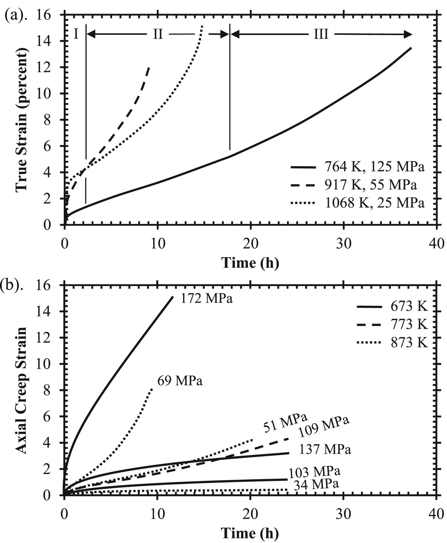
The majority of Decker et al.’s measured stress exponents ranged from 7.6 to 10 with an outlier of 4.7 at 1068 K under low stress conditions which could indicate evidence of dislocation climb controlled creep in that region [94]. Ellis et al. calculated similar stress exponents ranging from 6.6–8.26 for the eight fabrication methods tested [40]. The general range of stress exponents for both studies are indicative of creep behaviour of dispersion strengthened alloys or metal matrix composites. Decker et al. found that GRCop-84’s diverse creep characteristics of pure metal strain and high creep exponents made applying a model of creep behaviour difficult [94]. They attempted to apply a power law relationship, but almost all of the data was well above power-law breakdown and instead applied a hyperbolic sine relationship, which incorporates an exponential dependence on stress, to interpret data.
Both studies applied a Monkman-Grant relationship to compare fabrication conditions. The Monkman-Grant relationship is simple to test; if the slope is constant for minimum creep rate as a function of rupture time, fabrication does not impact the creep properties. Decker et al. found a slope of −1.08 and determined the fracture mechanism was the same between rolled and extruded material [94]. Ellis et al. calculated a slope of −1.11 in agreement to Decker et al.’s results; however, the forward stepwise regression analysis showed a statistically significant impact of processing on creep response, though differences in texture, testing environment, or scatter of the data could also contribute to explaining the results [40]. In 2011, Ellis and Loewenthal [95] conducted a follow-up study to assess the variation of previous creep results. By improving the specimen temperature measurement and control, the scatter in the data was from 2 to ½ orders of magnitude for extruded GRCop-84, demonstrating that the scatter in data collected before the 2011 study is largely due to complications of the testing environment [95]. In particular, different fabrication methods produce roughly the same grain size, but changes to texture can have a substantial impact on creep properties [40]. For the small extrusions, plate, and pre-production sheet there was evidence of texture having an impact on creep, though the change is minimal [40]. Therefore, fabrication method should not be fully excluded from future creep studies of GRCop alloys and could be utilised to improve creep properties by texture control.
Power function constants for high-heat-flux Cu alloys (a) step loaded secondary steady state creep and (b) constant load, secondary, steady state tensile creep; with calculated stress based on the power function constants of the form
converted to
, where n is the stress exponent, A is the pre-exponential factor constant,
is creep rate in units of s−1, and σ is stress; reused from [1] with added calculated stress and some as-received data removed for clarity.
* Indicates that the stress has
Compared to GRCop-84, GRCop-42 has limited available creep data. Ellis and Michal’s study compares the creep behaviour of GRCop-84, GRCop-42, and NARloy-Z [26]. Though, these results are best used for qualititative comparisons. Specifically, both GRCop alloys’ data were not consistent between tests, with over 2% strain difference between tests conducted at the same stress level in some cases and did not fit well to linear trends [26]. In general, GRCop-42’s creep properties were slightly inferior but comparable to those of GRCop-84 [26]. Ellis and Michal noted that the as-extruded GRCop-84 showed limited stage III creep, as shown in the creep curves in Figure 13(b) from a 2017 study by Lerch et al. [96], whereas GRCop-42 was more likely to exhibit more stage III creep [26]. A more recent comparison of extruded GRCop-84 and −42 from Gradl et al. in 2019 [82] shows that the creep rate and lifetimes are similar, shown in Figure 14. While there are some deviations, both alloys still demonstrate similar creep rates and lifetimes under the tested conditions [82]. Gradl et al. postulate that while the Cr2Nb precipitates of the GRCop alloys prevent or reduce grain boundary sliding, grain growth, and grain boundary diffusion, the similarities in macroscopic creep properties are likely caused by the Cu matrix dominating the creep properties [82]. (a) Creep rates and (b) creep lives of wrought GRCop-84 and GRCop-42 alloys; the GRCop-84 data is from warm rolled plate, rather than as-extruded, for higher consistency, and the GRCop-42 data is assumed to be as-extruded; redrawn with permission from [1].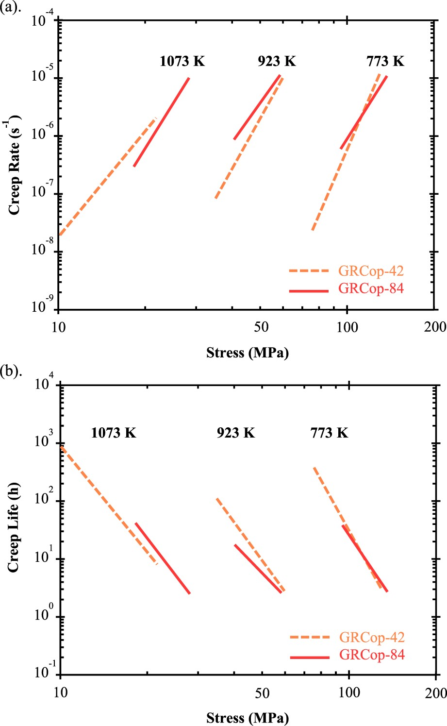
At this time there is little data available on the creep of AM GRCop with the exception of the work conducted by Gradl et al. [88] in 2017, which compared creep rates of L-PBF, wrought, plate, brazed plate, and sheet GRCop-84. Limited data is presented but a thorough discussion of the observed trends is provided instead. Compared to the other fabrication methods, the creep results of the L-PBF samples were more consistent, more repeatable, and better fit a linear trend [88]. Gradl et al. state that ‘ … the properties of L-PBF GRCop-84 are equal to or exceed the properties of conventionally processed GRCop-84 with the exception of the LCF lives’ [88]. Under the same level of stress, the creep rate of L-PBF GRCop-84 is roughly two orders of magnitude lower than that of wrought alloys. For example, the minimum creep rate at 40 MPa and 923 K is 3 × 10⁻⁹ s−1 for the L-PBF alloy and 3 × 10⁻⁷ s−1 for sheet GRCop-84 (when interpreted from its trend line) [88]. The L-PBF GRCop-84’s creep exponent was comparable to the other fabrication methods which agrees with the previous Monkman-Grant relationships, and its dominant mechanism should be the same, although the exact value was not presented for a comparison [88]. Finally, while the creep rate is lower, the improved consistency is considered a major benefit to predicting the performance of the AM alloy [88]. The basic understanding of the origins of L-PBF GRCop-84’s higher creep rate is a subject for future studies and can be potentially related to the characteristics of AM microstructure and defect structure such as (1) strong build texture and its relationships to build/creep directions, (2) AM defects such as gas porosity and lack-of-fusion defects, (3) grain morphology and grain boundary properties, and (4) the characteristics of precipitates.
Thermal expansion
Thermal expansion is a primary factor when evaluating LCTF performance for high-heat-flux applications, especially in the case of the combustion chamber liner where the primary failure mode is driven by LCTF. Ellis stated that thermal expansion in the combustion chamber liner contributes the majority of the stress and strain rather than mechanical sources [2]. The thermal expansions of NARloy-Z, AMZIRC, GlidCop Al-15, GRCop-84, and GRCop-42 are compared in Figure 15 and Table 8 as a function of temperature. These alloys have similar thermal expansion characteristics which makes visual comparison and interpretation of the data difficult, so these are also presented as quadratic equation forms of thermal expansion as a function of temperature in Table 8. Of these alloys, both GRCop alloys’ thermal expansion is consistently lower at temperatures exceeding 700 K which should aid in lowering thermal strain and producing longer LCTF lives. The GRCop alloys’ thermal expansions are comparable up to 900 K, though GRCop-84’s thermal expansion is slightly lower above 900 K which should be the result of its higher loading content.
oBased on recommended values of average literature from [1]. *Estimated from graph of thermal expansion [2], assume ±5% accuracy. **Converted from quadratic equation where T (°C) and has ±1% reported accuracy [3]. +In the extruded condition with 95% confidence; converted from power law to quadratic equation [4]. ++In the extruded condition; estimated from graph assume ±5% accuracy [5].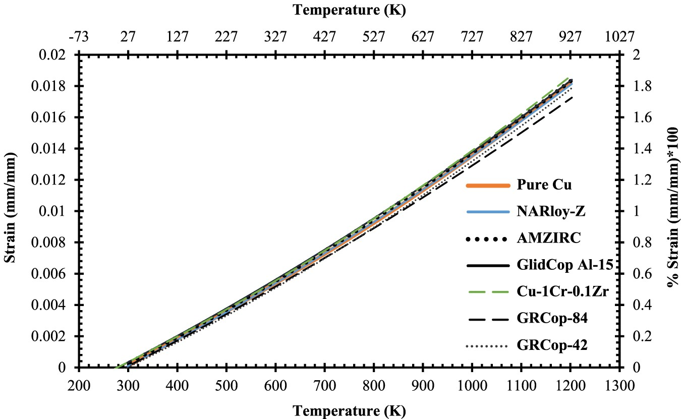
Quadratic thermal expansion equations of high heat flux alloys where thermal expansion, α (mm/mm), is a function of temperature, T, in units of K from α(T)=A(T)2+B(T)+C; these values are accurate only above room temperature and should be considered estimates.
Low-cycle fatigue behaviour
Similar to creep, there are currently only a few available studies on LCF of GRCop alloys and effectively none for LCTF. Mechanical fatigue is not the same as thermal fatigue, but mechanical fatique is more readily tested by LCF and the trends of LCF and LCTF are typically similar. Ellis and Michal’s 1996 publication provides LCF results for only GRCop-84. This LCF experiment was strain controlled with a triangular waveform at a constant strain rate of 0.12 min−1 [26]. Unlike its creep data, GRCop-84’s LCF results were more reproducible and consistent [26]. This is one of few publications to present LCF hysteresis loops, and two representative hysteresis loops from this study are shown in Figure 16. The loops’ shapes and slopes were noted to remain relatively constant and marginally increase in stress during cycling indicating minimal work hardening under the tested conditions [26]. Compared to NARloy-Z, Ellis and Michal found that GRCop-84’s LCF performance was either as-good or better depending on the degree of strain [26]. The relatively high volume fraction of hard Cr2Nb particles are believed to be the cause of this increase, by either preventing or minimising the development of persistent slip bands, NARloy-Z’s particles are too low in volume fraction to have a similar effect [2,26]. LCF stress-strain hysteresis loops (a) GRCop-84 tested at room temperature and 2% total strain; (b) GRCop-84 tested at 811 K and 0.7% total strain; data collected using strain-controlled fatigue tests with a triangular waveform at a constant strain rate of 0.12/min; redrawn with permission from [1].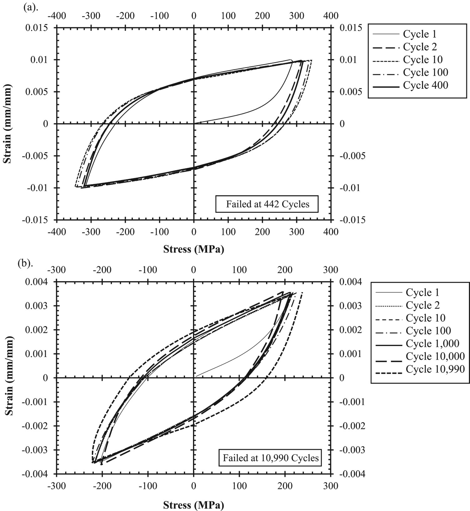
Gradl et al. also presented LCF results on wrought GRCop-84 and GRCop-42 at room temperature, 673, and 873 K with a fully reversed triangular waveform under strain control [82]. The GRCop alloys were tested according to the total strain range with plastic strain and shown in Figure 17 [82]. Gradl et al. observed limited statistical difference or temperature dependence between the GRCop-42’s strain data, so it was combined into a single trendline [82]. Gradl et al. observed that both alloys did not fail below 0.7% total strain and have nearly equivalent performance from a practical engineering perspective [82]. GRCop-84’s strain data was similarly temperature independent with the exception of the 873 K data. The plastic strain, Figure 17(b), shows significant scatter for both GRCop-42 and GRCop-84 data points. LCF trends of extruded GRCop-42 (reported as wrought) with data points and GRCop-84 from [1,2] (a) LCF strain ranges; (b) LCF plastic strains; (c) LCF stress range; RT – 673 K and RT – 873 K indicate that data has been combined from these temperatures to produce these trend lines (as there was no discernible difference in trend between them); redrawn with permission.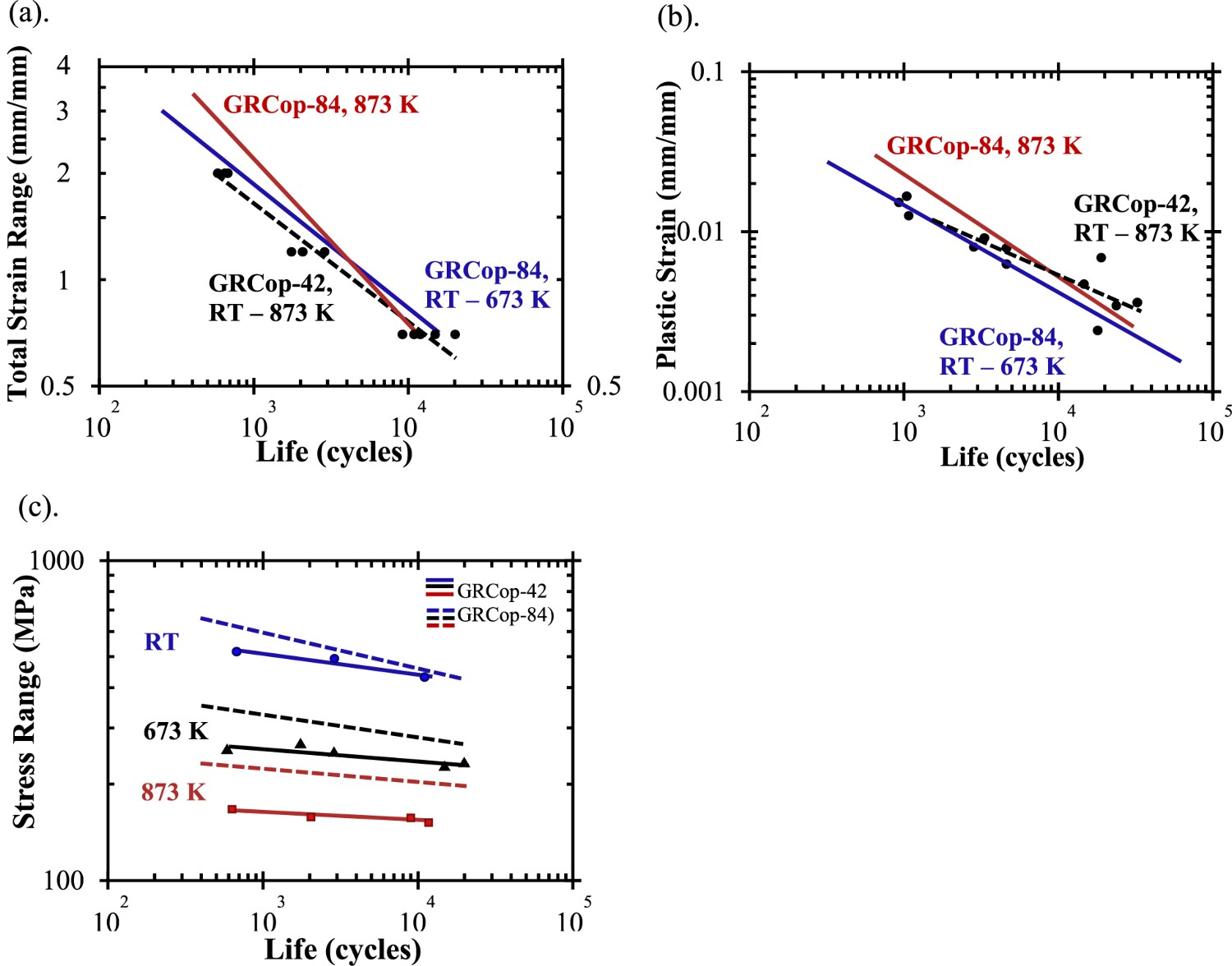
While the strain results were similar between the alloys, the stress range, Figure 17(c), shows the difference between the loading fractions. GRCop-84’s stress is consistently higher than GRCop-42’s, and the difference between them increases with temperature. As Gradl et al. indicate, this means that GRCop-42 has a lower load bearing capacity, consistent with the GRCop-84’s higher strength [82]. These tests are not a full representation of the combustion chamber liner because mimicking the liner environment in standardised test equipment is not feasible. The liner’s LCF is primarily LCTF where thermal expansion should play a significant role, though, as Figure 14 shows, the GRCop-84 and −42’s thermal expansions are largely similar up to 873 K. Compared to GRCop alloy’s UTS, YS, thermal conductivity, and creep response, GlidCop appears to be a better choice for high-heat-flux applications like the combustion chamber liner. However, fatigue is a major failure mode in combustion chamber liners, and GlidCop Al-15’s fatigue behaviour has been described as poor, particularly at high temperatures, compared to GRCop-84 by several sources [2,77,78,83]. Similar to creep, LCF results are difficult to compare due to the variety of factors, and a comparison of GRCop alloys and GlidCop in the same source could not be located. Takahashi et al. [97] performed LCF tests on GlidCop Al-15 similar to the experiment presented by Gradl et al. [82]. At a total strain range of 1% under vacuum and at 473, 543, and 673 K, GlidCop Al-15 failed at approximately 6000, 3000, and 1500 cycles, respectively [97]. Based on the Figure 17 at the same strain, GRCop-84 fails at approximately 6000 cycles between room temperature and 673 K and 5500 cycles at 873 K compared to GRCop-42 which fails at 4500 cycles between room temperature and 873 K [82]. GRCop alloys demonstrate significantly longer lives than GlidCop Al-15 which is in agreement with previous assessments.
Environmental resistance
Outside of creep and LCTF, the combustion chamber liner’s remaining concerns, stemming from the harsh environment, are resistance to H embrittlement and oxidation. High volumes of liquid and high pressure gaseous hydrogen in the combustion chamber liner is a major concern. The Nb content of GRCop alloys is known to be the most susceptible component to embrittlement by forming a solid solution and hydrides with hydrogen [98–100]. Ellis et al. [100] performed thermodynamic calculations with GRCop-84 based on activity and partial pressures. The primary conclusion from this study was that the chemistry of the Cr2Nb precipitates would control, by reducing, hydrogen embrittlement. By adding an excess of Cr, the activity of Nb is reduced along with the risk of hydrogen embrittlement [98,100]. Ellis and Hastings performed tensile, notched tensile, stress, rupture, and LCF tests on extruded GRCop-84 in high pressure environments including high pressure H2, high pressure He, and samples charged in high pressure H2 for 8 h at 922 K [99]. They were unable to find evidence of the formation of hydrides by either optical or electron microscopy, changes in fracture morphology, or statistically significant difference in the mechanical tests [99]. The susceptiblility may change slightly between GRCop alloys and fabrication methods and should be tested, but ultimately, the H embrittlement is largely dependent on the Nb content that is available. The slight excess of Cr appears to be sufficient to consume the majority of the Nb in forming the intermettalic Cr2Nb leaving GRCop-84 with good stability in hydrogen environments.
Rocket combustion chamber liners made with NARloy-Z were susceptible to blanching during operation, so extruded GRCop-84’s oxidation behaviour was investigated by Thomas-Ogbuji and Humphrey and compared to NARloy-Z and OFHC Cu with thermogravimetric analysis (TGA), scanning electron microscopy, electron dispersive spectroscopy, and X-ray diffraction [51,101]. They found that the alloys had similar oxidation rates at or above 1023 K, but at intermediate temperatures closer to the operating temperatures between 773 and 1023 K, GRCop-84 exhibited significantly higher oxidation resistance [101]. In a later study, Thomas-Ogbuji and Humphrey determined that GRCop-84’s enhanced resistance is time dependent and longer exposures result in a greater difference compared to the other alloys [51]. These results are likely tied to the formation of stable Cr or Nb oxides on the surface which require lower temperatures and longer times to form an outer barrier. Thomas-Ogbuji and Humphrey determined likely oxide candidates from X-ray diffraction data collected on oxide scale removed from their samples [101], but changes in the powder chemistry and fabrication methods are likely to have changed this list of candidates and should be reassessed. The reduced Cr and Nb content of GRCop-42 may reduce the formation and efficacy of the oxide layer.
Summary and future prospects
Several microstructural trends are apparent when comparing the state-of-the-art high-heat-flux Cu alloys and Cu metallurgy presented in this review that help understand the essential qualities for optimising high-heat-flux performance. Thermal conductivity is critical and should be preserved by reducing impurities in the FCC Cu matrix. Higher thermal conductivity results in lower operating temperatures which helps prevent thermo-mechanical instability. Conventional alloying limits the fraction of alloying content to preserve thermal conductivity, so their strengthening instead relies on reducing the size of microstructural features. Below 773, GRCop alloys’ have lower thermal conductivity and mechanical strength compared to other alloys but has a highly stable microstructure due largely to the high alloying content of Cr2Nb which is resistant to coarsening and prevents recrystallisation of the microstructure. In high-heat-flux applications with operating temperatures above 773 K and significant LCF concerns, GRCop alloys are among the best available. Cu-rich Cu–Cr–Nb alloys, like GRCop, have potential for use in the next generation of aerospace rockets and structural high-heat-flux applications where reusability and long-term use are desired. Small capability improvements achieved by replacing an existing material can translate to large economic savings and enhanced safety margins and design freedom. In high-heat-flux applications, GRCop-84 and GRCop-42 have similar properties and performance, however GRCop-84 exhibits slightly higher mechanical strength while GRCop-42 exhibits slightly higher thermal conductivity. More statistically relevant data, microstructure information, and cost metrics will help determine which should be chosen for any given application though both have merits.
GRCop alloys have potential in future space-oriented or high-heat-flux applications, e.g. resistance welding electrodes and holders, permanent metal casting moulds, vacuum plasma spray nozzles, and fusion reactor first walls. Fusion reactor first walls carry an additional irradiation concern with the Nb content of GRCop alloys because Nb can cause H embrittlement by absorption of tritium or deuterium [102]. As long as the Cr excess is sufficient in suppressing the formation of Nb by consuming it in forming Cr2Nb, this should not be an issue, but the long term effects and low level waste requirements need to be fully exhausted before practical use. As candidate combustion chamber liner alloys, AM GRCop has shown unique potential for liner fabrication when compared to conventionally wrought material. After HIPing, fully-dense AM GRCop-84 liners have been produced faster and with properties equal to or better than their wrought counterparts. AM of GRCop alloys combined with the intricate geometries of combustion chamber liners represents a rare case where AM provides optimal processing. The greatest advantage AM provides is the ability to manufacture built-in cooling channels. New cooling channel designs with thinner walls and more customisable paths, impossible by traditional machining constraints, will improve the cooling efficiency and design constraints of liners. One development is the cooling channels can be wrapped around the liner and split from one channel at the bottom to three at the top rather than being machined straight down the walls [88]. However, both cooling channel design developments introduce new wall thinning and stress concentrating concerns. L-PBF’s surface finish is relatively poor as it is limited by multiple factors including the quality, size, and sintering of the powder which can serve as crack initiation regions in fatigue, particularly LCF [103]. The exterior of parts can be polished to alleviate these concerns, but internal channels are not easily inspected or smoothed. These concerns must be addressed in qualification testing, and the improved cooling efficiency provided may lower the temperature sufficiently to reduce fatigue. The composition of GRCop alloys is also likely to be optimised or adjusted in the future for either cost or performance reasons. Ellis et al. [104] have shown that relatively low 0.1–0.5 wt-% additions of Zr in extruded GRCop-84 (to GRCop-84Z) can improve the mechanical properties through the formation of Cu5Zr precipitates [8,104]. These Cu5Zr precipitates are smaller than the Cr2Nb precipitates and add 2 vol.-% more to the existing 14 vol.-% of Cr2Nb precipitates in GRCop-84 and are estimated to improve the strength by 23–39% [8,104]. The thermal conductivity is expected to decrease from new potential scattering centres, but conductivity results have not been published [8,104]. It is unknown how additions of Zr would interact in L-PBF and future testing and characterisation is necessary. The additions of Zr demonstrated improved creep performance and elongation compared to extruded material, and HIPed L-PBF GRCop-84 has demonstrated similar improvements, so it is unknown if Zr will significantly benefit L-PBF GRCop.
It is the opinion of the authors that there are potentially three main obstacles to the development of GRCop alloys for future and current scientists and researchers. The first is that the current literature of GRCop alloys is somewhat limited; past experiments should be reproduced and expanded with updated GRCop alloys, and AM GRCop needs considerably more research. Second, the literature lacks a thorough, empirical assessment of microstructure-property relationships for AM GRCop alloys. Comparisons of wrought and AM material may help to better understand the microstructure-property relationships. A prime example is understanding why the creep results of AM GRCop have less scatter than wrought. The last obstacle is a need for more interest in GRCop alloys by industry and researchers outside of NASA. Expansion of the literature and understanding of the alloy will likely bring in new researchers who may elucidate the principles supporting these observations and add to the literature.
Footnotes
Acknowledgements
The authors would like to acknowledge the Manufacturing and Materials Joining Innovation Center (Ma2JIC), made possible through awards NSF IIP-1540000 (Phase I) and NSF IIP-1822186 (Phase II) from the National Science Foundation Industry University Cooperative Research Center program (IUCRC). RPM also acknowledges the financial support of the Center for Materials Processing at the University of Tennessee, Knoxville and Oak Ridge National Laboratory’s Graduate Opportunities (GO!) Program. Special thanks to David Ellis of NASA GRC and Paul Gradl of NASA MSFC for their discussions and comments on this review and historical information.
Disclosure statement
No potential conflict of interest was reported by the author(s).