
Abstract
In this paper, degradation mechanisms of optical materials, used in the light emitting diode (LED)-based products, are reviewed. The LED lighting is one of the fastest technology shifts in human history. Lighting accounts for almost 20% of the global electrical energy use, inferring that replacement of traditional lighting sources with LEDs with higher efficiencies will have major positive implications for the global energy consumption. Organic optical materials are key components in LEDs in the sense that they control the functionality of the device and they have decisive effects on the durability and reliability of LEDs. This paper aims at describing the influences of chemical structure and service conditions on the degradation mechanisms of organic optical materials in LEDs which lead to the lumen depreciation, discolouration, and colour shift of the LED light output. The contributions of different degradation mechanisms of optical and package materials in LED-based products to the lumen depreciation and colour shift are methodically reviewed.
Introduction to light emitting diodes
Solid-state lighting (SSL) technology is one of the greatest technological achievements in the last couple of decades. Light emitting diode (LED), based on SSL technology, is rapidly increasing its share in the general lighting market [1]. The lighting market for LEDs, in particular, is expanding rapidly with a market share that is expected to grow to almost full coverage in 2020. Packaged LED revenue was reported at $14.4B (billion) for 2013 with a projection that the total will reach $25.9B in 2018 (Ref: www.ledmagazine.com). Lighting accounts for ∼20% of the global electrical energy use. LEDs are not only expected to be soon widely used in indoor lighting applications, but they are also becoming increasingly more popular in outdoor and industrial applications. Mobile devices, liquid crystal devices (LCDs), TV screens, and traffic lighting are other attractive market domains for LEDs [1,2]. LEDs have many advantages, compared to more traditional light sources (fluorescent lamps and tubes), including higher light output, smaller size, longer lifetime, eco-friendly, and more colour controllability. Last but not least are the energy considerations in light generation. LEDs have the lowest energy consumption per lumen produced among all available lighting sources [3,4]. The energy issue is obviously an extremely important aspect; knowing that this energy consumption has a major impact on global warming [3]. Figure 1 shows the trend in the energy consumption for the lighting purposes in case LEDs are used as well as the growth in the market share for LEDs. Trend in the energy consumption in the lighting market, in case LEDs are used as well as the growth in the market share of LEDs in different sectors (after US DOE, August 2014).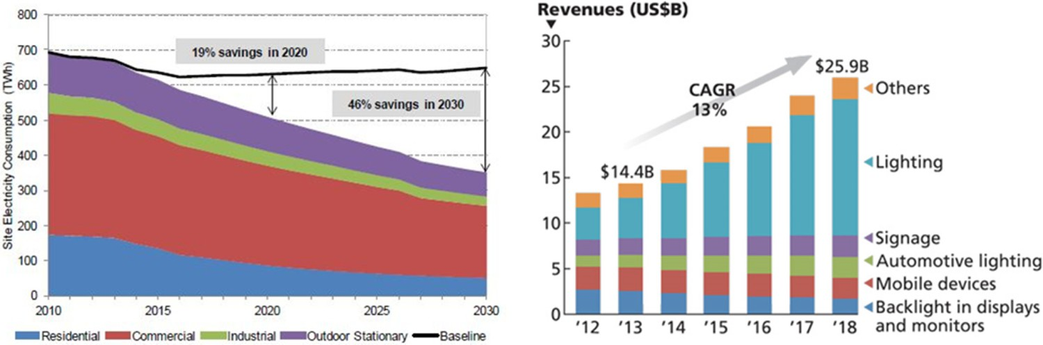
White light output in LEDs can be generated using four different methods [5–14], but the most widely used approach is based on the application of a blue-light chip together with yellow phosphor. In this case, a portion of the blue light radiation excites the phosphor which emits yellow light. White light is then generated by mixing of emitted yellow light (coming from yellow phosphor) with non-absorbed blue light. This method has the highest efficiency of all current approaches if a phosphor absorbs a blue photon at 450 nm and emits a red photon at 650 nm the energy efficiency of the process is 69%, with 31% of the initial energy being converted to heat in the phosphor layer [5]. The combination of yellow phosphor with the blue-light chip can be achieved either by direct deposition of a phosphor layer on or around the chip surface (i.e. proximate phosphor) or by incorporating phosphor particles in the lens (i.e. remote phosphor), as shown in Figure 2.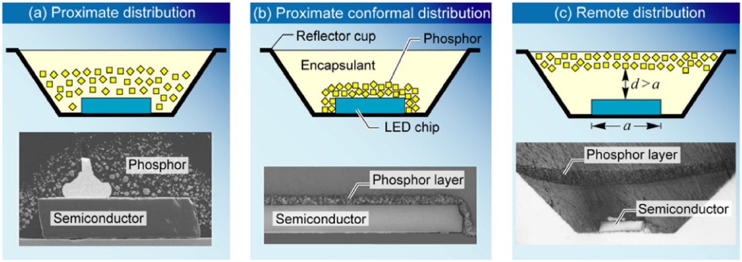
Efficacy, CRI and lifetime of some common light sources [15].
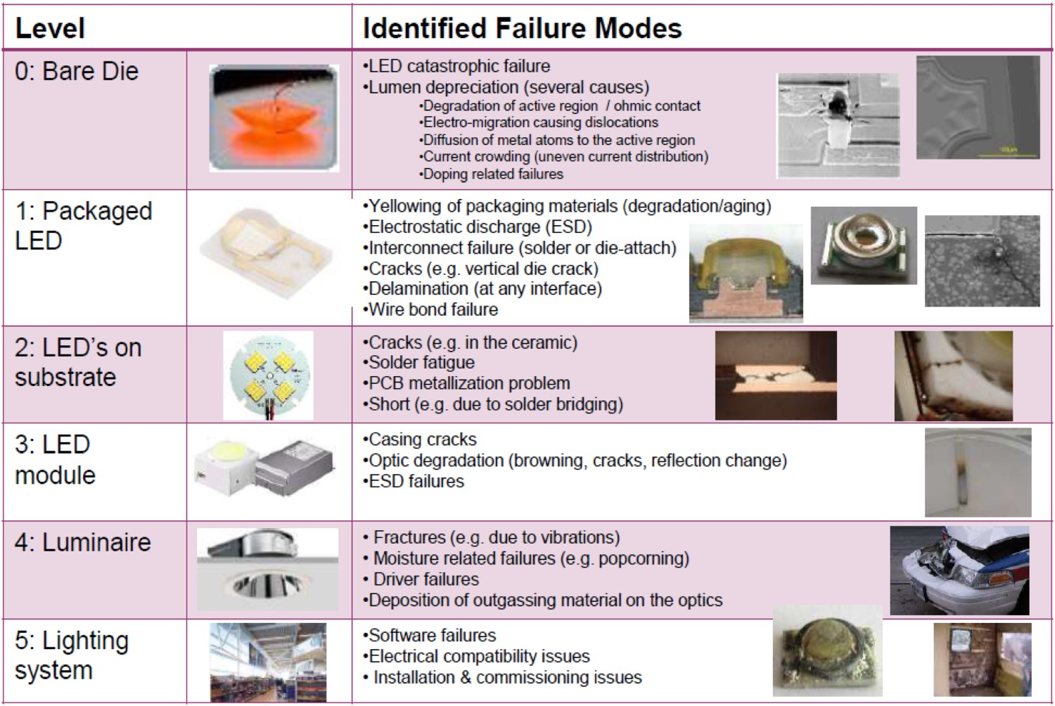
An LED lighting system consists of several components at different levels, making it a relatively complex system. These components have optical, electrical, or thermal functionalities, depending on the roles they have in the system. An LED lighting system has five levels [15,16]. Level 0 is the LED chip or bare die, which is the light-generating diode. Level 1 of the LED lighting system is the packaged LED chip. This system level has several functionalities including protecting the chip, soldered electrical connections to the next level on the bottom of the LED package, colour adjustment with phosphor, and heat management are all functionalities occurring in this level. Level 2 is defined as the LED array packages on a printed circuit board (PCB) to form an LED array or a module. Level 3 is assigned to light modules that are ready for final application, with the LEDs, packaged in a module with simple electrical/optical/thermal components. Level 4 is assigned to the LED luminaire or lamp and combined the light modules with all other system components, including hoursings, sensors, controls, and data processing/communication units. Level 5 is assigned to a collection of luminaires to form a lighting system in space. All explained system levels in SSL system are shown in Figure 3. Over 30 failure modes have been reported in SSL devices and these failures can occur in any system level [17], some being shown in Figure 4. Other report >50 failure modes [add ref to chapter 1 of part II book]. These failure modes are unique to LED-based lighting products and are not comparable with the failure modes of other lighting devices. Fluorescent lamps, for instance, have less than 10 recognised failure modes, with some being inherently as simple as breakage of the glass envelope. Different system levels in an LED system. Identified failure modes in LEDs.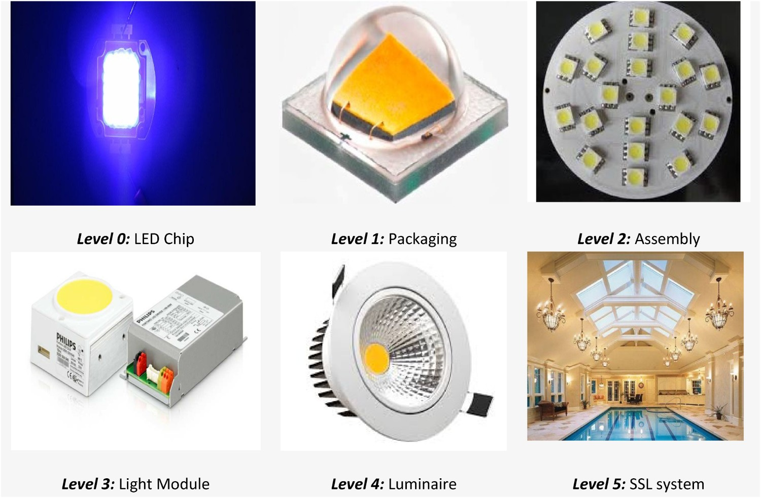
Most commonly seen failures and most dramatic ones are limited to the LED chip, the LED package, and its solder interconnects [17,18]. Some LED failures are not fully known, and more studies are needed to have a deeper insight into them, whereas others have been fully analysed [17]. Some examples of the latter case are degradation of Ohmic contacts [17], failures in the lead frames [18–20], discolouration of encapsulant materials [21], carbonisation of silicone encapsulant [22,23], and thermal quenching of phosphor [24].
Microelectronic components must be protected against the aggressive system and environmental stresses. This is routinely done by covering chips and other microelectronic components with a package that usually includes polymeric encapsulants to prevent the LED chip from being in direct contact with said environmental stresses. So, it is not surprising that many of LED failures are related to the package in a way or another. With that said, obviously, the right choice for packaging material is of crucial importance. The material used in LED applications should be stable enough to withstand the heat and high photon fluxes that occur in LEDs.
The main aim of this paper is reviewing the degradation and ageing mechanisms of different optical materials in SSL systems. This paper can be of great importance when it comes to materials selection for different working conditions. As well, this paper can be used for those who are involved in research, related to optimisation and increasing the lifetime of LEDs. In this paper, currently used optical polymers [25–31] are first introduced. Then common optical degradation mechanisms, observed in the LED polymer lens and encapsulants, are reviewed. Defects and failures are discussed from both chemical and optical points of view. More attention is paid to the ones which could result in significant lumen losses and alterations in the chromaticity of LEDs.
Optical materials, used in LEDs
Explaining and understanding different failure mechanisms in LEDs is not possible without having a fundamental knowledge about the structure of optical materials used in LED packages and other parts of the lighting device. Figure 5 shows the polymeric components of a typical LED system. Polymeric materials used in LED devices need to have an optimum combination of thermal, optical, electrical, and mechanical properties. For LED lighting to be a reliable light source, many technical complexities and challenges need to be addressed. Many of these challenges are introduced and will be discussed in this paper. Some challenges are materials-related, meaning that they cannot be resolved without materials optimisation. Optical materials are expected to have a high refractive index, good chemical resistance, strong adhesion and bond strength, good mechanical strength, stable microstructure, and high resistance against UV radiation. Table 2 gives a few examples of common technical challenges in LEDs, which can be resolved by materials optimisation. Polymeric materials used in secondary optical parts in LEDs [14].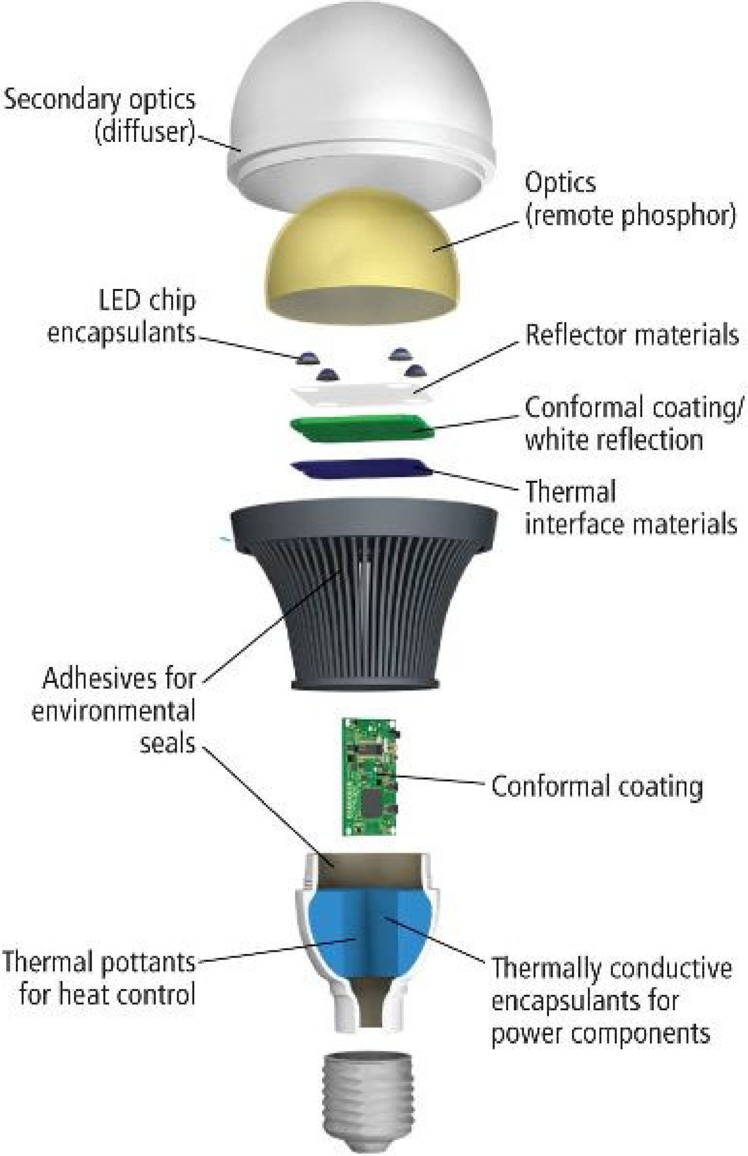
Examples of technical challenges in LEDs, and their corresponding materials solutions.
Among different optical materials in LEDs, those which are more widely used in LEDs will be introduced in this paper, as follows.
Silicone
Silicones, having superior optical, thermal properties, are a serious competitor to other more traditionally used polymers (more specifically polycarbonates). The most widely applied silicones are polydimethylsiloxanes, polydiphenylsiloxanes, trimethylsilyloxy, methyl-phenyl, and terminated silicone. The latter has a unique structure in the sense that it is a semi-organic substance in which organic groups (vinyl, methyl, etc.) are combined with Si–O inorganic backbone. The chemical structure of a general silicone is shown in Figure 6. Chemical structure of a general silicone.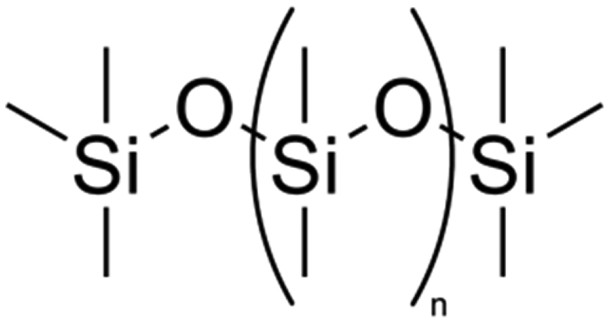
Silicones typically show absorption bands at 770, 1000–1100, and 1260 cm−1 in the infrared spectra. They do have some unique characteristics, including excellent moisture/UV light resistance, superior biocompatibility, and structural stability during service [32–40]. What makes silicones an attractive choice for LED applications is the fact that they maintain their electrical properties at high temperatures and in humid environments [34]. However, silicones are known to have some disadvantages, including their relatively low tear strength, poor adhesion, low glass transition temperature, large coefficient of thermal expansion (CTE), high moisture and gas permeability, and their relatively long production times. Another disadvantage of silicones is their price, which is higher compared to engineering polymers such as bisphenol-A polycarbonate (BPA-PC).
Recently, silica has been added to silicone to improve the mechanical and thermal stabilities of LED encapsulants. This obviously results in more chain stability, and this lessens the chain scission as a pathway to the degradation of silicones [36]. Comparing phenyl silicone with methyl silicone, one can see that the former has almost 10% more light output due to its higher refractive index. This will have a huge positive impact on the performance, reliability, and the final cost of the product provided that the thermal stresses remain low [37]. There are a couple of studies which deal with the effects of environmental factors on the structural evolution of silicones [37]. At this point, it is important to mention that a comprehensive way of looking at the degradation of silicones would be to match the chemistry and production method of silicones with environmental factors they face during use. Neglecting any of the mentioned aspects would certainly result in premature of the material and any device they are protecting. Details will be discussed later in this paper (see Section ‘Degradation of Silicone’).
Bisphenol-A Polycarbonate
One of the most commonly used polymers in LED device packaging is bisphenol-A polycarbonate (BPA-PC), which is a thermoplastic, with the formulation shown in Figure 7.
BPA-PC is known to have a relatively high elastic modulus, high fracture resistance, and very good thermal stability which leads to its widespread use for secondary optics in LED devices. Its applications are not limited to the LED market domain. In fact, BPA-PC is widely used in many other industrial sectors including compact discs (CDs), DVDs, safety and sunglasses, automotive interior, riot shields, and drinking water bottles [41–50]. There is a great deal of information about the structure, properties, and thermal/optical degradation mechanisms of polycarbonates [51–65].
Polymethyl methacrylate
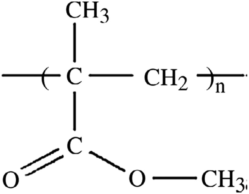
Another extensively used thermoplastic in LED lens and packaging is polymethyl methacrylate (PMMA) [66–72], with its structure being shown in Figure 8. PMMA is one of the cheapest options in the market. The widespread use of PMMA has to do in part with the glass transition temperature of PMMA, Tg, being between 105 and 110°C, which makes its processing and manufacturing relatively easy. PMMA is also commonly used for decorative and biomedical purposes including automotive windshields, window glazings, and displays. Biomedical uses of PMMA leverage the excellent biocompatibility of this polymer [73]. PMMA is known to have an excellent light/UV transmittance [74–79]. The downsides of PMMA are its tendency to discolour under high water absorption, low heat resistance, and low abrasion resistance [80–94]. Chemical structure of bisphenol A polycarbonate (BPA-PC). Chemical structure of PMMA.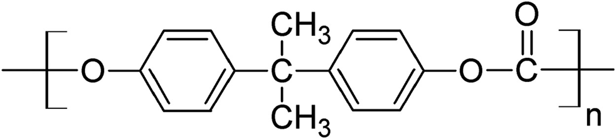
There are many reports about the atmospheric, thermal, and UV light-induced degradations of PMMA [95–117]. The most commonly used analytical methods to study the degradation mechanisms and products in case of PMMA are UV-Vis, FTIR, and mass spectroscopy [118–137].
Epoxy
At this moment, epoxy materials have the biggest share in the LED packaging market [15] due to a good combination of low price, ease of manufacturing, mechanical stabilities, and moisture resistance [138–145]. Epoxies are widely used as die-attach and underfill adhesives and are used in many printed circuit boards (PCBs). The epoxide functional group which is the basis of the epoxy is, in fact, a strained oxygen-carbon ring, as depicted in Figure 9. The easiest way of making epoxies is the reaction of BPA with epichlorohydrin which results in (2,2-bis [4-(2′3′epoxy propoxy) phenyl] propane), also known as diglycidyl ether of BPA (DGEBA) [32,33]. As well, it is a routine practice to produce epoxies from the reaction between alcohols and glycols with epichlorohydrin or phenol-formaldehyde resin with epichlorohydrin [32]. The end product of the former reaction is aliphatic epoxy and that of the latter one is Novolac epoxy. Novolac epoxy resin, cured by anhydride or amine agents, in general exhibits excellent chemical and thermal properties, which expectedly has to do with rather high aromatic and cross-link densities in this resin. Chemical structure of Epoxy.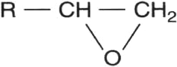
Epoxy resins are known to have two major shortcomings as LED encapsulants. The first issue is the brittleness of this resin due to the excessive cross-linking. The other disadvantage is the photodegradation of epoxy under radiation at high temperatures. Massive chain scission takes place at the said condition, resulting in a fast discolouration. Discolouration cannot be tolerated in LEDs since it leads to a reduction in transparency and a drop in light output [143].
Phosphors
Phosphors are typically combined with the polymers mentioned above and combined into parts of the LED lighting system such as enapsulants and lenses. Phosphor plays a vital role in a group of white-light LEDs by converting blue photons produced by the LED into white light through the process of photoluminescence (PL). These LEDs are commonly termed phosphor-converted white light LEDs (pc-WLEDs) [146–160]. Blue/UV light radiation from LEDs can be absorbed by the phosphor, resulting in an electron gaining sufficient energy to transition from the ground state energy level to an excited state energy level. These energised electrons will then lower their energies by emitting a photon through the process of luminescence [159]. This radiation can be in the form of visible light, UV, or infrared, depending on the difference between the energies of the excited and ground electronic states. Since phosphor excitation in LEDs takes place by absorption of a photon in the blue or UV spectral regions, the process is named PL [154].
Examples of commonly used phosphors in pc-WLEDs.
Degradation of optical materials
Chromaticity shift in the output light is one of the most common failures in LEDs [161–181]. It is considered as one of the most important measures of quality and is often studied and reported [182–204]. Colour shift defined as the change in the chromaticity coordinates from its original values. It is named chromaticity shift, in case CIE1976 (u′,v′) chromaticity diagram is used. The (u′,v′) coordinates are related to the CIE 1931 (x, y) coordinates. A practical way of measuring the chromaticity shift in LED light sources is using MacAdam ellipses steps [28–31].
As a case in point, Scott Rosenfeld [19] reported chromaticity-consistency and chromaticity maintenance problems in LED lamps in a museum, using chromaticity shift, as shown in Figure 10. Chromaticity shifts as large as Δu′v′ = 0.0024 were observed after only 4000 h of operation. Colour shift results from the Smithsonian Institution [19], reproduced with permission.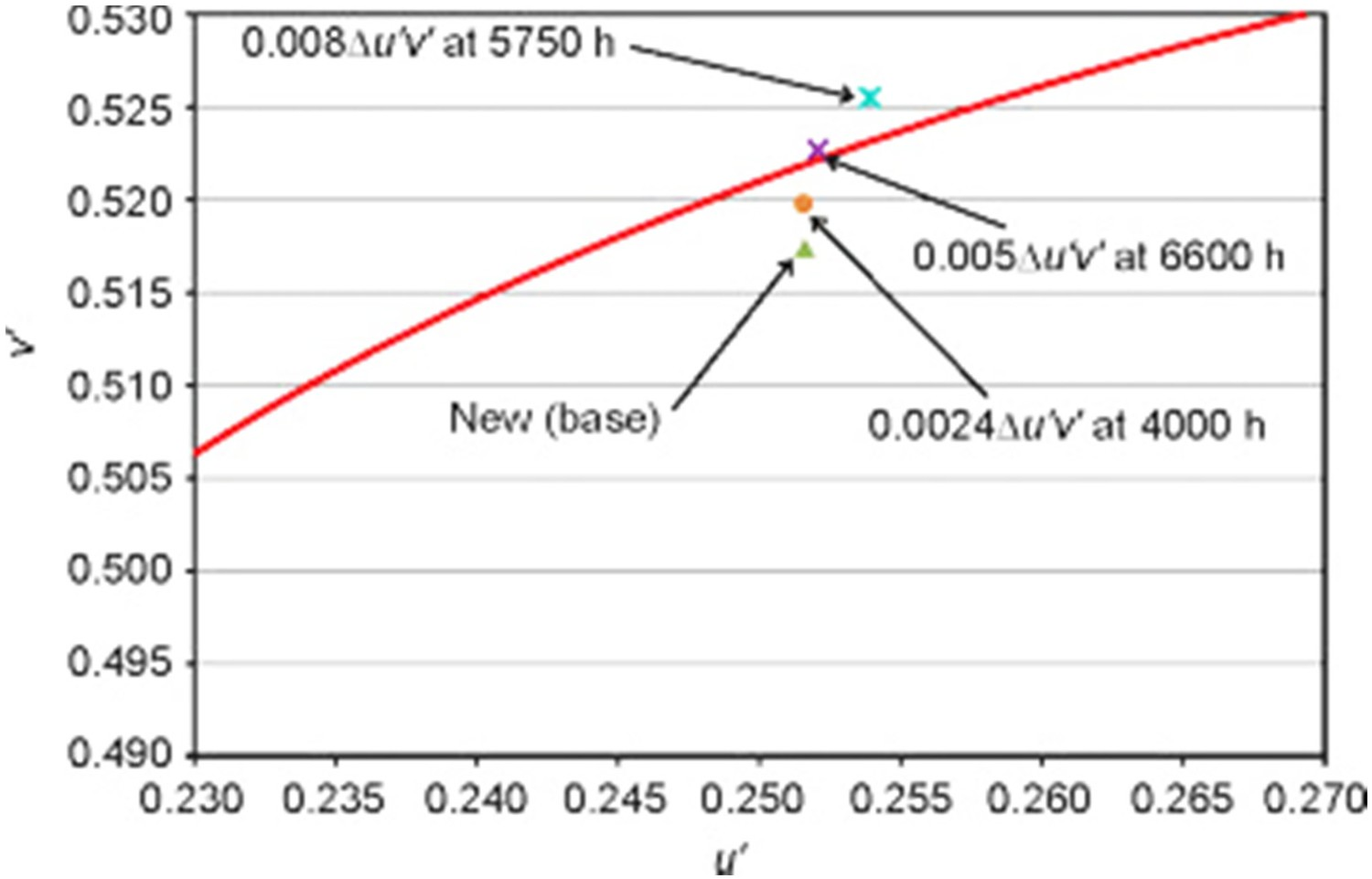
In another example, the dependency of Δu′v′ on temperature is shown for the Philips Lumileds Luxeon Rebel LED package in Figure 11 [199]. Results show that there is initially a rather fast shift in the chromaticity at all given temperatures, followed by a period in which the shift is almost negligible. The third stage is accompanied by a decrease in Δu′v′. The higher the temperature, the shorter is the plateau (second stage), such that the plateau is hardly discernible at 105°C. Even during the region of minimal change in Δu′v′, there can be significant changes in Δu′ or Δv′ [195]. Effects of temperature on the chromaticity shift (Δu′v′) of Luxeon LEDs operated at 1 amp [199], reproduced with permission.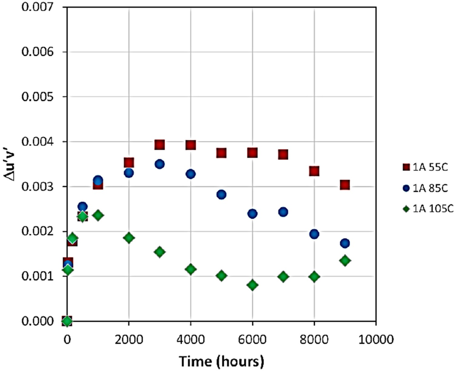
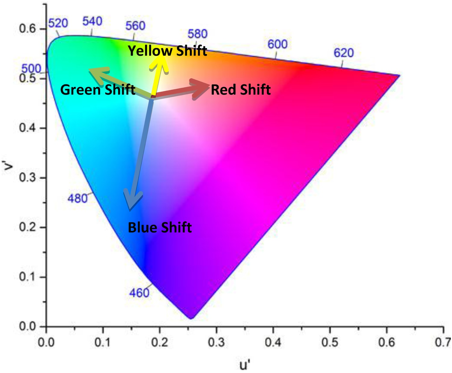
Degradation of optical components in LED packages can have one of the most significant contributions to the chromaticity shift of LED devices. This has to do with the fact that optical components in LED packages have a central role in the optical performance of LED devices by controlling the emission of light from the device. In fact, any depreciation in lumen output may involve a chromaticity shift as well [161–176]. As already mentioned, an LED lamp is a complicated system, containing secondary lenses, reflective layers, and diffusers, all intended to achieve a desired light emission pattern. Interrelations between mentioned components can have some implications for the chromaticity maintenance of the device during its lifetime. There are many different reasons that can lead to chromaticity shifts in LED luminaires and lamps. Given that chromaticity shifts can be originated from optical materials and/or subsystems (e.g. lens or diffusers), the directions of chromaticity shift can be different from case to case, as shown in Figures 12 and 13. Directions of chromaticity shifts [201]. Illustration of colour shifts in the CIE 1976 colour space. Any change in the spectral proportion of any colours results in a chromaticity shift.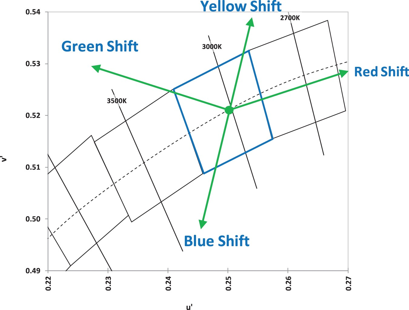
When chromaticity maintenance is a concern, LEDs exhibit much better performance, compared to halogen and CFL lamps [164]. Figure 14 shows the change in the chromaticity of three mentioned light sources with time. Average change in the chromaticity of different light sources with time [205].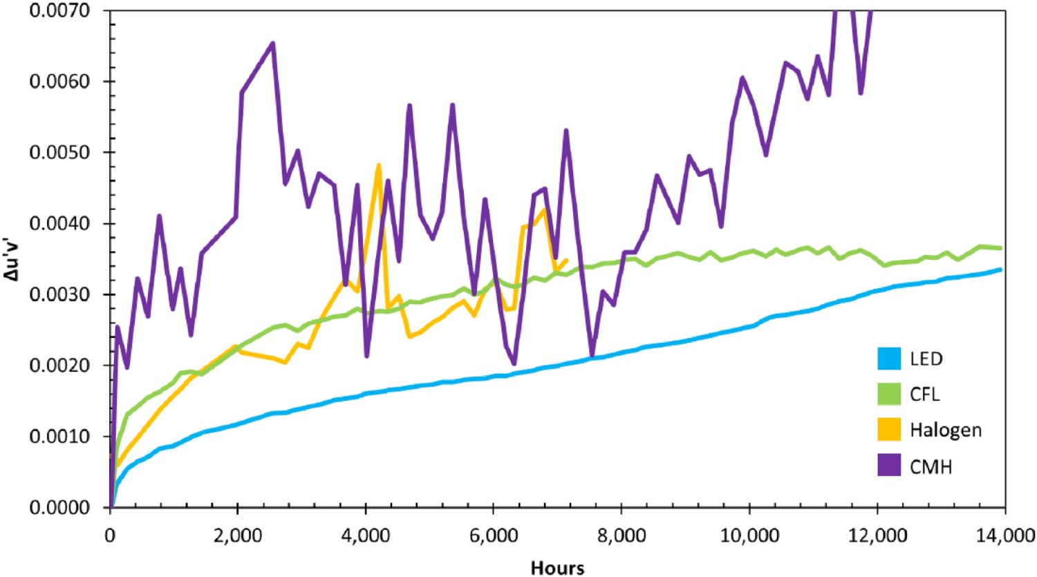
LEDs, depending on their package type and manufacturing method, will have different chromaticity shift regimes [197,206]. The direction of the chromaticity shift is to some extent an indication of the degradation mechanisms that are active. For instance, any shift along the blue-yellow line is due to a change in the relative proportion of yellow to blue emissions. A shift in the blue direction could possibly be related to a combination of the loss of phosphor quantum efficiency, the operation of the phosphor beyond its saturation flux level, and mechanical damage such as cracks in the phosphor–binder interface. A green shift is an indication of a change in the wavelength of the emitted light, which in most cases is related to the phosphor. A yellow shift in most cases has to do with either an increase in the efficiency of phosphor, related to either temperature decrease or change in the chemical structure of the phosphor such as photo-brightening. In addition, discolouration of the reflector, oxidation of the secondary lens, and delamination/cracking at the phosphor-binder interface can cause yellow shifts. A red shift can be observed when a direct red light emitter is used [205]. Alternatively, a reduction in the balance of green emissions can also cause a shift in the red direction [203].
Other factors influencing chromaticity maintenance in LEDs include ageing-related structural changes of emitter, phosphor, and package/encapsulant materials. Ageing is accompanied with a decrease in the radiant flux of emitter over the time. Ageing can also influence the quantum efficiency of the phosphor. Encapsulants can undergo ageing-induced yellowing, cracking, and oxidation. In addition, the refraction index of encapsulants can also change in the course of time which can impact light extraction. Temperature accelerates the kinetics of degradation and therefore increases the magnitude of colour shift within a certain period of time. Temperature dependency of the chromaticity shift of a LED system is also a function of the manufacturing processes, LED design, and packaging materials. The chromaticity shift taking place in LED-based products can in some cases be attributed to diffusion and reaction of contaminants, degradation of optical materials, and delamination at the interfaces. Among these reasons, optical materials degradation is the most crucial one. This includes the ageing of reflective surfaces inside the LED package as well as ageing of lens and encapsulants. The presence of contamination in the system can also have implications for the colour shift in LEDs. For instance, contaminants can alter the characteristics of reflective materials inside the LED, for example, by dulling silver, or by carbonisation of silicone. Another important cause of colour shift in the LEDs is believed to be interface delamination, which is defined as splitting of two materials at their interface [205]. In outdoor applications, the exposure of the package to the UV light can become a major concern. Even though the chromaticity shift issue has been comprehensively investigated, there are still many unknowns. More investigations should be conducted on the influences of lens materials, design, and different stresses (thermomechanical, photo-thermal, and hydrothermal) on the colour shift in LEDs.
Summary of main failure mechanisms, which will have contribution to the colour shift [206].
Discolouration
Polymeric materials degrade under light exposure and elevated temperatures, leading to chemical degradation through mechanisms such as chain scission and oxidation. Chemical ageing of polymers leads to the discolouration and yellowing of encapsulant/lens materials producing an increased absorption of blue light. Figure 15 illustrates the effect of photo-thermal ageing on BPA-PC. It is shown that in the wavelength 400–450, the absorption of blue light increases due to the oxidation of the lens materials [54]. Transmission of light in photo thermally aged BPA-PC [54], reproduced with permission from Elsevier.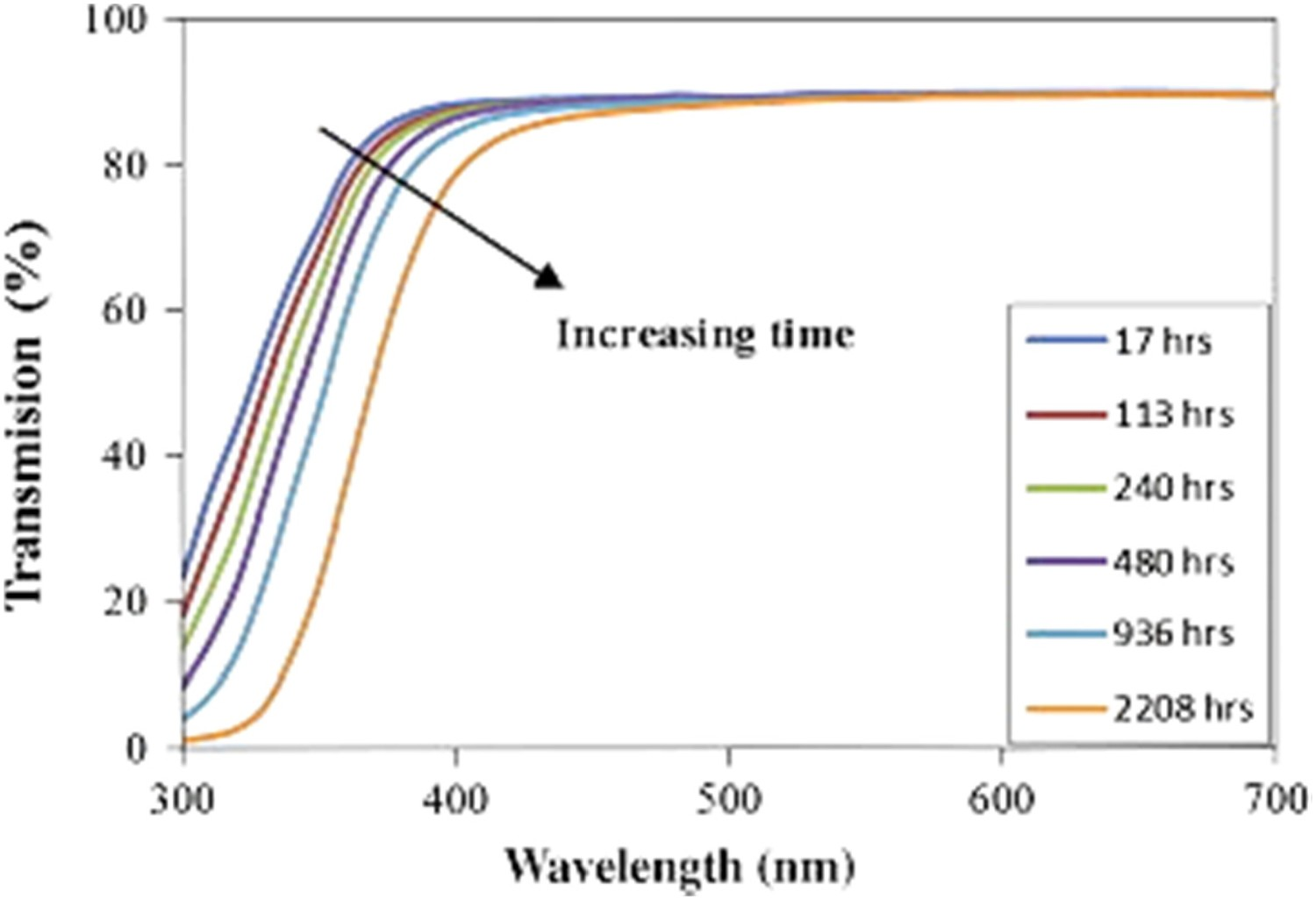
The photodegradation of polymeric materials reduces their transparency, leading to the reduction of light output. The magnitude of this effect is typically dependent on the wavelength, with shorter wavelengths exhibiting larger attenuation [204]. Photodegradation depends on the exposure time and the intensity of radiation. The thermal effects, related to a junction temperature of the LED chip self-heating of the package [10] also play a major role in polymer discolouration in LED-based products [10]. Yazdan Mehr et al. [18] studied the effect of both thermal and photo-oxidation induced discolouration of BPA-PC. They have shown that radiation of blue light accelerates the thermal yellowing of BPA-PC. Narendran et al. [10] also postulated that temperature has a more prominent contribution to the yellowing than the short-wavelength radiation. The effect of humidity on the discolouration of polymers depends on the type of polymer. While epoxy is not significantly affected by high humidity levels, BPA-PC shows more sensitivity to humidity [55].
Lens cracking
Degradation of optical properties in LEDs is not always controlled by chemical reactions. Sometimes it is originated from a mechanical defect in the system that may be caused by the chemical degradation of the polymer. One of the most common cases is the appearance of small cracks in the LED package, which increases internal reflections in LEDs, and this in turn adversely affects the light output of the device. This failure is reported to be more probable in PMMA and glass lenses which are used as a secondary lens. In addition, the operation condition is also considered to be a determining factor. For instance, stress variations induced by thermal shock can accelerate the formation of cracks in the epoxy lens [171,172]. Also, humidity and thermal exposure can result in deterioration of mechanical strength as well as fracture resistance, both having negative implications for crack resistance [173]. Xing Chen et al. [173] examined the effects of a phosphor coating on the structure and mechanical properties of silicone-phosphor composites using a uniaxial tensile test method. Results showed that the elongation of the composite is dependent on the volume fraction of phosphor [173]. It was also shown that crack initiation is more likely to take place in the vicinity of phosphor particles, where strain concentration is expectedly higher [173]. Adding phosphor to the polymer at some point is accompanied by stirring. If it is not performed well, bubbles could possibly be introduced to the mixture. De-aeration can eliminate most of macro-bubbles from the product. However, there is a chance that small bubbles cannot be completely extracted. When the polymer (especially silicone) undergoes curing, these small entrapped bubbles will to some extent expand and move towards the top surface of the encapsulant until polymer curing is complete. Moisture will also cause cracking by leaving an air gap after evaporation. Multiple heating and cooling cycles with the LED in on/off states will cause the defect to grow in size and the relative impact to increase. The importance of entrapped moisture on the lumen depreciation in LEDs and on the formation of cracks in silicone encapsulants, when both temperature and humidity are active stresses, have been reported by several research groups [36,184–186]. Examples of mentioned cracks are shown in Figure 16. Cracks in the silicone after degradation [185], reproduced with permission from Elsevier.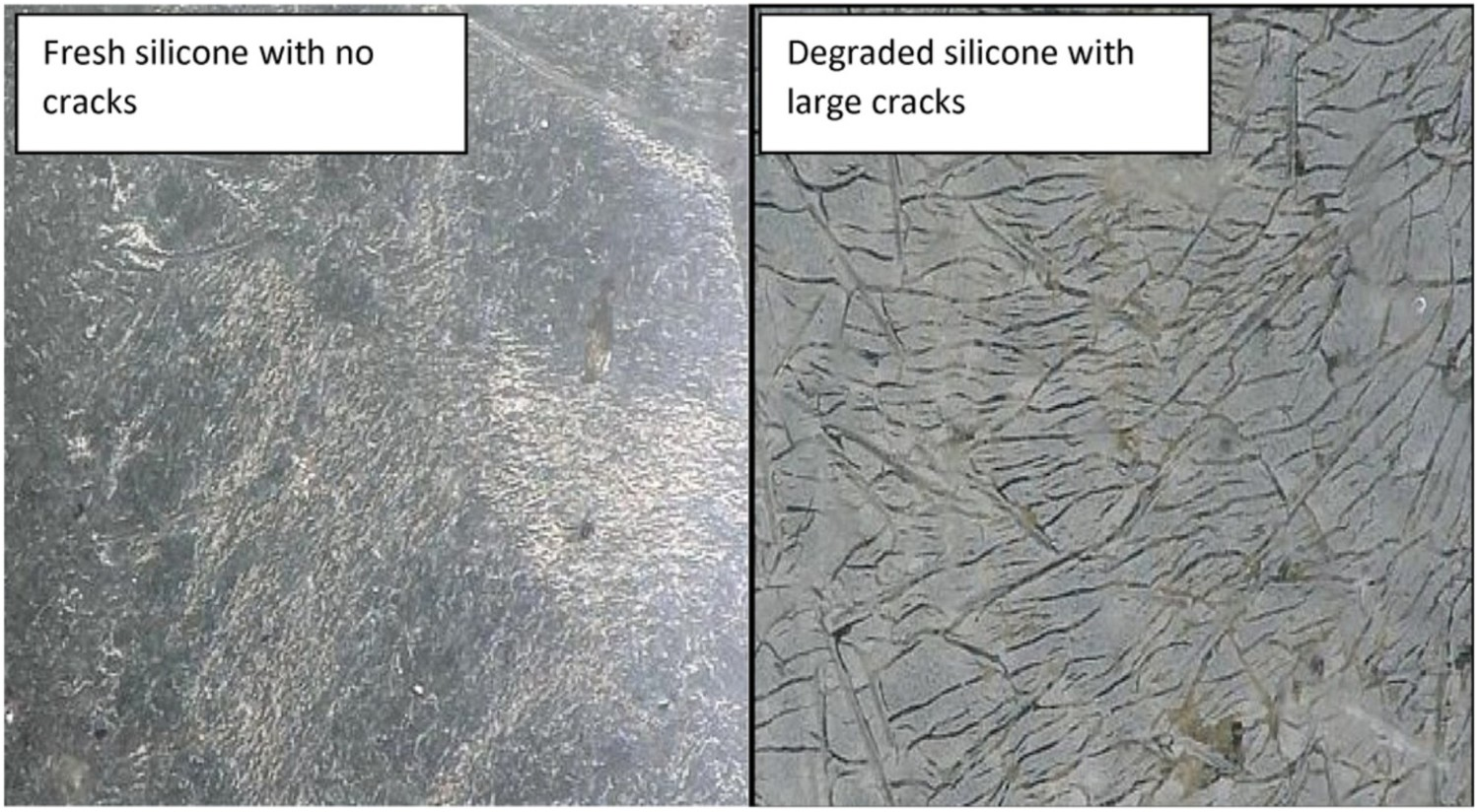
Delamination and debonding
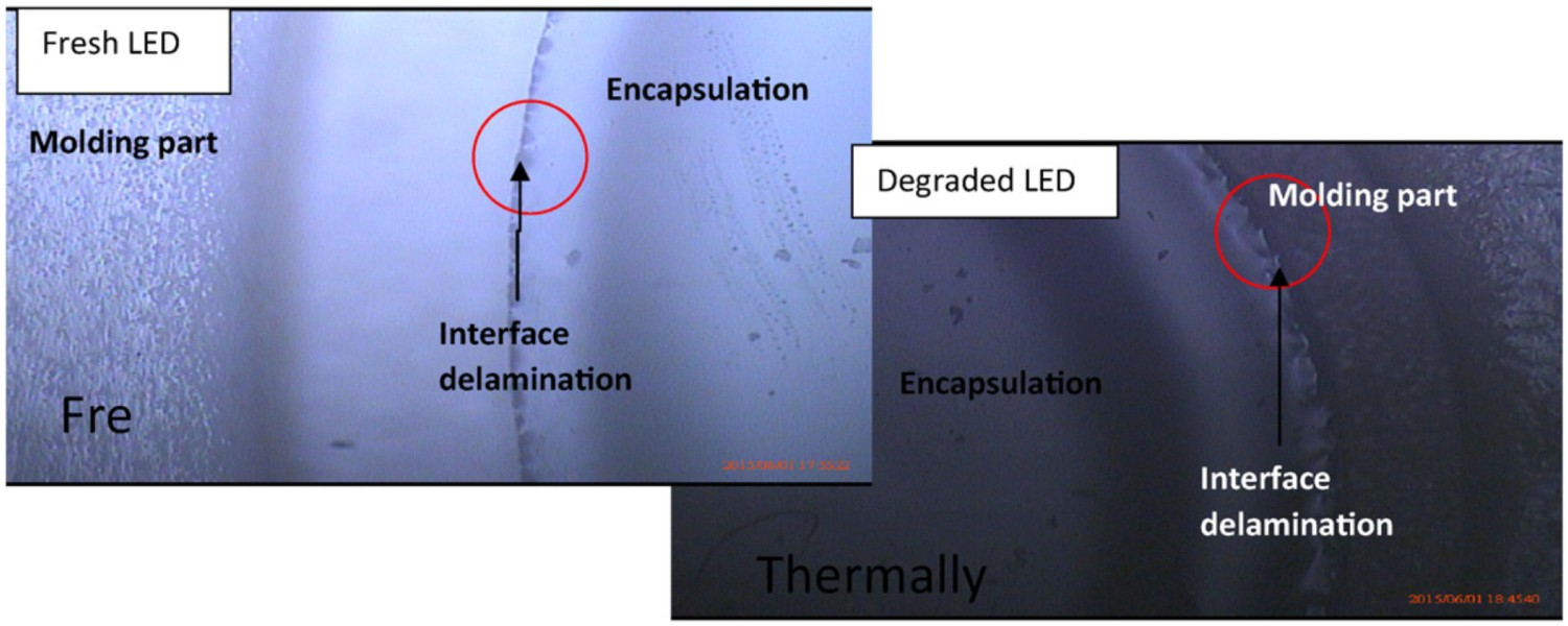
One of the most prevalent failure mechanisms in high-powered LEDs is the delamination at the chip/phosphor interface, which in most cases is accompanied by chromaticity shifts in the yellow direction. Also, debonding at the soldered areas, mainly caused by the existing differences between the CTEs as well as temperature cycles during production and service is another commonly observed failure modes in LEDs. Severe delamination is also reported at the interface of lead frames and epoxy moulding compound (EMC) used to encapsulate the lead frame [65,171,172]. It is reported that curing of epoxy resins during production is associated with a significant shrinkage, which is a source of internal stress and mismatch in the package [164]. In mid-power packages, the device consists of silicone encapsulants, metals, and moulding resins such as epoxies, each having different CTEs and mechanical properties. The integrity of the device in such complicated combinations strongly depends on the thermomechanical cycles during the production process as well as operating conditions. Any minor deviation from optimal production and operation windows can quickly result in delamination at the substrate/optical path interfaces. Figure 17 shows how the peeling of the phosphor-silicone secondary conversion layer at the edge and at the centre can influence the optical properties of the LED. In the former case, more blue light is allowed to escape without having interaction with phosphor, which can cause a chromaticity shift towards blue [171]. When delamination occurs (as shown in Figure 17), a low index of refraction material (i.e. air) is introduced into the optical path and the angle of refraction is changed. This is especially important in the central delamination example where the change in angle of refraction increases the path length of blue photons through the phosphor as shown in Figure 17. This mechanism is accompanied by a chromaticity shift towards the yellow direction. This has to do with the fact that central delamination increases the average path length of blue light in the phosphor, indicating that more blue light can be absorbed by the phosphor layer and be converted into light of longer wavelengths (i.e. yellow). It is shown that moisture not only penetrates into the bulk of lens and encapsulant, but it also penetrates into the interface between these two [188,189]. Figure 18 shows examples of the mentioned interface delamination. Edge and centre phosphor delamination in LED package [164]. Optical microscope images of interface delamination in white high power LEDs [190], reproduced with permission from Elsevier.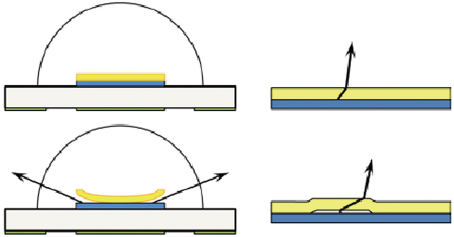
Carbonisation
Carbonisation is also believed to be an important reason for chromaticity shifts in LED packages [176]. It is reported that silicone can undergo severe carbonization, only by applying sufficient electrical current to the LED package to cause dielectric breakdown and an arc [176]. Carbonisation of the polymer material on the chip surface under electrical overstress leads to the damage of the diode by the formation of a conductive path across the LED. Carbonisation of the encapsulant also decreases the insulation resistance, significantly inhibiting its ability to provide electrical insulation between bond wires and lead chips [113]. The failure mode of carbonisation of the encapsulant is light output degradation. Meneghesso et al. [59] reported that polymer carbonisation was present along the bond wire, suggesting power or temperature-related encapsulant degradation.
Microstructural aspects of degradation
Chemical changes and chemical reactions, due to different stresses.
Degradation of silicone
Effect of temperature
Temperature is one of the most important failure accelerators in LED systems. There are many studies, dealing with the influence of temperature on the optical properties, performance, and reliability of LED packages [59–64]. A key issue in this regard is to understand how temperature influences the chemical structure of the polymer over time and how this will affect the kinetics of thermal ageing. That is the reason that the majority of papers in this subject are focused on the chemistry and chemical aspects of degradation reactions [59–61]. On the other hand, there are a few papers, with their emphasis being mostly on the optics rather than the structure and the chemistry [60,62].
The thermal ageing of silicone/YAG phosphor composite specimens at 85°C leads to an initial increase in the conversion efficiency of YAG phosphor at the early stage of degradation, followed by a red shift [40]. The kinetics of temperature-induced degradation of silicone rubber/carbon black composite was also studied by TGA analysis in nitrogen [38]. It is known that adding conductive carbon black to silicone enhances its thermal stability. In that sense, carbon black is even more effective than silica (which is also commonly added to silicone rubber) [63,64]. Results show that the initiation of thermal degradation is at about 350°C and it approximately ends at 600°C [38]. Thermal degradation in silicone is always a multi-stage reaction. As well, the activation energies of degradation reactions are temperature-dependent, with this dependency becoming weaker at elevated temperatures. Effect of thermal ageing on silicon delamination is shown in Figure 19 in which the delamination at the silicone/PPA interface is seen in both blue and white LEDs. Effects of thermal ageing on the interface delamination failure in white and blue LED packages [193], reproduced with permission from Elsevier].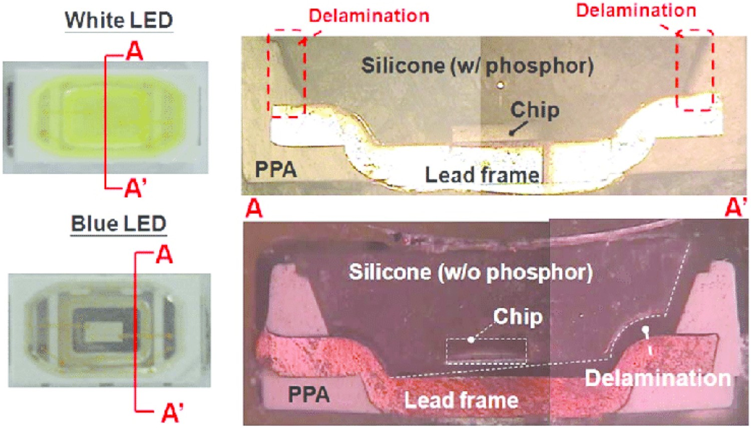
Effect of light
Fischer et al. [40] studied the influences of UV radiation on the mechanical and optical properties of silicones. Both discolouration and embrittlement, related to UV light exposure were observed and reported in their study. Fischer et al. [40] postulated that both mentioned phenomena are linked to UV-induced generation of radicals. This is followed by cross-linking reactions and consequently embrittlement and mechanical failures. With that said, it is not surprising that increasing the cross-link density in silicone and lowering the motion of chains, formed as a consequence of UV irradiation, can contribute positively to the optical and mechanical characteristics of silicone. Photo-induced radical generation in silicone can also result in the creation of nano-sized metallic clusters, which in turn accelerates the kinetics of discolouration in silicone. Figure 20 shows sandwiched samples of different kind of silicone glues after UV exposure. It is shown that the discolouration upon UV irradiation seems to be a general feature, being nearly independent of the molecular structure of the silicones. Picture of the sandwiched samples of the silicone glues after UV-exposure under vacuum using the ESTEC SUV facility [40].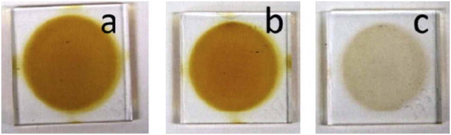
One of the main failures in silicone materials in LED-based products is carbonisation caused by electrical overstress. It is reported that silicone can undergo severe carbonisation, by applying current to the LED package resulting in dielectric breakdown [176]. Also, silicone carbonisation can in some instances be attributed to either of the following reasons (or a combination of them); (i) Over-absorption of blue light by the phosphor, (ii) Joule heating, (iii) Self-heating of phosphors, and (iv) radiation of lights with shorter wavelength (than blue light). An example of carbonisation is shown in Figure 21 in which the device is aged using temperature and current. Carbonisation in LED package, (a) aged at 400 mA and (b) aged at 220°C [198].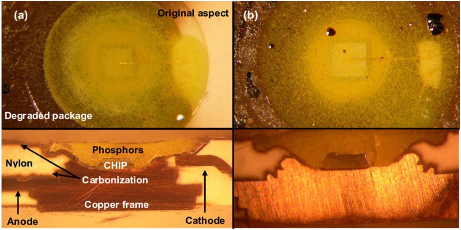
Effect of moisture and contaminations
To understand the attribution of humidity to the optical degradation of silicone, one needs to know the mechanisms of absorption and diffusion of water in silicone. The work, done by Xiao et al. [145], is a good reference in this regard, especially the part which correlates the absorption/desorption of water to the degradation reaction of silicone. Hydrothermal ageing of silicone, in the beginning, is accompanied by water absorption, confirmed by a weight increase. Assuming that water diffusion in silicone follows a Fickian law and that the degradation reaction is essentially controlled by hydrolysis, a model with a perfect agreement with experimental observations was proposed [145]. Zhang et al. [36] performed a series of experiments to examine the influences of humidity on the luminescence properties of the phosphor layer on silicone/YAG phosphor composites [36]. They concluded that a high level of humidity substantially decreases the conversion efficiency of silicone/YAG phosphor composites. Chemicals and contaminations can also result in LED light quality degradation and discolouration of encapsulant materials. Figure 22 illustrates the degradation effect from a volatile organic compound (VOC) that permeated the silicone encapsulant and covered the LED chip [207]. Influence of thermal ageing on the discolouration of LED optical package [207].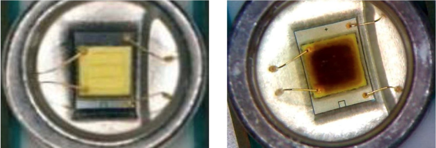
When an LED lamp is in use (especially in the presence of heat and humidity), moisture can diffuse inwards and will go into these entrapped bubbles, which in turn results in an increase in their volume. Expanded bubbles at the interface can deteriorate the bond strength and hence can cause interface de-cohesion. Clusters of small voids can therefore form and at some point, the coalescence of voids are expected to take place. Figure 23 shows an example of the mentioned phenomenon. In this case, significant lumen depreciation is anticipated [183]. (a) Different forms of bubbles in silicone encapsulants and (b) effects of bubbles on the lumen output [183].
By increasing ageing time moisture level inside packaging materials in LED increases continuously. The hydro-mechanical stresses due to thermal mismatches can deteriorate the strength of the interface bonding, leading to the delamination [191,192]. Figure 24 shows typical delamination at the polymer/lead frame interface. Absorbed moisture has obviously an accelerating influence by providing oxygen and hydrogen ions [183]. Delaminations in at the polymer packages of Luxeon [183].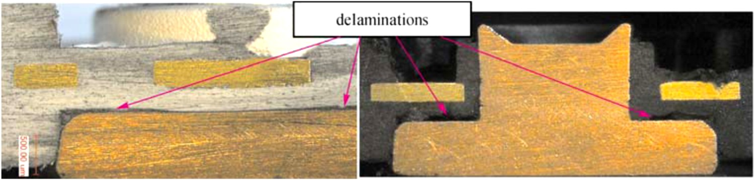
Degradation of polycarbonate
Effect of temperature
Lee et al. [58] systematically studied the thermal degradation of BPA-PC above 300°C. They proposed three temperature-dependent degradation regimes; with the first step being oxidation at 300–320°C. At a slightly higher temperature range (340–480°C), oxidation is followed by depolymerisation. Finally, at the third degradation mode, what controls the kinetics of thermal degradation is the chain scission reaction, reported at the temperature range 480–600°C. In an attempt to get closer to the real LED operational conditions, Yazdan Mehr et al. [60,62] performed a series of thermal degradation tests for BPA-PC polymer at 100, 120, and 140°C. This is addressed in Mehr et al results [21,60,62]. Thermal ageing at a low-temperature regime is associated with oxidation and rearrangement reactions, both having implications for discolouration of LEDs. A major consequence of yellowing is a decrease in the transmissivity in LED lenses [61]. Whether the rearrangement or oxidation reactions controls, the discolouration depends on the temperature and oxygen contents. Davis et al. [56] proposed that rearrangement products are expected to form at high temperatures, in the absence of oxygen. More common rearrangement products in BPA-PCs are phenols, phenylsalicylates, and diphenylcarbonates [52]. At low-temperature conditions, when oxygen is available, the formation of oxidation products in BPA-PCs is more anticipated [58,59]. Rivaton et al. [49] divided the oxidation reactions into two categories; ring and chain oxidation. They performed accelerated thermal ageing at conditions of thermo-oxidation at 170°C. FTIR results (Figure 25) showed that dicarboxylic acids formed in ring oxidation thermally cyclise to form anhydrides characterised by the infrared absorption bands observed at 1860 and 1840 cm−1 of the appearance of infrared absorption bands at 1724 and 1690 cm−1, attributable to aliphatic and aromatic ketones, are the evidence of side-chain oxidation in thermally aged PC. Changes in the carbonyl region of IR spectra of thermo-oxidised PC film at 170°C [49].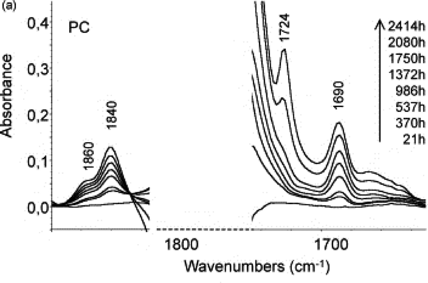
The oxidation reaction in BPA-PCs can easily be confirmed by checking the FTIR-ATR spectra of specimens. Any increase in the absorption intensity around 1690, 1840/1860, and 1713 cm−1, related to cyclic anhydrides, aromatic ketones, and cyclic anhydrides, could be a confirmation of thermal oxidation reaction [49]. In addition to the mentioned tendency for the chromaticity/colour shift in the secondary lens, encapsulant/lens materials in the LED package are also prone to turn yellow. This discolouration, in most cases, is oxidation-driven. Discolouration of BPA-PC lens in different conditions has been comprehensively studied in previous works [60–62]. We showed that both thermal and photo-ageing result in yellowing and colour shift [60].
Effect of light
Light exposure, either in the UV or in the visible range, is considered as an important failure mode for packaging materials. The general concept is that light-matter interactions can increase molecular mobility in the polymer and they can also generate chromophores, with both being known as the main reasons for photodegradation. Photodegradation reactions in BPA-PC, in particular, take place via different reaction pathways known as oxidation and photo-Fries rearrangement. Depending on the wavelength, either of the said mechanisms can become dominant with the former being more important at wavelengths higher than 340 nm and the latter at a wavelength lower than 300 nm [46,47]. However, there are some reports, showing that photo-Fries rearrangement products can also form at wavelengths higher than 300 nm and indicated by the rising absorbance with time shown in Figure 26 [55]. Photo-Fries rearrangement at 340 nm irradiation [63], reproduced with permission from Elsevier.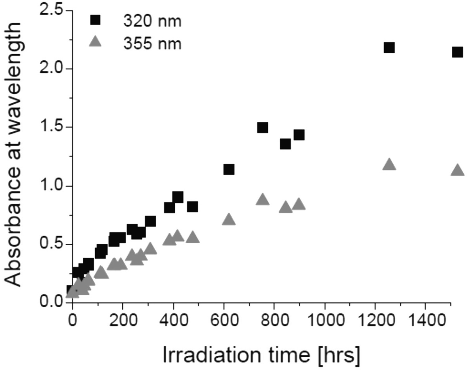
The fact that polycarbonates contain phenyl ester groups makes them prone to undergo photo-Fries rearrangement reactions. This rearrangement reaction takes place in three steps; (1) the creation of radicals, (2) the recombination of radicals, and (3) hydrogen abstraction. More specifically, this reaction is accompanied by the rearrangement of carbonyl groups to phenylsalicylate (L1), dihydroxybenzophenone (L2) and L3, as depicted in Figure 27. The formation of photo-Fries reaction products deteriorates the optical properties of BPA-PC sample by increasing light absorbance. Photo-Fries rearrangement products (a) L1, (b) L2, and (c) L3 [44], reproduced with permission from Elsevier.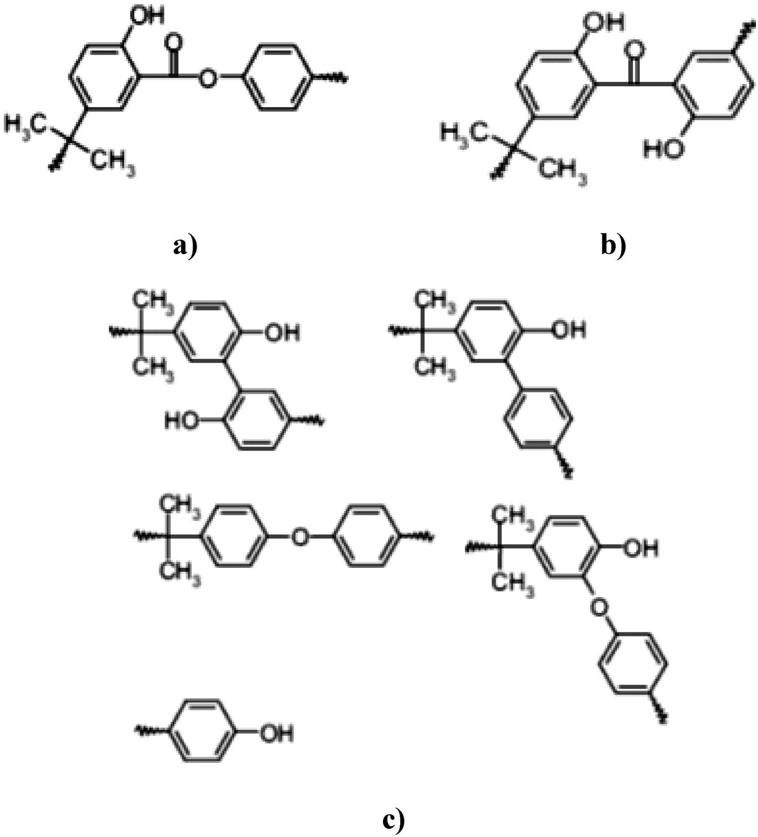
As noted before, when the interacting light has wavelengths of greater than 300 nm, oxidation reactions in BPA-PC are more likely to take place than rearrangement reaction. Oxidation occurs in either the side chain or in the rings, but the probability of side chain oxidation in BPA-PC is reportedly higher than ring oxidation [35–44]. LED systems, based on blue-light emitting chips, are obviously in the long wavelength regime since the blue light has a wavelength in the range 445–450 nm. It is often safe to initially assume that both oxidation and rearrangement can potentially contribute to the degradation. Obviously, depending on the wavelength one might have a more dominant effect than the other. Light–PC interactions gradually change the colour of BPA-PC and decrease its transmissivity. This obviously can have negative impacts on the lumen output and effective lifetime of LEDs. A factor, named yellowing index (YI), is widely used to quantify discolouration in LEDs [62]. In one of our previous works [62], it was shown how YI changes with ageing time. YI alteration with time typically takes place in two successive regimes. The first stage is the induction period, where the YI is almost constant. In this induction period, the magnitude of oxidation and photo-Fries products is not high enough to induce any discolouration. At some point, the rate of the discolouration reaction is accelerated, and BPA-PC samples begin to turn yellow in colour. The transition time between the induction and the acceleration depends on the temperature and environmental conditions such as humidity and light levels. Obviously, the higher the temperature, the earlier the BPA-PC enters into the second regime [54]. Figure 28 shows this typical two-stage behaviour in BPA-PC. In this case, the applied stresses were temperature and temperature plus light. As expected, the induction period in the latter is faster and the YI is higher, inferring that light radiation can have a significant attribution to the yellowing [62]. Effects of temperature and temperature plus blue light radiation on the YI of BPA-PC samples [62], reproduced with permission from Elsevier.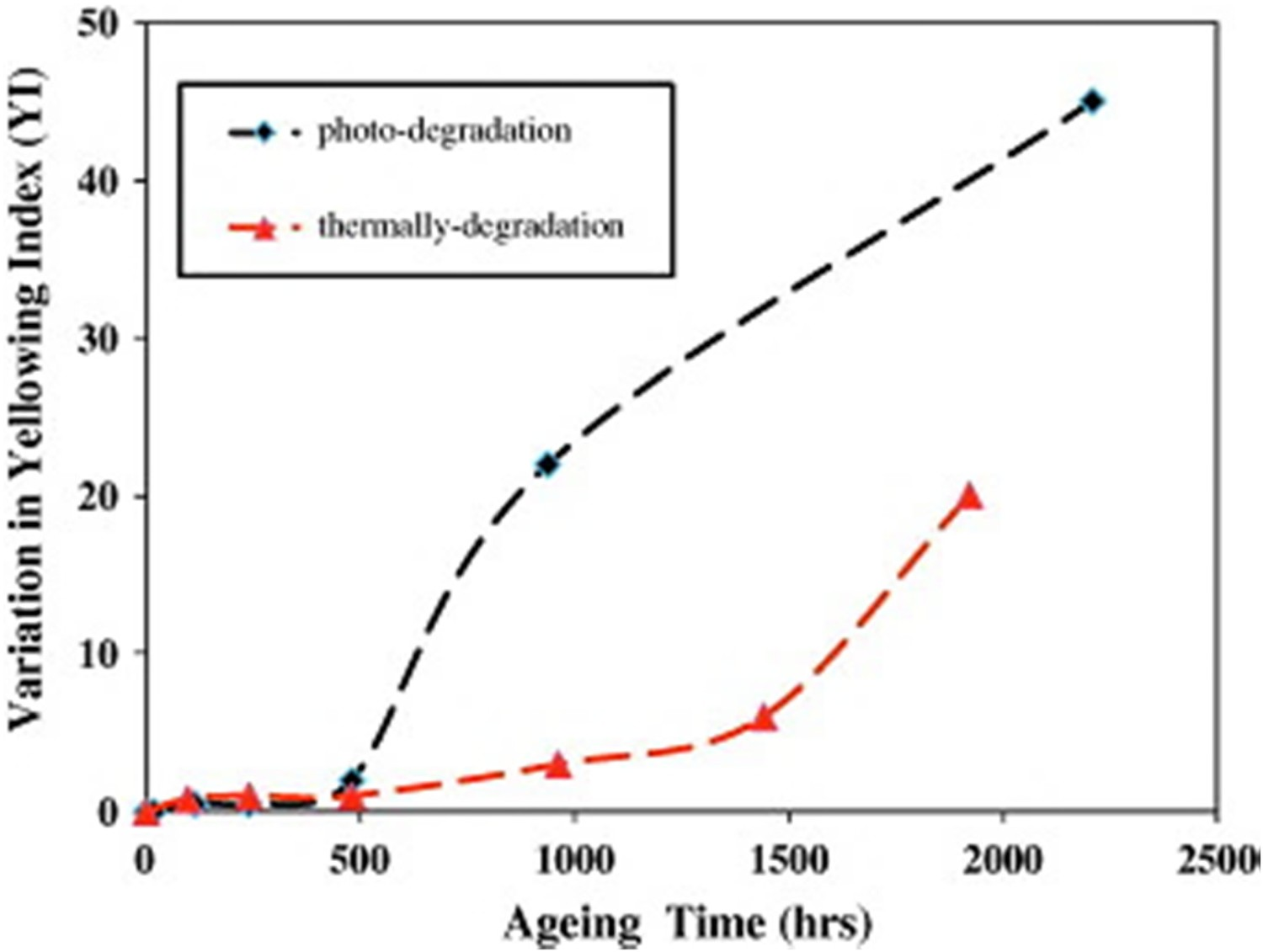
Effect of moisture
Given that in many outdoor applications, polymers are expected to function well in atmospheres of high humidity, understanding the nature and consequences of moisture-polymer reactions becomes crucially important. Clark et al. [54] examined the effects of high levels of humidity (% 50 relative humidity) on the photodegradation reactions of BPA-PC [54]. It was shown that in such high levels of humidity, the photo-oxidation reaction becomes a dominant degradation reaction. More details of their study are shown in Figure 29. The similarity between the nature of the surface after 180 days’ exposure at two locations of Hot/WET and Hot/Dry is evident from the intensities creasing the intensity from C9O and O–C9O, and C–O components. It is clear from these data that extensive photodegradation has occurred. The carboxylate feature is predominant over the carbonyl component after 12 and 24 months’ exposure in H/D conditions, the reverse being the case for H/W weathering. . Cls X-ray photoelectron spectra components assigned from curve fits for photo- aged PC sample in wet/dry condition.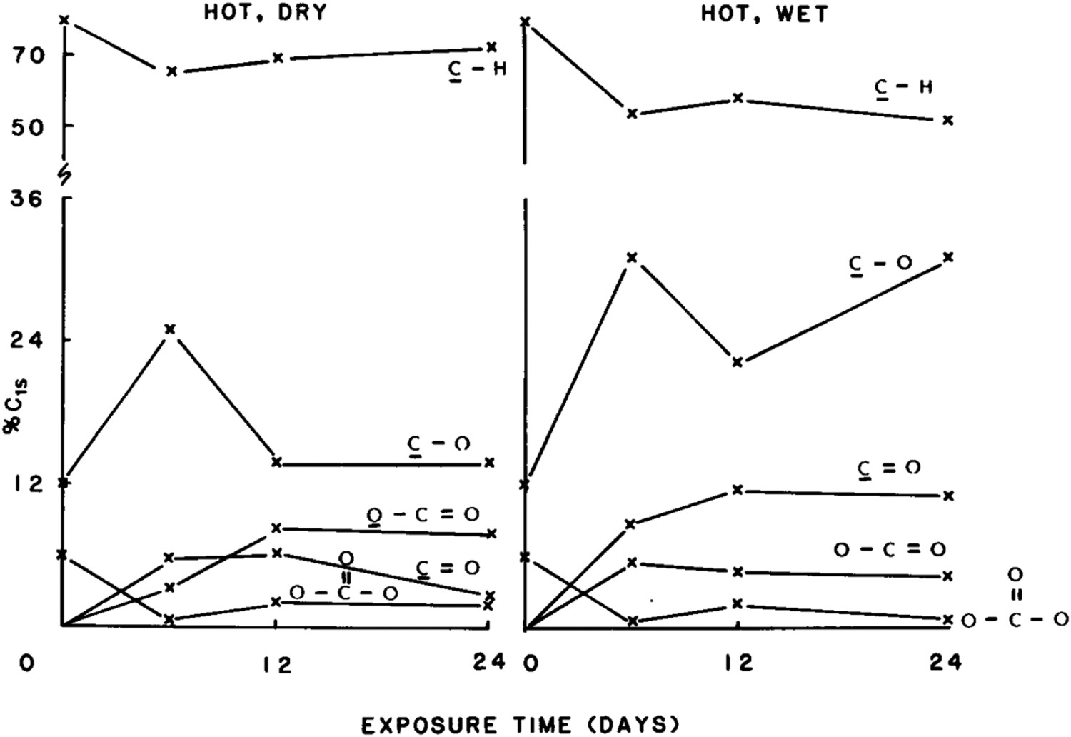
Robert et al. [64] also studied the influence of humidity on mechanical characteristic of BPA-PC. In this investigation, BPA-PC tensile specimens were aged for more than 15 months at relative humidity levels of 0, 75, and 100% and temperatures ranging between 60 and 93°C. They showed a significant weight reduction due to the hydrolysis of their BPA-PC samples. At a certain critical weight, a sharp drop in the strength of BPA-PC was observed. At this transition point, samples no longer showed ductile behaviour, and they all fractured in a brittle mode. Extrapolations, performed at this study [64], showed that it takes 5 years to reach this ductile-to-brittle transition point if BPA-PC sample is kept at 38°C at 100% relative humidity. Yet, even long before this transition, elongation is adversely affected due to the hydrolysis reaction. The influence of humidity levels (up to 42% relative humidity) on the kinetics of photodegradation reaction in BPA-PC, exposed to UV light up to 3000 h, was also studied [65]. Results showed that photo-oxidation reactions became dominant with increasing ageing time. Humidity-induced photo-oxidation, associated with weight loss, results in the yellowing of the polymer and depreciation of its optical properties. The latter includes a decrease in light transparency and increase in haziness. The humidity-assisted photo-induced yellowing reaction is believed to be self-accelerating [65]. Rivaton et al. [208] also investigated the effect of moisture on photo-aged polycarbonate. They showed that products with molecular vibrations at 1840 and 1860 cm−1 have low intensity in aqueous conditions, compared to the dry condition, showing that oxidation products are dissolved by water.
Degradation of PMMA
Effect of temperature
The temperature-induced failure of PMMA has been widely studied [77–88]. Thermal degradation of PMMA is accompanied by the transformation of initial structure to monomers when heated up to 550°C [78–81]. As well, there are some indications [85–88] that at least in some cases, degradation in PMMA takes place by the elimination of the side-groups and formation of unsaturated products. In PMMA, chain scission has a minor influence on the kinetics of thermal degradation due to that fact that the rate of recombination reaction of chain ends in this polymer is rather high [87,88]. Namouchi et al. [79] studied the influence of thermal exposure on the electrical properties of PMMA polymer. PMMA samples in their study were subjected to a continuous heating-cooling thermal cycle, with the maximum and minimum temperatures being 45 and 20°C, respectively. Results showed that oxidation has a prominent attribution to the thermal ageing of PMMAs. Lu et al. [91] drew a similar conclusion concerning the attribution of oxidation to the thermal ageing of PMMA. In their study, PMMA specimens, subjected to thermal exposure at 150°C, showed a significant raise in the FTIR oxidation peaks inferring that oxidation has taken place during thermal exposure [91]. Lue et al. [91] showed that at lower temperatures (around 100°C), absorption peaks in the range of 1500–1600 cm−1 appeared in the FTIR spectra of PMMA samples as a consequence of thermal ageing. This peak is attributed to the asymmetric stretch of the carboxyl ACOOH group, which is an oxidation product. This finding confirms the occurrence of oxidation in PMMA during thermal ageing, even at temperatures as low as 100°C. Figure 30 illustrates that humidity, temperature and blue light radiation on PMMA. Infrared spectra of aged PMMA at different conditions [91], reproduced with permission from Elsevier.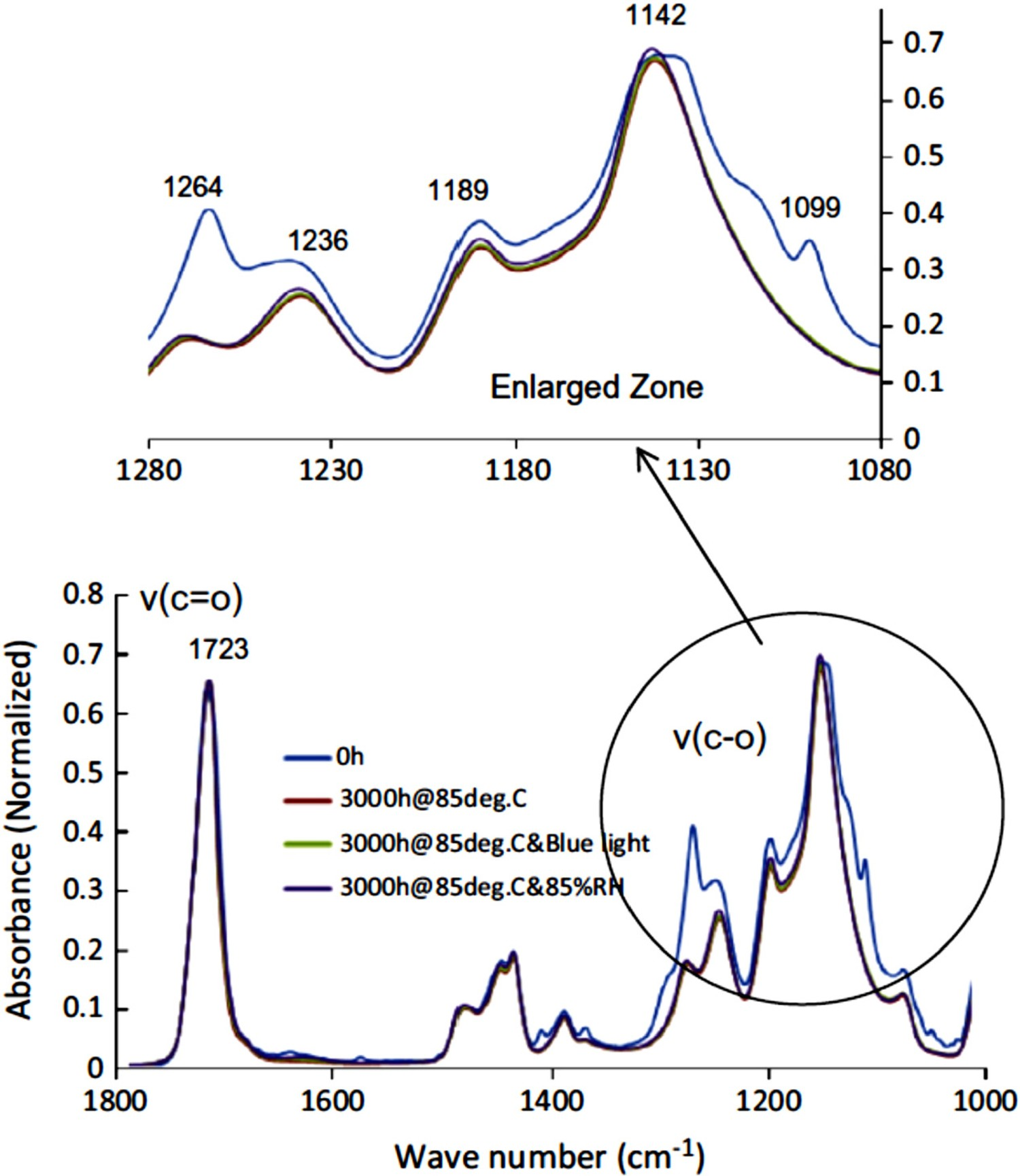
While Lue et al. [91] claimed that such low-temperature oxidation has hardly any influence on the transmission spectra of aged PMMAs, Estupinan et al. [93] reported 1.01% decrease in the transmission at 450 nm, after only 90 h of temperature exposure at 72°C. This contradiction is most probably due to minor differences in the initial structure of PMMAs, used in these two studies. Luo et al. [94] studied the creep behaviour of PMMA at different temperatures under different loading conditions. Crissman [95] also tried to postulate how the chemistry and physics of degradation in PMMA are linked to its creep rupture characteristics. Cheng et al. [98] also studied the influence of thermal degradation on the mechanical properties of PMMA, using a scratching method. In fact, increasing the ageing time lowers this critical load. This link between the crack initiation strength and the degradation extent, if it is well understood, can be used as a simple and effective way of studying the thermal aging of PMMA.
BPA-PC and PMMA are normally used as a secondary lens in LED packages, due to their comparatively lower costs. Royer et al. [164] postulated that in case BPA-PC and PMMA are used as a secondary lens, they hardly have any contribution to the discolouration and colour shift of LED devices [164]. Lu et al. [93] examined the influence of temperature- and blue light radiation-induced degradation of BPA-PC and PMMA on their chromaticity shifts of LED devices. Results, depicted in 31, show that discolouration in both BPA-PC and PMMA lenses results in a change in the spectral power distribution, and this obviously leads to chromaticity and colour shifts. In the case of BPA-PC, degradation at 85°C up to 3000 h is associated with a decrease in the intensity of blue light peak, with almost no change in the intensity of the yellow peak. This obviously results in a yellow shift. Under similar test conditions, PMMA showed comparatively much lower changes (see Figure 31), inferring that in that sense it has a much lower sensitivity to the photo- and thermal degradations. Spectral power distribution (left) and chromaticity diagram (right) of PMMA after 3000 h of thermal ageing at 85°C [91], reproduced with permission from Elsevier.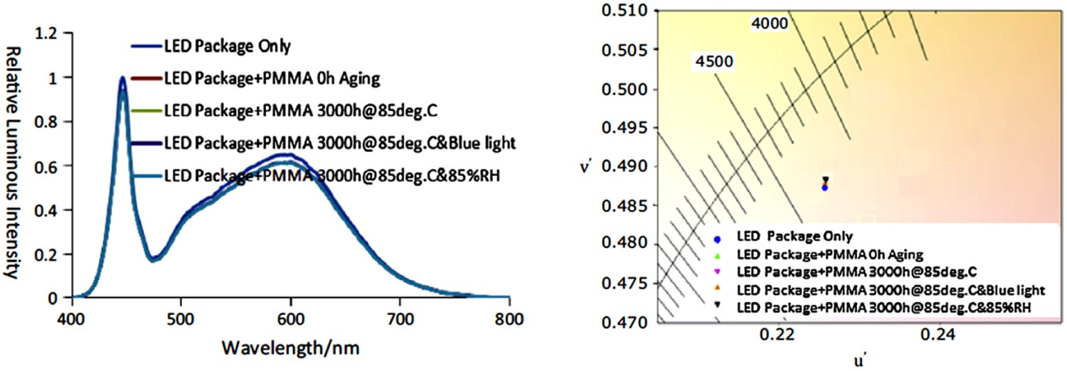
Figure 32 illustrates differences between the yellowing of PC and PMMA samples [91]. Yellowing of PC versus PMMA.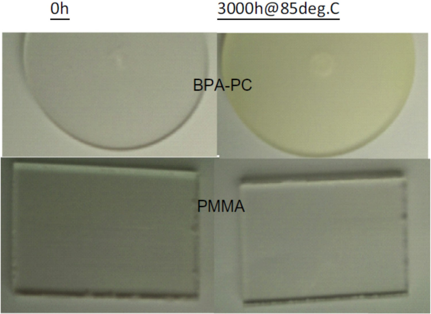
Effect of light
There are a few reports, concerning the photochemical degradation reaction of PMMA, mostly under UV-light exposure [66–103]. The main reported degradation phenomena in PMMA during photo-ageing include complete/partial side chain scissions, light-induced main chain defragmentation, and de-polymerisation [66–103]. Radiant–PMMA interactions, when the wavelength is shorter than 250 nm, reportedly results in the partial/complete scissions in the esther side chain [119–122], whereas in case of higher wavelengths, cross-linking, photo-polymerisation, or curing are more likely to occur [121,122]. Hu et al. [129] examined the photo-ageing reaction mechanism of PMMA under UV exposure. Expectedly, they reported alterations in the refractive index of the polymer. As well, they observed some reductions in the thickness of the aged spin-coated PMMA thin film samples. The observed thickness reduction in aged samples was reported to be in accordance with the measured weight loss. A group of researchers [103–110] examined the influence of radiated light dose (with wavelength in the range 193–308 nm) on the curing, photo-ageing, and photo-polymerisation of PMMA. It was shown that radiant–PMMA interaction reactions also depend upon the irradiation dose. At low irradiation dose regime, radiant-induced curing is likely to take place which results in the cross-linking of two neighbouring esther side chains. By increasing the irradiation dose, radiant-induced curing reaction is replaced with the side chain scissions, which in turn is accompanied with an increase in the refractive index of PMMA. The spectrometric investigations yield the scheme of the main laser-induced photochemical reactions in PMMA as shown in Figure 33. The complete side chain is separated from the main chain. This photochemical reaction of Norrish Type I occurs left from the carbonyl group [110]. Simplified degradation scheme of irradiated PMMA [110].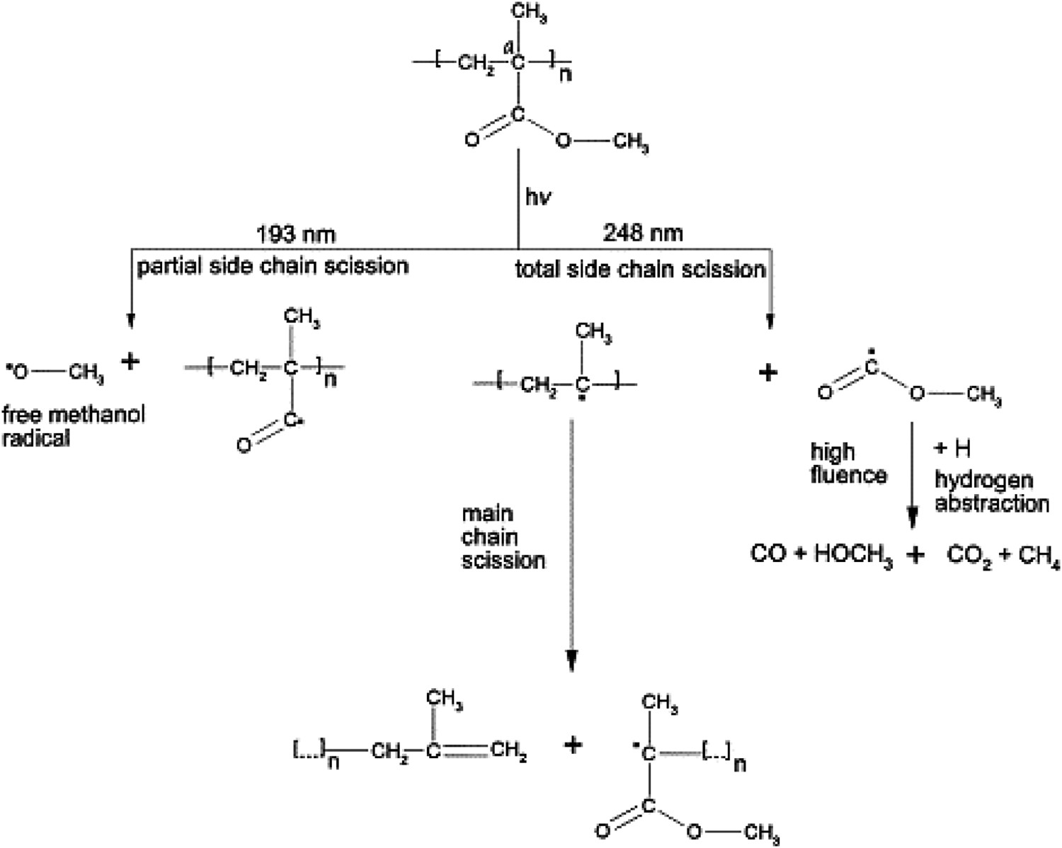
Degradation of epoxy
Effect of temperature
There are many reports [147–161], addressing degradation of optical materials (more importantly lens and reflectors) in LEDs, under different stresses, including temperature, UV/Visible light, ionic contaminations, and humidity. Thermal degradation of an epoxy resin, prepared by reaction of 2,2-bis(4'-hydroxy phenyl)propane (bisphenol-A) with 1-chloro-2,3-epoxy propane(epichlorhydrin), was studied [138]. Thermal degradation at temperatures higher than 320°C results in brittle and insoluble residues. Above 340°C, cross-linking is associated with the decomposition of the residue, and this, in turn, results in the formation of phenolic compounds in combination with other complex products of comparatively high molecular weights [138]. The organophosphorus oligomer, poly(DOPO-substituted hydroxyphenyl methanol pentaerythritol diphosphonate) (PFR), in this case, was synthesised by means of the polycondensation between 10-(2,5-dihydroxyl phenyl)-9,10-dihydro-9-oxa-10-phosphaphenanthrene-10-oxide (DOPO-BQ) and pentaerythritol diphosphonate dichloride (SPDPC). Results confirmed that the flame retardancy and thermal stability of silicone can dramatically be improved if it is mixed with PFR [143]. It was also shown that PFR can slightly increase strain-to-failure of epoxy, which is expectedly accompanied with a minor decrease in its mechanical strength. Based on the obtained results, it was postulated that the thermal degradation of EP/PFR compound takes place via two different temperature-dependent mechanisms. Thermal degradation of EP/PFR hybrid is either due to the decomposition of phosphate or that of aromatic structure.
Effect of light
Jung et al. [170] examined the influence of combined electro-thermal stresses (250 mA/DC at 85°C) on the degradation of optical properties of white GaN-based LEDs (phosphor-converted). Results showed a very fast kinetics of degradation of optical outputs of the device. After 300 h of exposure, they observed 340 K increase in the colour temperature as well as a substantial decrease in the luminous flux (by a factor of 0.43). It is postulated that the mentioned degradation of optical properties is originated from the temperature-induced discolouration of packaging material. As well, non-radiative recombination defects formed under the influence of the current, play a prominent role.
Figure 34 illustrates the influence of thermal ageing at 55 and 105°C on the discolouration of epoxy in LED. While ageing at 55°C has not induced any yellowing, that at 105°C has resulted in a slight yellowing [29]. Influence of ageing at (a) 55°C and (b) 105°C for 6000 h on the discolouration of epoxy in LED [29], reproduced with permission from authors.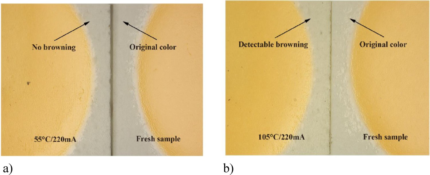
Effect of moisture
Hydrothermal ageing is known to be a major life-limiting and degradation-accelerating factor in epoxy resins [145].
In addition to heat and light effects in discolouration, humidity can also have an accelerating effect on the kinetics of yellowing in EMC used in some LED packages [29]. Figure 35 shows an example in which the effect of humidity on the yellowing of EMC is investigated. The sample in the wet high temperature (95°C) operation lifetime (WHTOL 95°C/95%RH) showed slightly more yellowing the one which is only thermally aged at 105°C (HTOL 105°C). Influence of humidity of the yellowing of EMC [29], reproduced with permission from authors.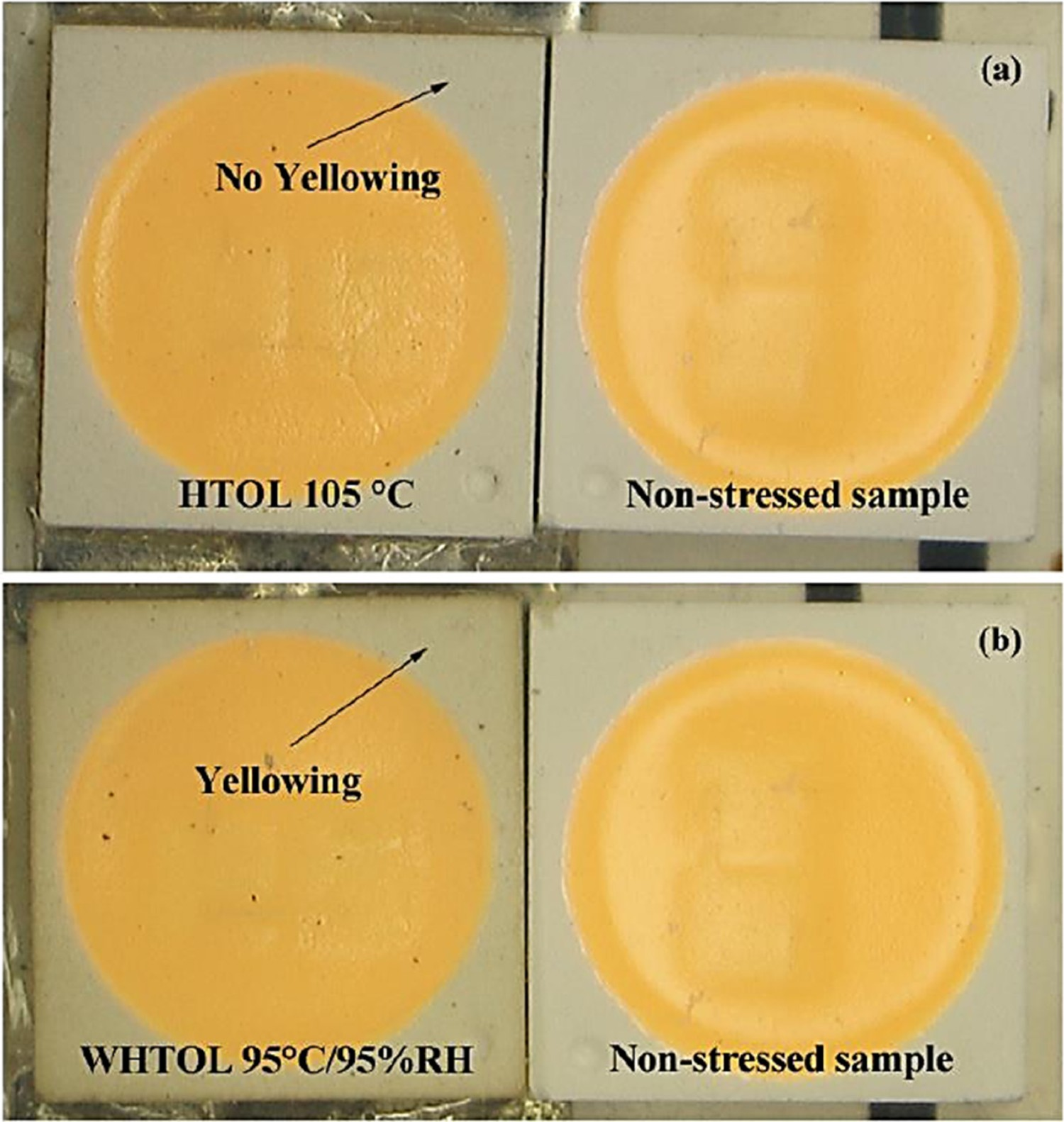
Degradation of phosphor
The efficiency of the phosphor is dependent on temperature; the higher the temperature, the lower is the efficiency. This phenomenon is known as phosphor thermal quenching. Phosphors, used in white LEDs, have basically relatively low thermal quenching [177]. Phosphorescence and fluorescence are two fundamental mechanisms of light generation, with the former having a comparatively longer emission pathway (longer lifetime at the excited state). Phosphor thermal quenching can induce chromaticity shifts due to the relative reduction in the phosphor light output. Increasing temperature is associated with an increase in the probability of non-radiative transition which can cause a chromaticity in pc-LED devices to shift towards blue light and the broadening of spectral power distribution [178,179]. Another important issue concerning phosphor is the temperature at the interface of phosphor particles and the surrounding binder matrix. The temperature at the phosphor/binder interface can be up to 30–50°C more than the junction temperature of the LED. The higher temperature of the phosphor-binder layer is due to the heat generated in the phosphor (e.g. Stokes losses, light absorption), thermal energy from the LED, and the lack of effective heat dissipation. This will obviously have implications for the rate of chromaticity shift in LEDs. This slightly higher temperature at the interface can induce discolouration and cause decohesion and cracking; all having significant negative contributions to the lumen and chromaticity maintenance.
Conclusions and future prospect
This paper tries to give an overview of different failure mechanisms in LED devices. Most of the mentioned failure mechanisms are related to LEDs, used in the lighting market. The lighting market for LEDs, in particular, is expanding rapidly with a market share that is expected to grow to almost full coverage in 2020. The packaged LED revenue was reported at $14.4B (billion) for 2013 with a projection that the total will reach $25.9B in 2018 (Ref: www.ledmagazine.com). Lighting accounts for ∼20% of the global electrical energy use. Knowing that LEDs consume 75% less energy, compared to traditional light sources, their impact on the global energy consumption is enormous and obviously extremely important most of the mentioned failure mechanisms are related to lighting for indoor applications. This paper is a comprehensive review of optical materials-related failure mechanisms. The main focus of this paper is on the chromaticity shift which is directly related to chemical reactions and structural changes in LED optical components. Optical components in LED-based products undergo different degradation reactions during service, which can obviously have implications for chromaticity shifts. So, chromaticity shifts can be controlled and postponed, using materials which are structurally and chemically more stable. Each material has its own characteristic optical properties and failure modes. Different optical materials and their contribution to LED-based product failures are systematically reviewed in this paper. It is also shown that light exposure, temperature, and humidity have significant contributions to the structural and chemical changes, and in turn on the ageing of optical polymers, used in LED-based products. LEDs are increasingly used in outdoor applications as well. When it comes to outdoor applications, especially in harsh environment conditions, other failure mechanisms, including UV radiation or ionic contaminations, should be taken into consideration. Not much is known about the failure mechanisms of LEDs in harsh environment conditions. Future research activities should focus on this important issue. There are other important market domains for LEDs, including health care, mobile electronic devices, and automotive. Failure mechanisms in each of these applications might be different. Specific studies need to be done to evaluate exact failure mechanisms in different applications. Future developments in LED devices are very much dependent on how heat generation in devices is managed. Temperature has a big influence on the kinetics of degradation. Innovative device packages enabling lower working temperature will increase LED lifetimes. Further investigations are required to improve reliability and life time assessment models, in order to overcome several active failure mechanisms and link to life time assessments.