
Abstract
Powder metallurgy (PM) of titanium is a potentially cost-effective alternative to conventional wrought titanium. This article examines both traditional and emerging technologies, including the production of powder, and the sintering, microstructure, and mechanical properties of PM Ti. The production methods of powder are classified into two categories: (1) powder that is produced as the product of extractive metallurgy processes, and (2) powder that is made from Ti sponge, ingot, mill products, or scrap. A new hydrogen-assisted magnesium reduction (HAMR) process is also discussed. The mechanical properties of Ti-6Al-4V produced using various PM processes are analyzed based on their dependence on unique microstructural features, oxygen content, porosity, and grain size. In particular, the fatigue properties of PM Ti-6Al-4V are examined as functions of microstructure. A hydrogen-enabled approach for microstructural engineering that can be used to produce PM Ti with wrought-like microstructure and properties is also presented.
Nomenclature
grain boundary α
primary α
0.2% offset yield strength
standard electrode potential
per cent, elongation (tensile test)
per cent, reduction area (tensile test)
per cent of theoretical density
Introduction
As the ninth most abundant element in the earth’s crust, and fourth among structural metals, titanium has been a fascinating metal to mankind for more than half of a century. Titanium has three unique properties: it has a high specific strength and the same magnitude of strength as that of steel; it is the most biocompatible metal, making it a common selection for biomedical implants; and it is the most corrosion resistant common metal, making it an ideal choice for maritime applications. Particularly for our modern society and other automobile-dependent nations around the world, titanium would be an ideal structural metal to replace steel in vehicles, but there is one thing that stands in the way: cost. Although markets fluctuate, Ti in general is at least 20 times more expensive than carbon steel and approximately 4–5 times more expensive than stainless steel. The traditional production and manufacturing of Ti follows the same general procedures as steel, including primary metal production, melting and pouring of alloy ingots, forging and rolling to produce mill products, and manufacturing of components or structures from the mill products. Owing to its inherent affinity to oxygen and the associated high cost involved in the fabrication of components using Ti, the buy-to-fly (or yield) ratio, using aerospace industry terminology, is typically 12:1 and often more than 20:1 for parts fabricated from mill products, i.e. plates or bar stocks [1,2]. The buy-to-fly ratio for the F-22 fighter jet is 12.2:1, meaning 82% of the titanium became scrap metal [2]. The unfortunate and unavoidable high cost of Ti is exacerbated in almost every step of manufacturing from mineral to products, as illustrated in Figure 1, and the high cost of parts fabricated using the conventional melt-wrought approach is the primary motivation for research and development of powder metallurgy (PM) Ti [3,4]. Flow chart of conventional melt-wrought and powder metallurgy approaches for manufacturing Ti products.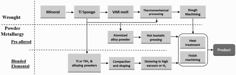
Given its attractive properties and current cost, it is understandable that reducing the cost of Ti production and manufacturing has been a continuing and primary motivation for Ti research. Powder metallurgy, being a near-net-shape manufacturing technology, has been applied to Ti research and development for more than four decades. A comparison of typical PM titanium processes with wrought processes is given in Figure 1. Powder metallurgy includes the production of powders, compaction and shaping of powders, and sintering, as well as post sintering processes to fabricate ready-to-use components. Because of its capacity to streamline processing and reduce the amount of scrap metal produced, the potential of the PM approach for Ti manufacturing is truly substantial. However, a sobering fact is that the commercial successes of PM Ti are still very limited to date, despite decades of research and development and the investment of millions of dollars. Traditionally, wrought Ti is usually chosen over PM Ti because PM Ti parts are either unsatisfactory in view of their mechanical properties and performance, and/or due to high cost.
The first cost factor concerning PM titanium is that of powders. Frequently, the cost of powders is cited as a key hurdle that prevents the development of PM Ti materials and products. For instance, the high cost of powders is often given as a limiting hurdle to the development of Ti products using additive manufacturing (AM). Although less expensive sources of Ti powder are possible, none of them are currently available in the market. Powders can be produced from the by-products of Ti sponge production, i.e. sponge fines. Powders can also be made by hydrogenating the Ti sponge, ingot, or mill product, crushing and/or grinding it to the desired powder size, and then dehydrogenating the material to produce what is known as hydride–dehydride (HDH) Ti powder [5,6]. HDH powder can also be made by hydrogenating and dehydrogenating Ti scrap metals.
Ti alloy powders are typically made by a variety of highly advanced atomising techniques, all of which consist of first making metal alloy, melting the material, and then atomising the molten metal by different techniques. Atomised alloy powders in general have significantly higher costs than HDH powder [7,8]. Additionally, a large number of different technologies have been developed over the recent decades to produce Ti metal, often in the form of powder, including widely known techniques such as the Armstrong [9] and the Fray, Farthing, and Chen (FFC) processes [10]. This review will categorise different techniques and analyse their characteristics.
Although the cost of powder is discussed as the main issue, the cost of manufacturing products from the powders is actually more challenging. There are generally two kinds of approaches for making PM titanium products: the blended elemental (BE) method and the pre-alloyed (PA) method [3,11]. The BE method refers to the pressing and sintering of BE powders. Sintering of the compacted powder is usually carried out in vacuum. The PA method refers to sintering PA powders, which are typically made using the gas atomisation (GA) or the plasma rotating electrode process (PREP). Since PA powders have high hardness, and hence poor press-ability if compacted using a conventional uni-axial cold pressing method, parts are usually made by using pressure-assisted consolidation techniques, such as hot isostatic pressing (HIP). Although PA products generally have better mechanical properties than BE products, the costs of PA products are significantly higher; both the process for making PA powders and the process of hot consolidation (e.g. HIP) are very expensive. Therefore, BE is still the preferred cost-effective approach. However, the mechanical properties of BE parts are often unsatisfactory compared to those of equivalent wrought Ti parts, especially the fatigue properties, due to residual porosity, relatively high oxygen content, and relatively coarse microstructures after sintering [12].
In order to improve BE mechanical properties, most of the efforts reported in the literature have been devoted to developing pore-free BE parts. One simple approach to remove residual porosity is to use post-sintering high pressure processes, such as HIP, which can increase the density to greater than 99.8% [3]. Thermomechanical processes (TMP), i.e. hot/cold working plus heat treatments may also be used to refine grain size and achieve desired phase composition and morphology. The microstructural evolution of PM Ti materials during TMP follows the same physical metallurgy principles of melt-wrought materials. The trade-off of using post-sintering high pressure processes is, of course, an increase in cost, which partially or completely negates the cost–benefits normally associated with the BE method.
With regard to mechanical properties, a key concern of PM Ti materials is their fatigue resistance [12], and again, the primary factor that determines the mechanical properties of Ti alloys is the residual porosity. The fatigue endurance limit is particularly sensitive to porosity, which causes not only low fatigue strength, but also a wide scatter of fatigue data. The next key factor affecting mechanical properties is the oxygen content. Higher oxygen content causes lower ductility and fracture toughness. An additional factor can be the microstructure. The as-sintered microstructure is generally coarse, and therefore undesired from the perspective of mechanical properties. The correlations of mechanical properties to the microstructure, including porosity and grain sizes, as well as oxygen content, will be reviewed in detail in the latter sections of this article.
In short, although PM of Ti has great potential as a low-cost alternative for Ti manufacturing, a number of issues still restrain the use of PM Ti and prevent its industrial acceptance. The most important mechanical property concerns are the fracture toughness and fatigue performance of PM Ti materials, which are often associated with the oxygen and impurity levels of PM materials that tend to be higher than those of wrought materials. It is also a reflection of the fact that PM Ti materials generally have some level of residual porosity unless they are consolidated using high-pressure techniques, either during sintering or through post-sintering treatments.
In view of the different choices of processing approaches and corresponding microstructure and mechanical properties, combined with their associated costs, the challenge to PM Ti technology is not merely to achieve a property target, but rather to achieve a property target without increasing cost. High-performance Ti materials, by either wrought or PM processes, are available today at high costs. The research and development of PM Ti should focus on developing methodologies and processes to reduce cost without compromising mechanical properties. In other words, the challenge is to increase the performance to cost (P/C) ratio.
This article provides a comprehensive and critical review of PM titanium technology. The earlier sections of the paper categorise and analyse different powder production technologies, and latter sections continue with the examination of compaction and sintering technologies and the dependence of mechanical properties on microstructural features that result from different processes. Based on the knowledge of processing technology and mechanical properties, we provide possible technical pathways to maximise the P/C ratios.
Titanium powders as products of extractive metallurgy processes
There are many methods for the production of Ti metal powder. These methods can be classified into two categories. In the first category, Ti powder is made as the product of extractive processes that produce primary metal by reducing titanium tetrachloride (TiCl4) or titanium dioxide (TiO2). In the second category, Ti powders are made from Ti sponge, Ti alloy ingots, Ti mill products or Ti scrap metals. For each of these two categories, there are a large number of techniques described in the literature; however, only a few have been commercially deployed. There are also a number of published reviews of production methods for titanium [3,7,8]. One of the more comprehensive reviews is provided in a publicly available, but not journal-archived publication by EHK Technologies [13]. As the first, and critical, step of powder metallurgy, this section categorises different techniques, and highlights the basic methodology of selected techniques in each category. Details of each technique are beyond the scope of this article, but they are referenced in the bibliography.
Processes for making titanium powder directly as products of extractive metallurgy processes include those of making Ti from TiCl4, purified TiO2, and/or upgraded titanium slag (UGS) with more than 90% TiO2 content. UGS is the product of carbothermal reduction of titanium ore such as ilmenite. Naturally occurring rutile and synthetic rutile also belong to this category of raw materials. These processes can be further classified into two groups: (1) thermochemical processes, and (2) electrochemical processes. Each of these two categories is discussed as follows.
Thermochemical processes
Thermochemical production of Ti involves the reduction of a precursor with a reductant. There are two main precursors: TiCl4 and TiO2. TiCl4 is a liquid at room temperature and atmospheric pressure, but it is easily vapourised at moderate temperatures. Using TiCl4 as the precursor to produce Ti metal has the advantage that all of the undesired impurities in TiCl4 can be removed by distillation, which enables the production of highly purified Ti metal. However, the purification processes to produce TiCl4, including the high-temperature chlorination process from TiO2-bearing minerals, involve a series of highly energy-intensive and costly processes [14]. Motivated by the aim to avoid the high-temperature chlorination process, there have been a number of investigations involving the use of commercial TiO2, titania slag, synthetic rutile, or UGS, as the precursor material [15–26]. Intuitively, TiO2 would be a lower cost precursor than TiCl4 if the high-temperature chlorination step could be avoided. However, the precursor is not the only factor that affects the cost of Ti. The differences in the inherent energies of the reduction of either TiO2 or TiCl4, and the selection of reductant also affect the final cost of Ti metal.
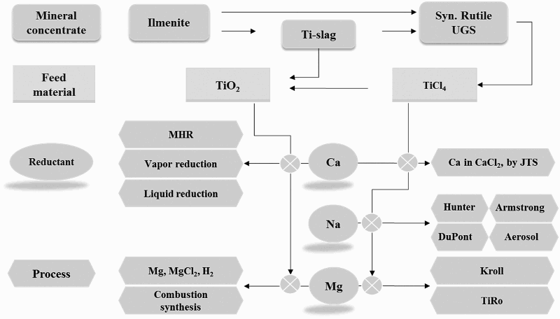
Theoretically, free energy-based Ellingham diagrams for a metal’s reaction with oxygen and chlorine (Figure 2(a,b)) are the basis for the selection of reductants. Based on the Ellingham diagrams [27], there are three possible reductants for the reduction of either TiO2 or TiCl4, namely Mg, Na and Ca. Based on thermodynamic feasibility, Figure 3 shows multiple potential thermochemical routes for the production of Ti metal from the precursors using Mg, Na, or Ca as reductants. Ellingham diagrams: the formation of (a) oxides and (b) chlorides [27]. Thermochemical reduction routes to produce Ti metal through various reductants.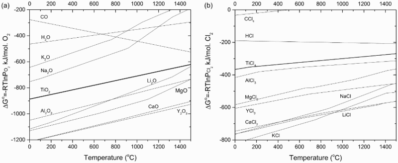
Thermochemical processes based on the reduction of TiCl4
Processes based on the reduction of TiCl4 using Mg
Commercial production of Ti primary metal is usually carried out in either the Kroll or the Hunter processes. The Kroll process is dominant in industry today. The Kroll process relies on the reduction of TiCl4 using magnesium, while the Hunter process uses sodium to reduce TiCl4. The product of traditional Kroll and/or Hunter processes is Ti sponge, which is the standard Ti primary metal that is commercially available today for melting and manufacturing.
In the Kroll process [28,29], as shown in Figure 4, Ti is produced by the reaction of TiCl4 with Mg. TiCl4 is produced by chlorination of Ti slag with the assistance of petroleum coke at 800–1000°C in a fluidised bed. However, impurity oxides in Ti slag are also chlorinated, and thus the crude TiCl4 has to be further purified to produce refined TiCl4 prior to Mg reduction. Illustration of the main processing steps of the Kroll process: (a) chlorination and (b) reduction of TiCl4.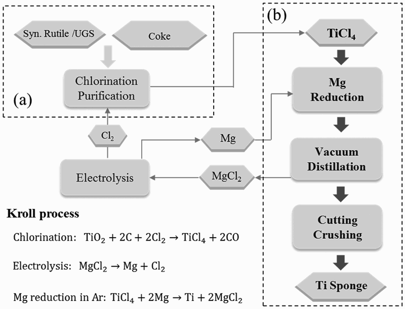
Purified TiCl4 is fed into the reactor and brought into contact with molten Mg. The Mg reduces TiCl4 to Ti, and MgCl2 forms. The Ti nucleates and Ti sponge grow from the bottom, as well as along inner walls of the reactor. As the reaction progresses, MgCl2 and Mg vapour are recovered through an outlet port. The product of the reduction, which is Ti sponge with considerable MgCl2 and residual Mg, must be distilled in vacuum (0.1–1 Pa) at a high temperature of 1000°C for days at a time to ensure the removal of residual Mg, MgCl2 and other volatile species. For a 10 ton batch, the distillation may take 90 h, due to the difficulty of supplying heat to the interior of the container for Mg and MgCl2 evaporation [30]. Furthermore, the vacuum separation is followed by a long period of cooling. To date, the largest facilities can produce 10 ton of titanium per reaction container; however, one cycle takes more than 10 days, i.e. 1 ton of Ti per day. Based on one estimate, the energy consumption of the distillation can be nearly 70% of the total energy consumption of the entire Kroll process from upgraded Ti slag to sponge metal [31]. This is illuminating with regard to the cost of Ti sponge, and subsequently the cost of powders. It shows that the cost of purifying the metal is one of the key drivers of cost, in addition to the cost of the precursor and reductant.
As mentioned earlier, the majority of Ti primary metals used globally by industry today are produced using the Kroll method. Ti-sponge, however, is not Ti powder. It is not a ‘powder production method,’ although the Kroll process does produce what is classified as ‘sponge fines’ that may be used directly as powder. Metallic Ti sponge (Figure 5(a)) is the primary product of the Kroll process, but this material can also be crushed using mechanical means to produce powders. Ti-sponge is also used as the raw material for making Ti powder using other methods. For example, it is used as the starting material to make HDH powder, which will be discussed in the next section. Therefore, the Kroll process is the starting point for understanding several other powder production processes. SEM micrographs of CP-Ti or Ti–6Al–4V powders by different processes: (a) Kroll (sponge fine), (b) Armstrong, (c) HAMR, (d) FFC [64], (e) HDH, (f) PREP and (g) plasma atomisation.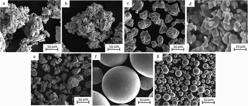
After nearly half of a century of commercial development and optimisation, the Kroll process is firmly established as the industry standard today. However, there have been continuous R&D efforts for decades to reduce the cost of the process. One of the approaches of these efforts has been to develop a continuous process using the same chemistry as that of the Kroll process. TiRO is a prominent example [32], and was developed and reported by the Commonwealth Scientific and Industrial Research Organization (CSIRO) in Australia. The process has two major steps: reduction of TiCl4 in a fluidised bed by Mg powder, and vacuum distillation to remove the MgCl2 byproduct and Mg.
In addition to the TiRO process, there are a few other processes that are chemically similar to the Kroll process [14,33–35], all of which attempt to develop a continuous process. Deura et al. reported a technique to produce Ti powder by injecting TiCl4 gas into Mg through MgCl2 molten salt in order to spatially separate the Ti product from Mg by molten salt [33]. During this process, the reaction takes place at the interface of the molten Mg and MgCl2.
Another continuous process is based on vapour-phase reduction to produce powder [35]. In this process, liquid TiCl4 carried by argon gas reacts with magnesium vapour that is generated by vaporising Mg wire to form a mixture of Ti, MgCl2, and Mg powder. The product powder is removed from the gas stream by an electronic precipitator, and Ti powder product is further separated from Mg and MgCl2 by either vacuum distillation or leaching. A drawback of this process is that the size of the particles is in the sub-micrometer range, which is too fine for capture and separation. The fine powder also picks up a significant amount of oxygen and nitrogen during subsequent processing.
Yet another continuous two-step process was developed by Van Vuuren et al. [34]. In this process, TiCl4 is partially pre-reduced by Ti powder or Mg to generate a TiCl2-bearing MgCl2 solution. The TiCl2 is then further reduced by molten Mg dispersed in the molten MgCl2 to produce Ti powder. Some of the product is recycled to the TiCl4 pre-reduction step, and the remainder is withdrawn from the reactor to undergo subsequent steps of sedimentation and distillation. There are also many challenges for this process, one of which is that the particle size of Ti powder produced by this process is very fine, which makes it prone to oxygen pickup [34].
Comparison of the characteristics of different processes based on the reduction of TiCl4 with those of the Kroll process.
aReported chemical composition is quoted from the corresponding references. They are not meant to be the limit of the method.
Processes based on the reduction of TiCl4 using Na
The most well-known process based on the reduction of TiCl4 using Na is the Hunter process. The Hunter process is similar to the Kroll process in that it is a thermochemical process based on the reduction of TiCl4 to produce Ti [36]. Similar to the Kroll process, the Hunter process was commercialised during the middle of the twentieth century, and for a considerable period of time it was one of the two main commercial processes for production of Ti. However, commercial production of Ti sponge using the Hunter process has gradually come to a halt over the years because it became clear that the Hunter process is not economically competitive with the Kroll process. There are many reasons for this, but a primary obstacle is that to produce 1 mol of Ti by the reduction of TiCl4, it takes 4 mol of Na, while only 2 mol of Mg are required per mole of Ti. And, the production of Na by electrolysis is at least as costly as that of Mg. These issues make Na processing more expensive than using Mg.
However, the Hunter process is also recognised as a process that can be used to make not only Ti sponge, but also Ti powder [29,37]. During the Hunter process, TiCl4 and Na are placed in a reactor, either simultaneously, or TiCl4 is fed gradually into the reactor where Na is already preloaded. The process is typically carried out at temperatures above 800°C, at which Na and NaCl are always in their molten state. Ti forms at the surface of the molten pool, where TiCl4 gas contacts with Na. Ti crystals then form and settle to the bottom of the liquid pool. Depending on the operational parameters, some of the Ti particles will connect and fuse together to form Ti sponge, while others will settle as Ti powder. In fact, the process operating parameters may be adjusted such that most of the Ti particles are separated from each other; therefore the main product of the process is powder, rather than Ti sponge. The NaCl also provides protection, preventing the Ti particles from being exposed to air, and thus the purity of the powder produced by the Hunter process is often superior.
Typical particle sizes of Ti powder produced using the Hunter process are −60 or −100 mesh. However, there is a substantial fraction (12–19%) of fine powders that will fall through −325 mesh. Oxygen, nitrogen, carbon, and iron contents can all meet industry specifications, and are lower than those produced by the Kroll process [29]. The characteristics of the powder, as well as the processes based on Na reduction, are given in Table 1 to compare with processes based on Mg reduction.
Again, similar to the reduction of TiCl4 using Mg, there have been a number of reports on the development of continuous processes based on the same chemistry as that of the Hunter process, to reduce cost. The Armstrong process is an example. It is one of the few R&D processes that garnered considerable attention and investment, due to its promise to reduce the cost compared to batch processing [38]. Indeed, the main advantage of the Armstrong process is that it is a continuous process, pumping molten sodium to meet gaseous TiCl4 in the reactor. Figure 6 illustrates the basic aspects of the Armstrong process. The resulting Ti powder and NaCl are removed from the reaction zone by the flowing sodium and the growth of Ti powder, which could trap unreacted raw material and co-products, can be inhibited. After the unreacted liquid Na is filtered out and the residual Na is distilled from the filtrate, the Ti powder is collected in a solution by washing out the salt. The product of the Armstrong process can be characterised as mini sponges [39], i.e. particulates with micro porosity (Figure 5(b)). For subsequent PM processes, powders made from the Armstrong process need to be milled to smaller sizes. Illustration of the main processing steps of the Armstrong process.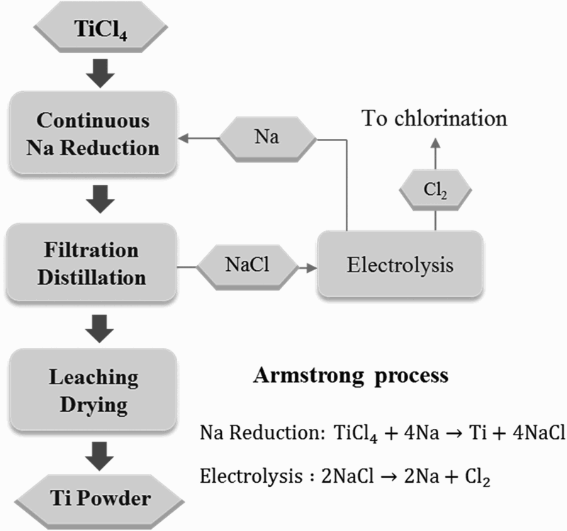
Another process based on sodium reduction of TiCl4 was developed by the Albany Research Center (ARC) of the US Department of Energy. The ARC process is similar to the Armstrong process in that it is also a continuous process [40], however, the ARC process is a two-step process that first reduces TiCl4 to TiCl2, and then to Ti.
Thermochemical processes based on the reduction of TiO2
As shown in Figure 3, in addition to the processes described above, which all focused on the reduction of titanium tetrachloride (TiCl4), there is another subcategory of processes that focus on the reduction of titanium dioxide. These processes are characterised by metallothermic reduction of TiO2. Reductants that can be used include Ca and Mg, and thus there are calciothermic and magnesiothermic methods, respectively.
Calciothermic methods are promising, principally because Ca is a very strong reducing agent. Four different forms of Ca have been investigated as options for calciothermic reduction, including CaH2 (e.g. the metal hydride reduction (MHR)) [41,42], vapour-Ca (e.g. the preform reduction process) [17], liquid-Ca [18], and electronically mediated reduction (EMR) [19,20]. The MHR process dates back to 1945, and the most notable work was reported by Borok [43] in 1965 and Froes et al. [44] in 1998. Calcium hydride was used to reduce TiO2 directly, and reportedly, there is a commercial operation in Russia based on this process. However, concrete information about its commercial reality is not readily available.
The preform reduction method was developed by Okabe et al. in Japan [17]. In this process, reductant Ca is placed underneath but not in contact with TiO2. TiO2 is pre-fabricated in the form of blocks mixed with a flux of either CaO or CaCl2, and the preform is then reacted with Ca vapour at temperatures between 800 and 1000°C. The calcium vapour reacts with TiO2, leaving Ti and CaO. Fine titanium powder is obtained by leaching the product with acid. The Ca content of the powder is a concern, and the oxygen level was reported to be around 3000 ppm [45].
Suzuki et al. reported a method of calciothermic reduction of titanium oxide in molten CaCl2 [22]. The TiO2 was reduced by liquid calcium floating on the molten salt. The CaCl2 plays the role of transporting Ca to react with TiO2, and dissolves the CaO by-product to push the reduction reaction forward. An oxygen level of 1000 ppm was reported after the reduction for 6 h using 5–7 mol-% Ca–CaCl2 at 900°C by this method [22].
Comparison of the characteristics of the processes based on the reduction of TiO2.
Note: Reported chemical composition is quoted from the corresponding references. They are not meant to be the limit of the method.
Magnesiothermic reduction refers to processes that use Mg to reduce TiO2. The initial concept of using Mg to reduce TiO2 dates back to 1964 as reported in a US patent [46]. Rutile was mixed with Mg granules along with MgCl2 as flux. The reaction mixture was held at about 750°C for a long time in a hydrogen atmosphere to reach nearly complete reduction, and Ti metal powder with an oxygen content as low as 1.7 wt-% was obtained. In more recent decades, a number of other reported research investigations explored this approach using either mixtures of Mg with TiO2 or using Mg vapour to reduce TiO2 [24,47,48]. In one approach an exothermic mixture was placed on top of the sample as an igniting agent to stimulate a self-sustaining reduction. The measured temperature for combustion reduction can reach 1600°C or higher. The Mg reduction of TiO2 at 750°C has also been reported [25], however, an accurate oxygen composition after reduction was not provided.
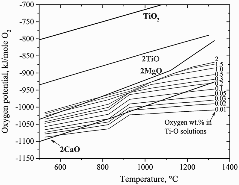
Thermodynamic analysis showed that there is a lower limit of oxygen content in the powder at approximately 1.9 wt-% when Mg is used as the reductant [46,49]. In fact, this is true for both Mg and Ca with respect to their equilibrium with Ti–O solid solutions. As the Ti–O phase diagram (Figure 7) shows [50], solubility of oxygen in α-Ti can be up to 14.3 wt-%. The lower limit of oxygen content in Ti to which Mg or Ca can remove oxygen from Ti depends on the temperature and oxygen partial pressure, as shown in Figure 8. This figure also shows that the lower limit is much lower when Ca is used as opposed to Mg, which is understandable since Ca is a stronger reducing agent. A new direct reduction of the Ti-slag (DRTS) process using Mg was recently reported by Fang et al. [51] The Mg reduction is directly carried out on UGS, which is composed of more than 95% TiO2. The reduction process is conducted in a hydrogen atmosphere to form titanium hydride (TiH2) deliberately, which is followed by leaching in aqueous solutions to purify the TiH2 powder. Titanium-oxygen phase diagram [50]. Free energy-based Ellingham Diagram, comparing relative stability of Ti-O solid solutions with MgO and CaO [56].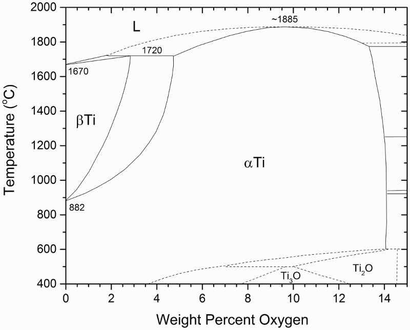
An alternative route of this process is to prepare purified TiO2 first, which is then subjected to a two-step hydrogen-assisted magnesium reduction (HAMR) process (Figure 9) [52,53]. A low-cost method based on alkaline roasting at relatively low temperatures followed by a hydrolysis process is used to produce highly purified TiO2. Purified TiO2 can also be obtained commercially by using the sulphate process or the chloride process [54]. Compared to commercially available TiO2 pigment, the particle size of TiO2 produced by the alkaline roasting process is much larger, but costs significantly less than does the chloride process which produces TiO2 pigment from TiCl4 [55]. Illustration of the main processing steps of the HAMR process. Purified TiO2 used in HAMR can be prepared by using the alkaline roasting process, the chloride process or the sulphate process.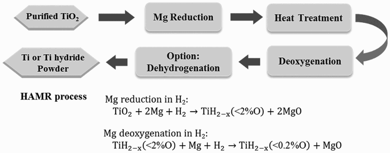
In order to produce Ti powder with extremely low oxygen content, the HAMR process is designed to include the following three key elements: (1) the use of hydrogen atmosphere; (2) the use of molten salt; and (3) the adaptation of a two-step process consisting of the main reduction step and a deoxygenation step. There are advantages of using hydrogen. First, hydrogen helps to destabilise the Ti–O system, increasing the thermodynamic driving force for Mg to react with Ti–O [56]. Another benefit of using hydrogen is the formation of titanium hydride, rather than Ti metal, during the reduction process. Titanium hydride is known to be more impervious to oxidation in air compared to α-Ti, which makes it easier to handle the material after reduction and control oxygen content in the final product.
Another key feature of the HAMR process is the use of molten salt, especially Mg bearing salt such as MgCl2. It was found to be necessary to use molten salt to facilitate the reaction and greatly improve the kinetics of the reduction process.
The chemical composition of the powder produced using the DRTS/HAMR process [52].
Deoxygenation of Ti metal powder
As discussed above, there is a limit to which the oxygen content can be reduced by using Mg as the reducing agent. This limit is thermodynamically shown in Figure 8. The solubility of oxygen in α-Ti can be up to 14.3 wt-% [50]. In order to reduce oxygen content to less than 0.2 wt-%, as required by many professional standards and industrial specifications, the oxygen in the solid solution can be removed by a deoxygenation process. Deoxygenation can be used not only as a part of the metal production process, but also as a method to remove residual oxygen from any Ti powder when the oxygen content is higher than the required specifications.
Conceptually, the reduction of TiO2 and the removal of oxygen content in Ti can thus be expressed in two separate reactions:

A few calciothermic processes have been reported for deoxygenating titanium and titanium alloys [57–60]. Most of these operate by reacting with molten calcium, through solid–liquid or solid–gas reactions. For example, RMI (now part of Arconic) patented a process that operates above 900°C for reducing oxygen in Ti–6Al–4V powder [59]. Note that in this process, which is also industrially known as the deoxygenation in the solid state process, Ti is in the solid state, while the reducing agent Ca is in the molten state. Okabe et al. [60] tried deoxygenation of titanium in molten CaCl2 at a temperature above 900°C. Because of the high temperature, the evaporation of Ca metal and CaCl2 could not be avoided unless sealed reactors were used. By using these methods, it is also difficult to recover the Ti powder because of sintering between particles and caking of the entire powder mixture with Ca or the melt of Ca/CaCl2. Oh et al. [58] experimented with solid–gas contact by conducting the reaction at 700–830°C in high vacuum (∼6 × 10⁻³ Pa). However, the significant loss of calcium in vacuum might be a serious problem. The use of high vacuum is also not preferred for large-scale industrial operations.
Recently, Xia et al. developed a low-temperature molten salt deoxygenation process which can reduce the oxygen level in titanium to less than 1000 ppm from a level as high as 14.0 wt-%, which is the solubility limit of oxygen in α-titanium [61,62]. Calcium is used as the deoxygenating agent in this process. The molten salt facilitates the dissolution of solid Ca into the melt below its melting point of 845°C to aid the formation of Ca2+ ions, which react at the surface of the particles to cause the deoxygenation. The calcium halide bearing salt creates a low-temperature molten salt condition for deoxygenation. Being able to deoxygenate Ti at moderate temperatures (<800°C) has many advantages. For instance, Ti powders do not sinter to each other during the deoxygenation process as easily as they would if the temperature were greater than 900°C. The Ti powder after being subjected to the deoxygenation process can be readily separated, retaining their original size and morphology. Lower operating temperature also makes it easier to select the reactor materials, which has significant implications for the commercial viability of the process.
In addition to Ca, Zhang et al. reported recently that Mg can also be used to deoxygenate Ti–O solid solution alloys at low temperatures (600–800°C) [56]. Thermodynamically Mg can reduce TiO2 or α-Ti that contains a significant content of O. When O is dissolved in an α-Ti lattice, forming a Ti–O solid solution, Ti–O can be more stable than MgO, depending on the oxygen content and the temperature. For instances, MgO is less stable than Ti-2 wt-% O at temperatures above ∼780°C, or less stable than Ti-1 wt-% O at temperatures above ∼600°C, and less stable than Ti-0.5 wt-% O at all temperatures above room temperature, as shown in Figure 8. The new deoxygenation approach is based on the thermodynamic tuning of the relative stability of MgO and Ti–O by introducing hydrogen. It was found that Ti–O can absorb hydrogen to form Ti–O–H solid solutions in a hydrogen atmosphere, and the oxygen potential in the Ti–O–H solid solution is lower than that in the initial Ti–O, making it less stable than MgO. That is, hydrogen can destabilise Ti–O by forming a Ti–O–H alloy, making it possible to reduce O content in Ti–O by using Mg. This thermodynamic destabilisation changes the reaction between Mg and Ti–O to form MgO from a situation where it is thermodynamically impossible to one where it is favoured. Hydrogen in the deoxygenated powder can subsequently be removed via a thermal dehydrogenation treatment, leaving pure Ti or Ti alloy powders with an oxygen content as low as a few hundred ppm. In other words, hydrogen is used as a temporary alloying element to assist the removal of oxygen from Ti or Ti alloy by Mg.
Most recently, an electrochemical technique for deoxygenation of Ti in molten MgCl2 was reported by Okabe et al. [63]. By applying voltages between a Ti cathode and C anode immersed in molten MgCl2, the activity of MgO was decreased and the activity of Mg was increased. An example was given showing that the oxygen content in a Ti sample was reduced from 1000 to less than 200 ppm.
Electrochemical processes
Electrochemical methods are another main route for the production of Ti. There are quite a number of electrochemical processes that have been under development. However, only a brief review of those developments can be described in this section. A more comprehensive review of the production of Ti by electrochemical processes can be found in the literature [64]. Most of the research and development work has focused on the electrolysis of TiO2, with some work on the electrolysis of Ti
x
O
y
C, and TiCl4. Among all reported work on the electrolysis of TiO2, the most well-known process was first reported by Chen, Fray, and Farthing [10,65], as shown schematically in Figure 10. This process is called as the FFC Cambridge process. It operates in a molten salt medium, normally in the temperature range of 800–1100°C. CaCl2 is used as the salt, since CaCl2 can dissolve and transport the oxygen ion, and it is cheaper and less toxic than the alternatives, such as BaCl2 and LiCl [66]. Illustration of the main processing steps of the FFC process.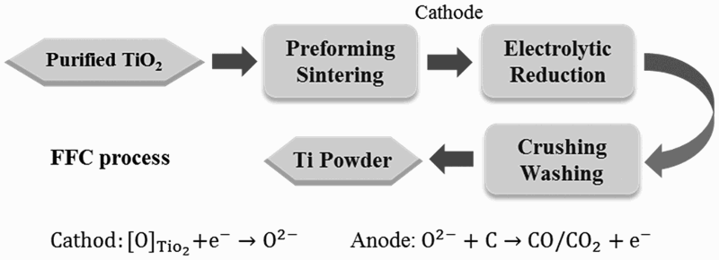
A typical FFC cell includes a graphite anode and an oxide cathode. Because TiO2 is an insulator, it was generally believed that it would not be possible to reduce TiO2 by electrolysis. However, Chen et al. found that when a small amount of oxygen is removed from TiO2, it forms Magnéli phases (TiO2−x
) which are highly conductive [10]. Further electrolysis removes the residual oxygen from the magnelli phases, where the oxygen ions dissolve in the electrolyte, and is then removed as CO2 or CO. Schwandt et al. studied and reported on the reaction mechanisms [67–69]. They believed that Ca2+ from the salt first reacts with TiO2 to form calcium titanate, CaTiO3. Suboxides of titanium (Ti4O7, Ti3O5, Ti2O3, and then TiO) are subsequently produced. TiO is eventually formed and is further reduced by electrochemical deoxidation to Ti(O), the solid solution of oxygen in titanium. The overall reaction steps have been reported and outlined by the following equations [69]:


Figure 5(d) shows that the final product has a porous sponge-like morphology, composed of globular Ti particles attached to each other due to sintering. In the original FFC method, preformed TiO2 pellets were used as precursors [70,71]. More recently, reports have indicated that free-flowing oxide powders can also be used as the feedstock. Furthermore, it has been reported that it is also possible to reduce granules of synthetic rutile or naturally occurring rutile ore [72]. Because both natural and synthetic rutile contain impurities such as Fe, Al, and Si, it was suggested that a new titanium alloy powder that contains some of those elements can be produced using this method [73].
In addition to making commercially pure titanium (ASTM Grade 4), a wide range of other titanium alloys, such as Ti–Mo [74], Ti–Nb [75], Ti–6Al–4V [76–78], and TiNi [79,80], have also been produced by the FFC process. The characteristics of the FFC process, as well as other research electrochemical processes, are compared in Table 2.
An apparent advantage of the FFC Cambridge method is that it is a one-step process, and it does not use Mg as the reducing agent, which makes it potentially cost effective compared to the Kroll or other processes that use Mg to reduce TiCl4 or TiO2. This is because Mg is one of the main cost factors in the Kroll process. As mentioned above, the FFC method can also be used for direct production of alloys, potentially offering cost savings in another manner. However, the FFC process also has challenges, including low current efficiency and the possibility of incomplete/partial reduction of TiO2 [70,81]. The current efficiency depends on many factors, including the parasitic reactions involving carbon and the formation of calcium, which can dissolve into the salt near the end of electro-deoxygenation. From an end-product quality perspective, there is little published information to date on the quality of the powders produced by using the FFC process. Bertolini et al. [82] reported that powder produced by the FFC process at a multiple kg scale had 0.29 wt-% O, 0.07 wt-% C, 0.014 wt-% Fe, 0.13 wt-% Ca and 0.06 wt-% Cl, provided as an example of the composition of Ti powder made from pure TiO2 using the FFC process. However, the report does not necessarily represent the best capability of the process, which is still under development.
Other examples of the electrolytic processing of TiO2 in published reports include: the OS process, based on the combination of the reduction of TiO2 by Ca and electrolysis to regenerate Ca in a molten CaCl2 salt by Ono et al. [21,83–86]; an electrolytic process using carbothermic reduction of TiO2 compound and Ti x O y C as the anode [87–89], the electrolytic process to convert titanium slag to liquid titanium metal [90]; and the solid oxide membrane (SOM) process using a solid-oxygen-ion conducting yttrium-stabilised-zirconia membrane separating the anode from ionic TiO2-containing flux (MgF2–CaF2–TiO2) [91,92].
Yet another reported work is the electrolysis of titanium oxycarbides (TiO x C y ) [93] or oxycarbonitrides (TiO x C y N z ) [94] represented by the Chinuka process. In this process, oxycarbide is used as the anode material. The consumable anode materials of TiO x C y or TiO x C y N z are oxidised to titanium ions and simultaneously CO evolves at the anode; thus titanium ions are reduced to metallic titanium at the surface of the cathode through electrolysis in molten salts.
Titanium powders made from Ti sponge, mill products, or Ti scrap
Today, commercially available titanium powders are mostly made using Ti sponge, Ti ingot, Ti mill products, or Ti scrap metals as the starting material. Especially, commercially pure Ti (CP-Ti) powders are available as HDH powder, while Ti alloy powders, e.g. Ti–6Al–4V alloy, are made using the PREP, or other atomisation methods. Brief descriptions of these methods are as follows.
Hydride–dehydride
To produce HDH powder, either Ti sponge, Ti ingot, mill products, or Ti scrap can be used as the raw material [5,6]. When scrap metals are used, it may be either CP-Ti or Ti alloys such as Ti–6Al–4V, and the scrap must first be cleaned to remove foreign materials. The hydrogenation is typically accomplished using a batch furnace that can be operated in vacuum and/or hydrogen atmospheric conditions. The Ti metal and metal alloys can be easily hydrogenated under one atmospheric pressure of hydrogen at temperatures below 800°C by forming titanium hydride and alloy hydrides. The hydrogenation process and the equilibrium hydrogen content are a function of both the temperature and pressure of hydrogen. Figure 11 shows the equilibrium pressure of hydrogen as a function of molar content of hydrogen at different temperatures [95]. Because the equilibrium pressure of the Ti–H system increases as temperature increases, the driving force for forming hydride increases as temperature decreases, assuming the hydrogen pressure is held constant. Therefore, in reality, after Ti is heated to a set temperature such as 700°C, the hydrogen content will reach equilibrium at a specific temperature and increase during cooling. Exact hydrogen content of the hydride can, however, vary. Especially in the case of hydrogenated Ti–6Al–4V alloy, hydrogen content is typically less than what is expected based on the Ti–H phase diagram. New hydrogenation methods were developed to make low-cost TiH2 powder by ADMA Products, Inc., in which hydrogenated titanium is produced during the Kroll process [96–99]. Titanium sponge can be hydrogenated in the same vessel after the reduction/distillation cycle during cooling to form titanium hydride [96]. Titanium hydride can also be produced after the reduction of TiCl4 by magnesium and hydrogen [99]. The pressure-composition-temperature curves of the Ti–H system [95].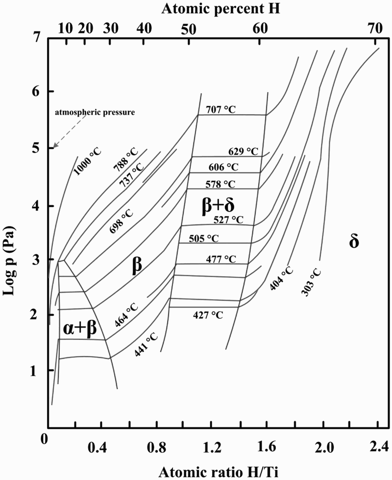
One of the advantages of forming hydride as an intermediate step is that the hydride can be easily crushed to different particle sizes ranging from −325 to −60 mesh. A variety of powder-crushing and milling techniques may be used including: a jaw crusher, ball milling, or jet milling. Finer particle sizes are easy to obtain, but rarely used because oxygen content increases rapidly when the powder is finer than 325 mesh. Powder finer than 325 mesh also poses more safety challenges.
After the titanium hydride powders are crushed and classified, they are placed back in the batch furnace under vacuum or argon atmosphere to dehydrogenate and produce Ti metal powder. The powder can be passivated upon completion of both the hydrogenating and dehydrogenating cycles to minimise exothermic heat generated when exposed to air. Figure 5(e) illustrates the typical morphology of HDH Ti powder.
A major advantage of HDH powder is that it is relatively inexpensive. The costs of the hydrogenation and dehydrogenation processes add only a moderate amount of cost to that of input material, and the purity of HDH powder can be very high, as long as the raw material’s impurities are controlled. The oxygen content of HDH powder has a strong dependence on the input material, the handling processes and the specific surface area of the powder [5]. The main disadvantages of HDH powder include: the powder morphology is irregular, and the process is not suitable for making virgin alloyed powders or modification of alloy compositions if the raw material is from scrap alloys.
Atomisation
In general, atomisation processes are used for making alloyed powders, and PA Ti feedstock is generally used as the starting material for atomisation. Atomised alloy powders are typically used for making components using HIP. As mentioned previously, it is generally believed that alloyed powders are not suitable for cold compaction using conventional uniaxial die pressing methods because the inherent strength of the alloyed powders are too high, making it difficult to deform the particles in order to achieve desired green density.
Because almost all atomisation processes are used for producing relatively spherical shaped powders, atomised Ti alloy powders are the most common choice for AM using selective laser or electron beam melting techniques [100,101]. Spherical powders are also required for manufacturing Ti components using metal injection molding (MIM) techniques [102]. Typically, AM and MIM processes require particle sizes of powders to be in the range from a few to 100 µm to ensure good flowability of the powder, which is essential for AM and MIM operations. However, atomisation processes usually produce powders with a wide particle size distribution, from a few to hundreds of micrometers. The yield of powder under −325 mesh (44 µm) is usually low depending on the specific atomisation technique, but the yield is a major factor contributing to the high cost of usable powders.
Key features of different atomisation techniques.
Gas atomisation
GA of titanium was originally developed by Crucible Materials Corporation in the 1980s [103,104]. The basic configuration of the GA process is shown in Figure 12(a). GA usually produces powder in a wide size range (up to 500 μm) [105]. Close-coupled gas atomisation (CCGA) is the latest technique, improving the production yield of relatively fine particles (<45 μm) [106,107]. However, there is a risk of yttrium contamination due to the use of laminated composite pour tubes made of Y2O3. Although GA is, generally, a mature technology, there are a few issues worth noting. There are considerable interactions between droplets while they cool during flight in the cooling chamber, causing the formation of satellite particles. Owing to the erosion of atomising nozzle by the liquid metal, there is potential for contamination by ceramic particles, and there may also be argon gas entrapment within particles. Since molten titanium is very reactive to most common metals and ceramics, electrode induction gas atomisation (EIGA) was developed by ALD Vacuum Technologies to produce ‘ceramic-free’ powder, in which the melt is not in contact with the ceramic lining material or the crucible [108,109]. A PA rod is used as the feed material. In order to minimise possible contamination pickup during atomisation, a gas-atomisation apparatus with a Ti coating on the inner wall of the atomisation chamber and other components in the flow path was designed and developed by FMW Composite Systems, Inc. [110]. Schematic diagrams of (a) GA process and (b) PREP.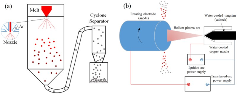
Plasma rotating electrode process
The PREP is one of the most recognised techniques for making Ti alloy powders, and avoids the potential contamination issues posed by ceramic nozzles [111,112]. The basic configuration of this process is shown in Figure 12(b). The feedstock must be precisely machined titanium alloy bars, which are used as the anode that rotates at roughly 15 000 rev min−1 while being melted by the plasma arc. The rotation of the electrode causes molten droplets to spin away from the anode under centrifugal acceleration. The liquid droplets form spherical shapes spontaneously to minimise surface energy. The cooling rate is typically less than 100°C s−1, and particle sizes of PREP powder typically range from 50 to 350 μm [112], which is ideal for HIP applications. The PREP powder is shown in Figure 5(f).
Plasma atomisation
Plasma atomisation is described here to represent processes that use PA wire as the feed material [113,114], which is a significant cost contributing factor. The Ti alloy wire is melted in a plasma torch, and a high velocity plasma flow breaks up the liquid into droplets which cool rapidly, with a typical cooling rate in the range of 100–1000°C s−1. Plasma atomisation produces powders with particle sizes ranging from 25 to 250 μm. In general, the yield of particles under 45 μm using the plasma wire atomisation technique is significantly higher than that of conventional GA processes. The plasma-atomised powder is shown in Figure 5(g).
Production of spherical Ti powder
Making spherical powder is not a specific processing technique. However, it is singled out here because it is in high demand for AM using selective laser sintering or electron beam sintering techniques. Titanium alloy, Ti–6Al–4V in particular, is one of the prime examples of AM metals. AM is a manufacturing technique that is most valuable for making complex shaped parts or systems that are custom designed for special applications which do not need large quantities of material or large production runs. These features match well with the characteristics of Ti alloys, because Ti is mostly used for applications with unique and stringent requirements that only Ti can meet. Examples include aircraft components and biomedical implants that are custom made for each individual patient. Spherical powders are also necessary for MIM with Ti alloys. As a forming technique, both AM and MIM of Ti are described later in this article.
Chemical compositions of Ti–6Al–4V powder as required by various industrial standards.
In general, spherical Ti powders that are available in the marketplace today are made by either atomisation methods or plasma spheroidisation of non-spherical powders. Atomised Ti powder can be made by all of the atomisation techniques mentioned above. However, the published literature suggests that several techniques are primarily being used: PREP, GA, CCGA, EIGA, and plasma atomisation. These techniques are discussed in section ‘Atomization'. A key consideration for selecting one technique over another is the yield of the powders that meet the requirements for size and size distributions for AM or MIM. The required particle sizes are generally in the range of <45 μm for MIM or AM based on selective laser sintering, and 45–106 μm for AM based on electron beam processes. One of the key advantages of using the PREP process is to avoid using nozzles that are often made from high-temperature ceramic materials. Ceramic inclusions from the erosion of the nozzles must be avoided for Ti alloys.
There has been some reported research effort towards making spherical Ti powder more affordable. Among these efforts, the plasma spheroidisation of powders is a relatively new but popular technique [120]. Plasma spheroidisation of powders has been applied to a variety of different powders, including refractory metals such as tungsten [121]. During plasma spheroidisation, the metal powder is melted by a plasma torch and forms molten droplets, which solidify to form spherical solid powder before reaching the bottom of the reactor chamber [121]. A unique characteristic of plasma spheroidisation is that the particle sizes do not change during plasma processing. Plasma-spheroidised particles typically have the same nearly perfect round shape as the other atomised powders [6,122]. Another example is a continuous method during which low-cost Ti sponge fines, HDH powder or electrolytically produced Ti and alloy powders are fed through a plasma transferred arc torch to make spherical alloy powder [88]. In addition to spheroidising, or producing, particles in the molten state, there are reports on modifying particle shape in the solid state by mechanical means [123,124]. The flowability of irregularly shaped powders was reportedly improved by removing sharp angles on the particles through high-speed blending or high shear milling.
Recently, a new approach, called granulation-sintering-deoxygenation (GSD), for making spherical Ti powder was developed by Fang et al. [125,126]. Using this approach, spherical Ti powders can be made by forming spherical granules composed of fine Ti particles. The spherical granules can be sintered to obtain solid spherical Ti powder. Figure 13 illustrates key steps of this process. Schematic illustration of the GSD process for making spherical titanium alloy powders from scrap or hydrogenated Ti sponge [125]. (Reproduced with permission.)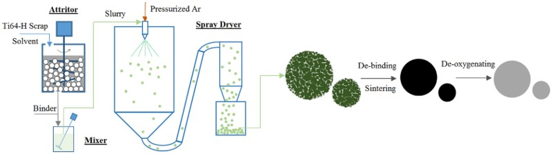
There are a number of key issues when using this process to make spherical Ti powder. First, to produce spherical powders of less than 45 μm, the particle sizes of the initial fine powder must be less than a few microns. The finer the initial particle size, the better the granules will be with respect to surface finish and sinterability. However, the limiting factor is that the oxygen content, as well as the content of other interstitial elements, in the final Ti powder increases with a decrease in the initial particle size. Thus, there is a balance between the considerations of achieving spherical morphology and minimising the content of interstitial elements in the final spherical powder. Second, the oxygen content of the powder depends strongly on the powder handling and processing steps. Oxygen content will inevitably increase with the granulation, sintering, and other associated processes. Therefore, a deoxygenation step is necessary. Results showed that the oxygen content of the spherical powder can be lowered to 0.1 wt-% or below, which is sufficient for many applications. The third concern is that particles may bond to each other during sintering. Therefore, measures must be taken to prevent or eliminate the sintering of particles to each other. Figure 14 shows the morphology and the cross-section of the spherical powder. SEM micrographs of spherical Ti–6Al–4V powder by the GSD method [125]. (Reproduced with permission.)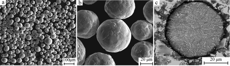
Sintering and consolidation of Ti powders and the resulting microstructures
Ti powder compacts can be sintered using a variety of processes, including pressureless sintering under vacuum or inert gas, as well as pressure-assisted consolidation techniques such as vacuum hot pressing (VHP) and HIP. Of course, the microstructure of the sintered Ti alloy depends on the specific process and the processing parameters employed, as well as the feedstock powder. The following sections will focus on the effects of sintering processes on porosity, purity, and microstructure (grain size and morphology), and analyse how these three factors affect the mechanical properties of sintered Ti alloys. It should be noted that this review does not delve into the sintering mechanisms or kinetics of sintering, but rather the focus is on the effects of PM processing on the microstructure and properties of Ti alloys.
Issues of residual porosity and purity were the primary focus of the earliest research into Ti powder metallurgy. Impurity elements in Ti alloys include: oxygen, chlorine, carbon, and nitrogen. A significant advance in the BE approach has been achieved with the use of low chloride Ti powder [127]. Chlorine or chloride contents as low as 200 ppm, which is typical for inexpensive Ti powders, have been reported to adversely affect the densification process during sintering [128]. Profound improvement in the as-sintered density has been achieved simply by using powder with less than 10 ppm chlorine [129]. Although the effects of chlorine, carbon, and nitrogen are important, they can generally be controlled during Ti sponge and powder production processes. Additionally, sponge can be produced with very low oxygen content. Nonetheless, oxygen content is the most challenging problem during powder processing and sintering.
As with other reactive metals, a native oxide layer is often present on the surface of titanium powder particles. However, this oxide layer, which tends to retard sintering of aluminium and magnesium alloys, can dissolve at elevated temperatures and does not impede the sintering of Ti [130]. Mo et al. reported that the oxide layer is effectively removed at approximately 700°C [131]. It should be noted that there is some disagreement in the literature regarding the exact temperature, though it is consistently reported that this effect occurs below 1000°C [132,133]. Ti also exhibits comparatively strong diffusion bonding at relatively moderate temperatures. In fact, solid state diffusion bonding at a temperature below the β-transus (995°C for Grade 5 Ti–6Al–4V [134,135]) has been used by Rolls Royce to join Ti sheet in the production of turbine engine blades [136]. For these reasons, Ti readily densifies at temperatures above 1200°C, though residual porosity remains when sintered using conventional pressureless sintering processes.
Regarding the issue of porosity, it has been demonstrated that the residual porosity may be effectively closed via pressure-assisted consolidation (e.g. HIP) or thermomechanical processing (TMP, e.g. forging) after sintering [129,137,138]. However, incorporating these energy-intensive post-processing steps drives up cost [4].
Additionally, refining the as-sintered microstructure produced by traditional sintering processes is almost impossible because of the lack of stored energy to drive recrystallisation. This is particularly true for α + β Ti alloys (e.g. Ti–6Al–4V), which have a tendency to form coarse lamellar microstructures during sintering. The coarse microstructures are detrimental to mechanical properties, especially the fatigue strength, but recent breakthroughs have identified mechanisms to reduce the residual porosity and refine the microstructure of as-sintered Ti–6Al–4V (section ‘Sintering of TiH2').
This article will highlight the microstructure as a function of the process, laying the groundwork for examining the relationships between processing, microstructure, and properties in the subsequent sections.
Pressureless sintering of Ti metal powder
Pressureless sintering includes inert gas and vacuum sintering, which are both reported to have been used for sintering Ti. However, vacuum is far more commonly used than inert gas sintering for Ti.
The first experiments aimed at sintering Ti sponge were performed by Kroll in 1937. During these experiments, Kroll used a low-pressure argon atmosphere (
Vacuum has long been considered the ideal sintering atmosphere for Ti, owing largely to the work performed by Dean et al. [140] in the 1940s. However, any process which requires vacuum is inherently limited to batch processing. For this reason, continuous sintering processes under protective gases have long been investigated. All non-noble protective gases (e.g. nitrogen) react readily with Ti and will compromise the purity and mechanical properties of the alloy if used for sintering. With respect to cost, argon is the only feasible option of the noble gases. In fact, argon sintering has been used commercially by DuPont, dating back to the 1950s, to produce PM Ti components [141]. Additionally, Toyota uses argon sintering to produce PM Ti metal matrix composites [142].
Owing to Ti’s strong gettering of oxygen and nitrogen, commercial grades of argon may result in unacceptable pickup of these elements during sintering. Methods are available for purifying argon in situ, such as flowing the gas over Ti chips or sponge at temperatures over 800°C [143]. Another approach utilises specialised ‘OXYNON’ sintering furnaces produced by Kanto Yakin Kogyo (Japan). These furnaces use a carbon-fiber sintering belt, designed to remove oxygen from argon during sintering [144]. OXYNON furnaces have reportedly been used to continuously sinter Ti since 2002 [130]. Heaney and German reported interesting results in 2004 from a study in which CP-Ti was sintered using a vacuum furnace versus an OXYNON furnace under argon [145]. During the study, identical sintering experiments were performed in each type of furnace and repeated for three different starting powders. It was reported that the samples sintered in the OXYNON furnace had lower oxygen, nitrogen, and carbon content than identical samples sintered in the vacuum furnace. The lower carbon content is a surprising result, considering the fact that the OXYNON furnace employed carbon hardware at high temperatures. However, the samples were separated from the carbon belt with zirconia plates and covered with molybdenum sheets. It was determined that the small amount of carbon introduced by the vacuum oil residue in the vacuum furnace was greater than that picked up from the carbon hardware in the OXYNON furnace. Each sample set had similar density after sintering for both the OXYNON and vacuum-sintered samples. The OXYNON-sintered samples exhibited similar ductility to the vacuum-sintered samples in all but one sample, which had significantly lower ductility. However, the poor elongation of this particular sample was attributed to contamination by sodium-reduced titanium powder next to it in the sintering furnace. The vacuum-sintered samples exhibited consistently higher strength for each sample set by approximately 100 MPa. This fact was not discussed by the authors in the context of the sintering atmosphere, though it could be due to the increased interstitial content of the vacuum-sintered samples.
For BE powders of α + β alloys, temperatures of 1200°C or higher are usually necessary to both facilitate densification and allow for sufficient homogenisation of the alloying elements [146,147]. For α + β alloys, this is well above the β-transus (995°C for Grade 5 Ti–6Al–4V [134,135]). Therefore, at a typical sintering temperature, the microstructure consists entirely of equiaxed β grains on the order of hundreds of microns in diameter and with a homogenous distribution of the alloying elements. As the material is cooled relatively slowly, preferential nucleation of α grains along the prior β grain boundaries results in a continuous layer of ‘grain boundary α’ (α
GB). As the material is continually cooled, α grains grow into the bulk of the β grains as colonies of parallel plates with a (110)
β
||(0001)α Burgers relationship (Figure 15) [134,148,149]. The size of the colonies, as well as the individual α lamellae, is determined by the cooling rate. Faster cooling forces the nucleation of more α grains, which results in a finer microstructure. The high sintering temperatures and relatively slow cooling rate of conventional pressureless sintering, therefore, consistently result in a coarse lamellar microstructure for PM Ti–6Al–4V (Figure 16(a,b)). Phase transformations during cooling of Ti–6Al–4V from above β-transus [149]. (Adapted with permission.) Micrographs of press and sintered Ti–6Al–4V: (a) OM, α is light phase and β is dark phase [11], and (b) SEM, α is dark phase and β is bright phase. (Reproduced with permission.)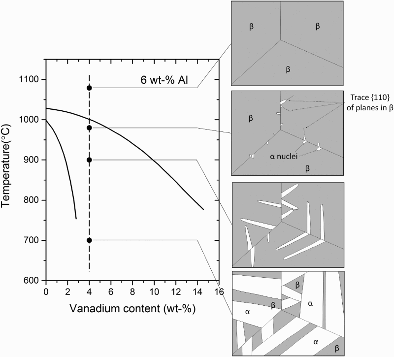
Even with 100% density and low interstitial content, a coarse lamellar microstructure is undesirable with respect to mechanical properties; particularly fatigue performance [150]. The Burger relationship of the α grains with the parent β grains results in a common basal plane for entire α colonies. Since faceted fatigue fracture is most common along the basal plane in these alloys, a fracture along the basal plane can readily propagate across colonies [148]. Therefore, the typical as-sintered PM Ti–6Al–4V microstructure is unacceptable for critical applications, especially those requiring high fatigue performance due to the fact that it contains large α colonies.
The typical as-sintered PM Ti–6Al–4V microstructure is similar to the ‘β-annealed’ microstructure that results from super-transus heat treatment in wrought processing (WP) [134]. Traditionally, this coarse lamellar microstructure is refined through plastic deformation during TMP, which produces high dislocation densities that serve as a driving force for recrystallisation. Microstructural evolution, however, can also be driven by introducing temporary alloying elements (i.e. hydrogen), which make new phase transformations possible. These phase transformations are the basis for thermohydrogen processing (THP) and hydrogen sintering and phase transformation (HSPT). This is discussed in detail in section ‘Sintering of TiH2 in H2’.
Vacuum sintering is traditionally the most common method of sintering Ti. The typical as-sintered density of PM α + β Ti alloys (e.g. Ti–6Al–4V) sintered in vacuum is approximately 98% theoretical density (TD) [11]. Oxygen content in sintered materials is typically greater than 0.2 wt-% [11], depending on the particle size and size distributions [151]. The typical as-sintered microstructure of vacuum sintered Ti–6Al–4V alloy is a relatively coarse lamellar structure [3,11].
Pressure-assisted consolidation
Pressure-assisted consolidation techniques are typically necessary for sintering PA powders. This is because the inherent strength of PA powders makes compaction of these powders much more difficult. In fact, it has been reported that to produce a green compact of Ti–6Al–4V from −100 mesh powder to 84% TD required 965 MPa for PA powder and only 413 MPa for BE powder [152]. In the same study, it was found that the PA powder required higher sintering temperatures to reach a similar as-sintered density. It was theorised that diffusion of the alloying elements in BE compacts helped densification during sintering. For these reasons, PA powders generally require pressure-assisted consolidation such as HIP or VHP to achieve similar consolidation as pressureless sintered BE powder. PA Ti–6Al–4V sintered via pressure-assisted techniques has also been shown to exhibit improved mechanical properties, particularly fatigue performance, in the as-sintered material when compared with the BE approach [11].
The preferred powder for most pressure-assisted processes is spherical powder that has been produced by GA or the PREP [153]. The improved flowability of these powders is necessary to sufficiently fill complex near-net-shape geometries. As mentioned previously, these powders are generally expensive [105]. Therefore, in order to be commercially viable, any process using PA powder usually needs to be near-net-shape to offset the cost of the powder.
Hot isostatic pressing
HIP is the most common method used for consolidating PA Ti powders [11,105]. Initial incarnations of the HIP process for producing Ti alloys utilised ceramic molds prepared similarly to investment casting molds [154,155]. During this process, the shaped ceramic molds were filled with titanium powder and placed inside of a steel can. The steel can was then packed with spherical alumina, evacuated, sealed, and placed inside the HIP. While this provided a relatively simple method for directly producing a shaped part via HIP, it was found that foreign ceramic particles introduced by this process were detrimental to fatigue performance [156]. Therefore, the ceramic mold process has been largely abandoned. Currently, a shaped metal that can be filled with the powder and placed directly inside the HIP is used.
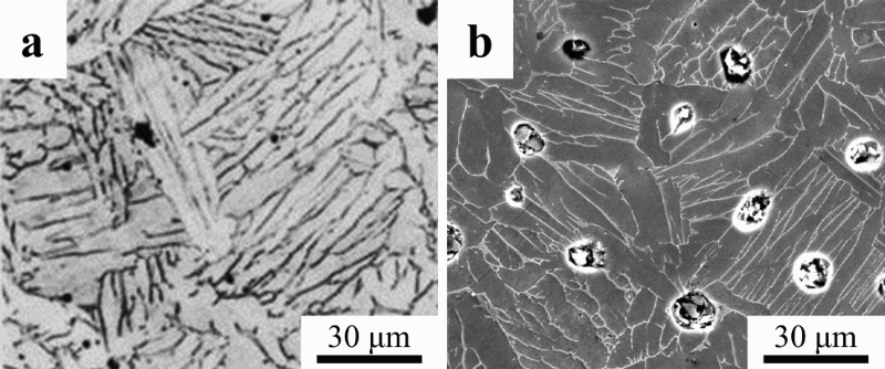
HIP is generally conducted at temperatures between 850 and 1200°C. The isostatic nature of the deformation in HIP densifies the material at lower temperatures than pressureless sintering. Therefore, consolidation can be achieved at temperatures below the β-transus, thereby avoiding the coarse lamellar transformed β microstructure that is the result of conventional sintering processes (section ‘Pressureless sintering of Ti metal powder’). When consolidated via HIP below the β-transus, Ti–6Al–4V tends to have a microstructure with a mixture of elongated α platelets and apparently equiaxed α grains (Figure 17(a,b)) [105,157]. It should be noted that while these microstructures seem to show two different α morphologies, they are unlike the bi-modal microstructures typically seen in WP. The equiaxed grains in a bi-modal microstructure produced via WP tend to be located at the triple points of the α colonies [134]. However, in the HIP microstructures shown here, grains with similar morphology appear in groups. Microstructure of Ti–6Al–4V produced from PA powder using HIP: (a) optical micrograph of GA powder pressed at 954°C [105], (b) SEM (back scattered) micrograph of PREP powder pressed at 1020°C [157], and (c) SEM (back scattered) micrograph of PREP powder pressed at 1040°C [157]. (Reproduced with permission.)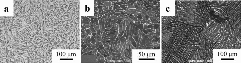
After HIP processing, the material may be forged, or processed with another form of TMP, to refine the microstructure and improve the mechanical properties [158]. Of course, this option is only viable for the production of mill products meant for subsequent working (e.g. rolling, extrusion, etc.), as the significant plastic strain required to drive recrystallisation is not near-net-shape compatible. Additionally, as mentioned above, TMP is inherently energy-intensive and subject to lower yields. Therefore, including TMP after HIP processing could significantly increase the embodied energy (total energy per mass of product produced) and decrease the performance-to-cost ratio of the final component [4].
The microstructure of the material after HIP is strongly dependent on the temperature used during HIP processing. Zhang et al. reported on samples that were consolidated via HIP for 4 h at 880, 930, and 1020°C [157]. While the samples consolidated via HIP at 880°C exhibited the finest microstructure, the best ductility (18–21%EL) and fatigue performance (500 MPa at 107 cycles) was reported for the samples consolidated at 930°C [157]. Fractography of a tensile sample consolidated at 880°C showed crack propagation along the prior particle boundaries. Therefore, despite the finer microstructure, the decreased mechanical properties of the samples consolidated at 880°C are likely the result of arrested diffusion and poor inter-particle bonding due to the low temperature. This demonstrates that an important trade-off between microstructural evolution and diffusion during sintering must be considered with regard to mechanical properties. When the sample was consolidated at 1020°C, which is above the β-transus, a coarse fully lamellar structure was produced (Figure 17(c)). As discussed in section ‘Pressureless sintering of Ti metal powder’, any time Ti–6Al–4V is heated above the β-transus and cooled slowly, it is effectively β-annealed, producing this microstructure [134]. Therefore, performing HIP above the β-transus effectively eliminates any microstructural benefits that are gained by pre-alloying the powder.
In the literature, various microstructures in PA Ti–6Al–4V obtained by varying the processing parameters, such as temperature and pressure, are reported. PA powders often exhibit a martensitic microstructure within the particles due to rapid cooling during powder production (e.g. PREP, GA, etc.) [157]. Thus, the microstructures of PA Ti–6Al–4V after HIP are characteristic of a phase transformation from martensite α’ to α + β [159]. The as-sintered microstructure after HIP, however, significantly changes with the relationship of the HIP temperature to the β-transus [160]. Performing HIP at a temperature below the β transus leads to a bi-modal microstructure of equiaxed α and transformed β (lamellar α colonies). Zhang et al. proposed that the formation of equiaxed α is caused by the deformation at the inter-particle interfaces during the HIP process, which leads to localised recrystallisation [157]. This leads to grouping of the equiaxed grains along the prior particle interfaces, as shown in Figure 17(b). As mentioned above, this microstructure is different from the traditional bi-modal microstructure produced by working and duplex annealing wrought Ti–6Al–4V, where the equiaxed grains would be located at the triple points of the lamellar colonies. Additionally, characteristics of the starting PA powder also affect the resulting microstructure of the alloy. Higher strain energy stored in the powder can result in a greater degree of recrystallisation and a more equiaxed microstructure, which is preferred for ductility [150].
Vacuum hot pressing
Early work on VHP of PA Ti powders dates back to at least the 1980s [161,162]. However, recent work has been reported on VHP to produce Ti alloys from both PA [163–165] as well as BE powders [163–166]. These studies investigated CP-Ti [165,167], as well as Ti–6Al–4V [163], Ti–3Al–2.5V [166], and Ti–6Al–7Nb [164] alloys.
The four samples shown in Figure 18 are Ti–6Al–4V produced by Bolzoni et al. [163] from a study to compare the microstructure and mechanical properties of Ti–6Al–4V produced from BE and PA powders using VHP. As shown in Figure 18(a), VHP at 900°C for 1 h of BE powder leads to an inhomogeneous microstructure, due to insufficient diffusion of the alloying elements. Therefore, when using BE powders, this method requires sintering temperatures of at least 1100°C to produce a homogenous microstructure. However, when temperatures exceeding 1100°C are used, VHP results in a coarse lamellar microstructure very similar to pressureless sintering or β-annealing (Figure 18(b)). Any type of pressure-assisted consolidation, of course, will result in better densification at lower temperatures. However, with regard to the morphology of the microstructure, there is no apparent benefit of using VHP versus conventional pressureless sintering for BE powder, as higher temperatures are still required to homogenise the alloy. SEM (secondary electron) micrographs of Ti–6Al–4V produced via VHP of blended (BE) and PA powders: (a) and (b) BE pressed at 900°C for 1 h and 1300°C for 30 min, respectively, (c) and d) PA pressed at 900°C for 1 h and 1300°C for 30 min, respectively [163].(Reproduced with permission.)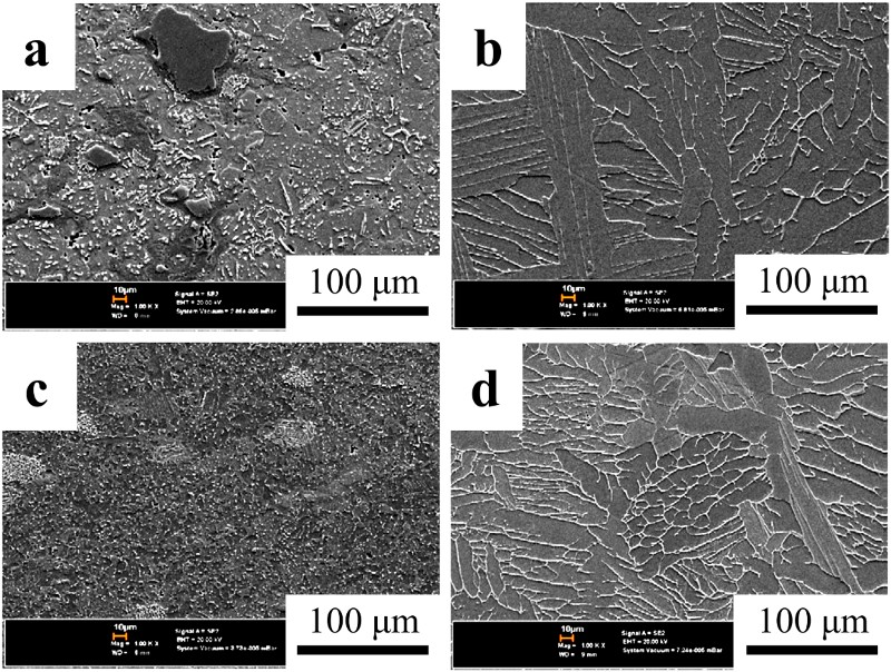
Figure 18(c) shows the microstructure of Ti–6Al–4V produced in the same study by VHP of PA powder at 900°C for 1 h. This experiment resulted in a fine equiaxed microstructure. Because the powder was PA, the microstructure is homogenous, as opposed to the corresponding sample pressed from BE powder at the same temperature (Figure 18(a)). Additionally, the sample had the best flexural strength (∼1600 MPa) and deflection (∼2%) of all the VHP samples presented, as determined by 3-point bend testing. It should be noted that the oxygen content was nearly 0.5 wt-% for this sample, which would account for the high strength and low ductility. For comparison, Figure 19(d) was hot pressed in vacuum at 1300°C for 30 min. As would be expected, performing VHP over the β-transus resulted in a coarse lamellar microstructure for both the BE and PA samples. Flow chart of the generalised CHIP process and a representative micrograph showing the microstructure of Ti–6Al–4V after the HIP step [158]. (Reproduced with permission.)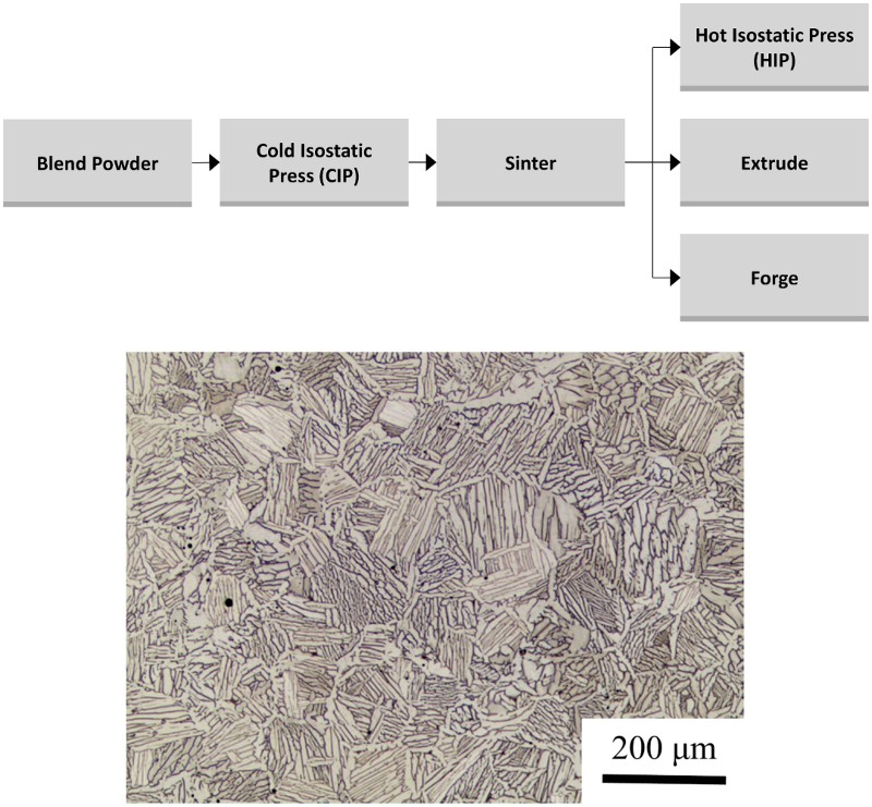
CIP-sinter-HIP process
The CIP-sinter-HIP (CHIP) process is a multi-step PM process in which a green body/preform is produced via cold isostatic pressing (CIP), conventionally sintered under vacuum, and then hot isostatically pressed to close the remaining porosity [158]. A schematic of this process is given in Figure 19. The CHIP process has enjoyed significant commercial attention. In fact, this process is currently reported to be the sole qualified PM production route by the Boeing Material Specification for PM Ti–6Al–4V [168]. Additionally, CHIP has been identified as a possible ‘green’ manufacturing technology for sustainably producing Ti alloys [158,169].
As mentioned, HIP is utilised solely to close the residual porosity after vacuum sintering during the CHIP process. Therefore, the microstructure after HIP is similar to that achieved in conventional pressureless (vacuum) sintered compacts of BE powder. An optical micrograph of Ti–6Al–4V alloy produced via the CHIP process is shown in Figure 19 [158]. As seen, the microstructure is comparable in size and morphology to the lamellar structure produced via conventional pressureless sintering. As also shown in Figure 19, CHIP may also be used with subsequent TMP, such as extrusion and forging [158]. In addition to serving as a forming process, TMP can break up the coarse lamellar grains and facilitate the formation of a refined equiaxed or bi-modal microstructure through recrystallisation of the α grains. However, as pointed out earlier, TMP processes are not near-net-shape compatible, are inherently energy-intensive and, therefore, would increase the cost of the final product.
CHIP, as with other pressure-assisted consolidation, is shown to effectively produce fully dense PM Ti alloys. However, when BE powders are used, sintering temperatures well above the β-transus are required to homogenise the alloying elements. Therefore, the microstructures of PM Ti–6Al–4V produced via CHIP are similar to those available with conventional pressureless sintering. If more expensive PA powders are used, lower sintering temperatures may be used, enabling the formation of different microstructures.
Sintering of TiH2
As discussed in section ‘Hydride–dehydride’, the HDH process is a well-known, commercial process for Ti powder production. HDH takes advantage of the brittleness of Ti hydride to improve comminution behaviour in powder production [7]. However, hydrogenated Ti powder may also be used in PM consolidation processes. The use of hydrogenated Ti powder instead of metallic Ti powder has been shown to result in reduced oxygen content in the sintered alloy (see section ‘Vacuum sintering TiH2’) [170,171]. Additionally, the brittleness of Ti hydride results in a tendency of the powder to crush during cold compaction [172,173]. This has been shown to result in better green density over Ti powder of similar particle size and morphology when using the same compaction pressures. Paramore reported that the relative green densities for compacts produced from −325 mesh (<44 μm) powder of TiH2 and Ti yielded theoretical densities of 83 and 66%, respectively, when compacted at 276 MPa, and 87 and 73% when compacted at 414 MPa [174]. The relative densities reported in this study took into account the different theoretical densities of TiH2 (3.75 g cm−3) and Ti (4.51 g cm−3). Furthermore, improved densification during sintering has been reported when hydrogenated Ti powder is used (see section ‘Vacuum sintering TiH2’) [175]. Finally, because of the reversible nature of the hydrogenation reaction, hydrogen is easily removed from Ti by annealing under vacuum or inert gas [176,177]. For these reasons, there is a long history of using hydrogenated Ti as the feedstock material for PM processes.
The first patent to use Ti hydride powder in a sintering process, filed by Gregory, dates back to the 1960s [178]. This patent describes a method in which Ti hydride powder is used in the production of niobium-based superconductors. Shortly afterwards, a process to produce Ti alloys and metal matrix composites using Ti hydride powder was developed at the United States Army Materials and Mechanics Research Center [179,180]. This process was called ‘decomposition powder metallurgy’ and was first reported in 1970 by Greenspan et al. as a method to produce Ti alloys and metal matrix composites via hot pressing [179]. The first press and sinter process to produce Ti alloys from Ti hydride was patented by Obara et al. in 1976 [181]. In this process, sintering was achieved under vacuum or inert gas atmospheres. Following these pioneering publications and patents, a wide variety of processes have been published and/or patented that use hydrogenated Ti powder. These processes include both pressure-assisted (i.e. hot pressing or HIP) as well as press and sinter methods, and have been used to produce a range of products including Ti alloys [173,182–188], sputtering targets [189], decorative Ti products [190], and shape memory alloys [191].
Vacuum sintering TiH2
Since 2000, a significant amount of work regarding vacuum sintering of hydrogenated Ti powder has been reported by Ivasishin et al. [147,170,175,192–196] and Savvakin et al. [197] It has been reported that a blend of Ti hydride with 10 wt-% 60Al/40V master-alloy powder produced Ti–6Al–4V with 98.5–99.5% TD in the as-sintered state, versus 90–95% when metallic Ti powder was used [193]. Additionally, it has been reported that using Ti hydride produced samples with an as-sintered oxygen content of 0.21 versus 0.39 wt-% when metallic Ti powder was used [198]. This work has led to a series of patented processes for the production of hydrogenated Ti powder, as well as vacuum sintering of these powders to produce Ti alloys and metal matrix composites [96–98,171,199,200].
The sintering profile used to produce Ti–6Al–4V from hydrogenated powder in these studies utilised times and temperatures similar to sintering metallic powder (1200–1350°C for 4 h) [195,201]. Therefore, as expected, this sintering process produces Ti–6Al–4V with a lamellar structure, very similar to that achieved via a typical press and sinter process of Ti blended with elemental or master-alloy powders. Figure 20 is a micrograph showing the as-sintered microstructure of Ti–6Al–4V produced by vacuum sintering Ti hydride powder blended with 60Al/40V master-alloy [201]. This microstructure consists of α colonies in the order of 100 μm across with individual lamellae in the order of 10 μm wide and 100 μm long. Optical micrographs of Ti–6Al–4V produced via vacuum sintering of TiH2 blended with master alloy [201]. (Reproduced with permission.)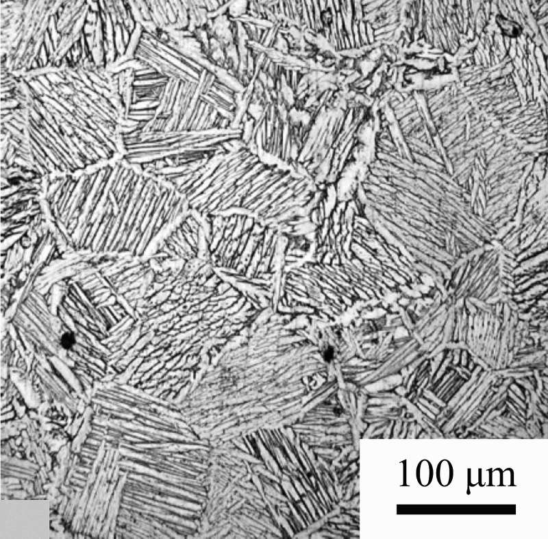
Sintering of TiH2 in H2
Since 2011, a process called HSPT has been developed by Fang, Sun, and Paramore et al. [4,172,174,202–213] HSPT is a multi-step pressureless sintering process, in which Ti hydride or partially hydrogenated Ti powder is blended with master-alloy or elemental powders and sintered under a dynamically controlled hydrogen atmosphere. After sintering, residual hydrogen is removed by annealing under vacuum or inert gas (Figure 21). HSPT takes advantage of the phase transformations in the (Ti-alloy)-H systems to simultaneously refine the microstructure during the thermal cycle. A detailed description of the HSPT processing steps [207] as well as an improved (Ti–6Al–4V)-H phase diagram [210] and descriptions of the underlying mechanisms for microstructural refinement [211] are available in the literature. Schematic representation of the HSPT sintering profile.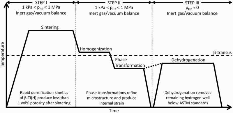
The HSPT process has been specifically developed as a low-cost process to produce high-performance Ti alloys with wrought-like microstructures and mechanical properties. As such, this research has been focused on employing commercially viable low-cost PM processing, including: Low-cost BE powder Conventional cold compaction and pressureless sintering (‘press and sinter’) Only low-cost and near-net-shape compatible processing steps (no TMP such as forging and extruding)
Figure 22 shows the microstructure of Ti–6Al–4V produced via HSPT with and without subsequent heat treatments, as detailed in the literature [208]. An SEM micrograph of the as-sintered microstructure produced via HSPT is shown in Figure 22(a), while Figure 22(b) is an optical micrograph of the same material. In contrast with other Ti PM processing technologies, the HSPT process produces an ultrafine grain (UFG) microstructure with α colonies measuring several microns across and individual α grains measuring several microns long with submicron widths. Additionally, while traditional β-phase sintering produces a coarse lamellar α/β microstructure, the β phase in the HSPT material is finely divided throughout the microstructure. This is a key feature of the HSPT microstructure, as this allows for subsequent pressureless heat treatment steps to produce very fine wrought-like microstructures without mechanical working. Micrographs of Ti–6Al–4V produced via HSPT: (a) SEM of as-sintered UFG lamellar structure, (b) OM of as-sintered UFG microstructure, (c) OM of heat-treated bi-modal microstructure, and (d) OM of heat-treated globularised microstructure [209]. (Reproduced with permission.)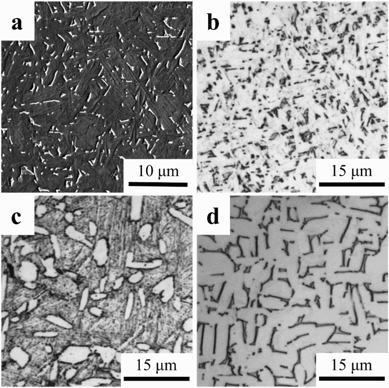
By utilising simple heat treatments on the as-sintered material, very fine wrought-like bi-modal (Figure 22(c)) and globularised/equiaxed (Figure 22(d)) microstructures are possible [208,209]. In either microstructure, the globularised α grains are on the order of 5 μm in width. It should be emphasised that in WP or traditional powder metallurgy, producing fine bi-modal or equiaxed microstructures requires energy-intensive TMP to first break up the coarse lamellar microstructure and produce plastic strain to serve as a driving force for recrystallisation, which produces the equiaxed α grains in these structures [134]. However, it has been proposed that the very fine morphology of the as-sintered HSPT microstructure allows for the formation of globularised α grains without recrystallisation [174,208,209]. Detailed discussions on the specific heat treatments used and the mechanisms behind these phenomena are available in the literature [174,207–209,211,213].
Owing to the microstructures, HSPT Ti–6Al–4V has been shown to have wrought-like mechanical properties as well [174,208,213]. As-sintered UFG HSPT Ti–6Al–4V typically has strength exceeding 1 GPa and ductility exceeding 15%EL. The properties may be application-tailored via simple heat treatments to increase the ductility beyond 20%EL or strength exceeding 1100 MPa. Additionally, HSPT has been shown to have fatigue properties competitive with wrought Ti–6Al–4V [174,213,214].
Special hot consolidation techniques
In addition to the traditional processes detailed in the previous sections, specialised consolidation and sintering processes for the production of Ti alloys have also been reported in the literature. These processes are typically pursued to address the shortcomings of Ti PM, such as coarse microstructures from high sintering temperatures, residual porosity, poor alloying element homogeneity, and inability to cost-effectively produce certain part geometries (sheet and plate).
Microwave sintering
There have been several studies on the heating susceptibility of Ti powders to microwave radiation [215–219], the densification and microstructure of microwave-sintered Ti [218–228], and the resulting mechanical properties [218,220]. However, the heating of Ti by microwaves tends to be erratic [229]. For this reason, several studies have utilised microwave susceptors, such as SiC sample holders, to produce predictable and consistent heating of Ti powders [218–220,222,224–226]. It has also been reported that TiH2 is capable of being heated by microwave radiation without susceptors [230,231] to produce small CP-Ti samples with improved density and mechanical properties compared to those produced from metallic Ti powder [228].
When microwave susceptors are used, the densification of Ti alloys via microwave heating appears very similar to that achieved via conventional pressureless sintering [218,225]. One study reported the production of 99% TD Ti–6Al–4V by using CIP on PA powder at 690 MPa and microwave sintering at 1300°C for less than 1 h [225]. However, it has been reported that elevated sintering temperatures (∼1300°C) are required to facilitate diffusion and produce a homogenous microstructure in Ti alloys [229]. Therefore, microwave sintering typically results in the coarse lamellar structure that is common in other PM Ti–6Al–4V processes (Figure 23(a)) [218]. Figure 23(b,c) shows CP-Ti that was sintered using microwave energy from CP-Ti and TiH2 powder, respectively. Sintering of CP-Ti, regardless of starting powder, produces an equiaxed microstructure, which is also typical for this alloy. Microstructure of Ti alloys sintered by microwave radiation: (a) Ti–6Al–4V produced from blended Ti and master alloy powder sintered at 1300°C for 2 h [218], (b) CP-Ti produced from Ti powder sintered at 1300°C for 1 h [228], and (c) CP-Ti produced from TiH2 powder sintered at 1300°C for 1 h [228]. (Reproduced with permission.)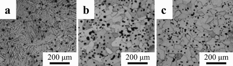
Ti alloys have been reported to be susceptible to interstitial contamination from volatiles produced from the insulator/susceptor materials during microwave sintering [229]. However, the sample purity and mechanical properties can be improved by using Ti sponge as a getter to protect the samples during microwave sintering [218]. By using Ti sponge to protect the samples, CP-Ti was produced with tensile properties that fall within the range of the ASTM B348 standard [232] for Grade 2 and Grade 4 CP-Ti. Ti–6Al–4V was produced with the ultimate tensile strength (UTS) of approximately 970 MPa and approximately 7.5%EL, which are below the ASTM B348 standard for Grade 5 Ti–6Al–4V. However, better mechanical properties were reported in this study for microwave-sintered Ti–10V–2Fe–3Al (980 MPa UTS and 17.6%EL for the most ductile sample).
Spark plasma sintering
Spark plasma sintering (SPS), which is also known as the field-assisted sintering technique, plasma-activated sintering, pulsed electric current sintering, or plasma-pressure-compaction, is a sintering technology that utilises Joule heating via a pulsed electric current to achieve densification. Similar to VHP and HIP, SPS uses simultaneous heating and pressure to facilitate improved consolidation. Additionally, it has been theorised that the Joule heating could lead to further improved densification via localised plastic flow at the necks of connected particles during sintering [233,234].
It has been reported that essentially full density CP-Ti can be achieved from 45 μm HDH powder at approximately 750°C using a 50°C min−1 heating rate and 100 MPa of applied pressure [235]. The mechanical properties that can be achieved using SPS of CP-Ti powders are also very promising. One study reported the ability to produce nanostructured Grade 2 CP-Ti with 840 MPa tensile strength and 27%EL via SPS of cryogenically milled CP-Ti powder [236]. These mechanical properties far exceed those designated for wrought CP-Ti [232].
Figure 24(a) shows the microstructures of Ti–6Al–4V produced via SPS of a powder blend (i.e. BE powder) of HDH Ti (48–75 μm) and 60Al–40V master-alloy [237]. This sample was sintered via SPS at 900°C for 5 min with a heating rate of 20°C min−1 under 30 MPa of pressure. At this time, temperature and pressure, appreciable densification is achieved. However, this sample had an inhomogeneous microstructure [237]. Figure 24(b) shows the same blended powder sintered at 1100°C for 15 min with the same heating rate and applied pressure. For comparison, a sample prepared with the same SPS parameters, but from PA Ti–6Al–4V powder, is shown in Figure 24(c) [237]. All three samples exhibited appreciable densification. However, when a sintering temperature below the β-transus is used, regardless of whether BE or PA powder is used, an inhomogeneous microstructure is produced. This is indicative of insufficient diffusion of the alloying elements during sintering at lower temperatures. SEM micrographs of Ti–6Al–4V produced via SPS: (a) blended master alloy powder at 900°C for 5 min, (b) blended master alloy powder at 1100°C for 15 min, and (c) PA powder at 1100°C for 15 min [237]. (Reproduced with permission.)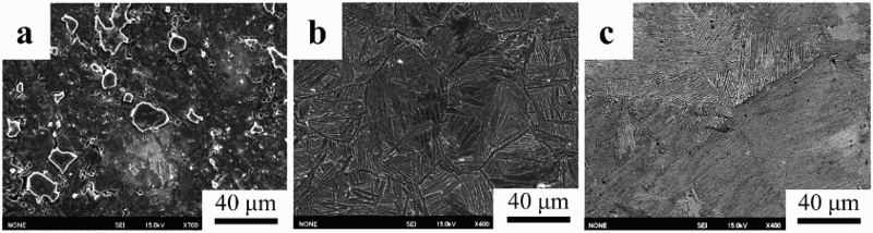
From current literature, SPS appears to be promising for CP-Ti. However, high temperatures are still required to produce a homogeneous microstructure in Ti alloys due to the necessity for diffusion of the alloying elements. Therefore, this process will normally result in the same relatively coarse lamellar microstructure observed from traditional sintering of Ti–6Al–4V. However, it is important to note that the temperature required for sufficient diffusion of alloying elements during SPS is apparently lower than that required for other pressure-assisted sintering technologies, such as VHP. It has been theorised that the Joule heating caused by SPS may have some beneficial effect on the diffusion of alloying elements during Ti–6Al–4V sintering from blended powders [238].
Powder rolling
Certain geometries, such as sheet, strip, and plate, are not suitable for production via traditional powder metallurgy consolidation techniques. Therefore, the process of powder rolling has been developed to address this limitation. This process has been studied for several alloy systems, including Ti, since 1950 [239]. As such, the ASM handbook on powder metallurgy has a section dedicated to powder compaction by rolling [240]. DuPont developed a commercial process for producing Ti strip via powder rolling in the 1960s [141]. However, despite exhibiting promising mechanical properties, the DuPont strip Ti exhibited poor weldability due to chloride impurities in the final product.
In one study, a green part was produced by direct powder rolling low-cost elemental Ti powder followed by vacuum sintering [241]. In this study, green CP-Ti strips measuring up to 1.5 mm thick and up to 300 mm wide were produced by direct powder rolling. The green parts were sintered under vacuum at 1000–1250°C for 1–4 h. After sintering, the strips were rolled again and annealed to produce Ti sheet measuring approximately 0.5 mm in thickness. Promising mechanical properties were reported, which were dependent primarily on the annealing treatment used after sintering.
Another process has been under recent development by CSIRO in Australia for the production of thin gauge Ti alloy sheets from PA or BE powders [242–245]. The CSIRO process utilises several steps to produce fully dense Ti alloy sheets. These steps include direct powder rolling, heating under inert gas for hot rolling, mill annealing, final cold rolling, and annealing (Figure 25) [245]. After annealing, the strips are generally treated to remove a thin layer (0.05 mm) from each surface. These steps can be accomplished in a manner that allows for a continuous production process, if implemented commercially. Schematic diagram of CSIRO process for producing CP-Ti strip from metal powder [245]. (Reproduced with permission.)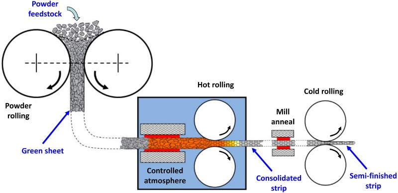
The microstructural evolution of CP-Ti during the CSIRO processes is shown in Figure 26. It has been reported that typical irregularly shaped HDH CP-Ti powder can be formed into CP-Ti sheet with mechanical properties approaching those available via WP and with similar purity (0.12 wt-% O, 0.013 wt-% N, and 10 ppm H) [245]. This particular study reported a UTS of 517–520 MPa and ductility of 20–27%EL, depending on the testing direction. Greater strength was exhibited when tested perpendicular to the rolling direction, while greater ductility was exhibited when tested parallel to the rolling direction. Microstructural evolution of CP-Ti during the CSIRO process (arrows indicate rolling direction): (a) HDH CP-Ti powder feedstock, (b) as direct powder rolled, (c) as hot-rolled, and (d) fully recrystallised structure after annealing [245]. (Reproduced with permission.)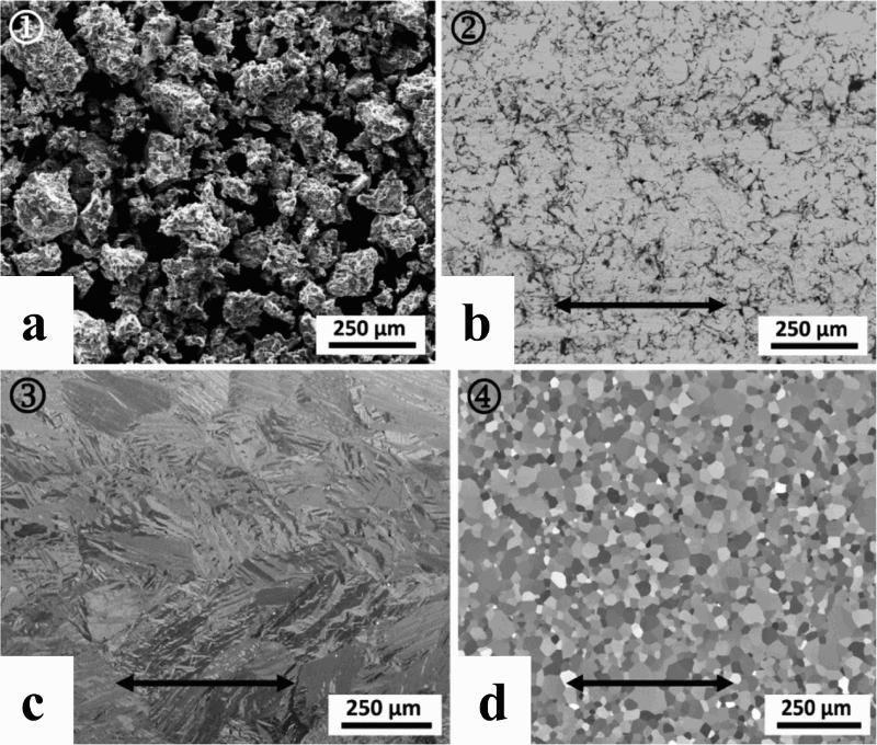
Forging
Forging has been used in PM Ti as a means to close porosity or refine the coarse microstructure through TMP. In fact, it has been traditionally thought that achieving superior mechanical properties of PM Ti alloys would require some form of TMP to be competitive with wrought [246]. During powder forging, a green preform is prepared via die pressing or CIP. The preform may be forged directly, or first sintered prior to die forging. Ideally, the preform will have a geometry that is conducive to producing the desired final net shape after forging. The forging step serves to close residual porosity and refine the microstructure. Forging of PM components has been shown to significantly improve the mechanical properties of PM parts, particularly the fatigue performance. Therefore, this process is currently used commercially for the production of high-strength iron alloy parts for drive train components (e.g. connecting rods) for automobiles. This process has also been investigated for the production of Ti alloy connecting rods [247]. Additionally, powder forging has been patented by Toyota for the production of Ti metal matrix composite engine valves [142,248,249]. Another study has investigated the process of producing billets for extrusion from TiH2 powder via vacuum sintering [250].
Zhang et al. investigated the ability to produce Ti–6Al–4V by preheating a green part of BE or PA powder to 1200°C and immediately forging. While the microstructure produced by this method was much finer than that typical of traditional sintering, the forgings exhibited cracking, especially at the edges, which appeared to negatively impact ductility. However, two other studies used traditional sintering to produce the preform, followed by forging and heat treatment with better results [247,251]. Figure 27 shows the microstructure of a PM connecting rod of Ti–1.5Fe–2.25Mo that was first sintered at 1300°C before forging and heat treatment. As seen, the as-sintered sample has the coarse lamellar microstructure that is typical of PM α + β Ti alloys (Figure 27(a)). However, after forging, the microstructure is significantly refined in all areas of the connecting rod (Figure 27(b)), with the finest microstructure found in the shank (Figure 27(c)) [247]. Similar results were observed in a study on PM Ti–10V–2Fe–3V sintered at 1200°C followed by forging and heat treatment [251]. Microstructures of Ti–1.5Fe–2.25Mo connecting rod produced by powder forging: (a) OM of as-sintered material, (b) SEM of forged and heat-treated fork, and (c) SEM of forged and heat-treated shank [247]. (Reproduced with permission.)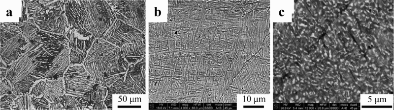
Gaseous isostatic forging
Gaseous isostatic forging (GIF) technology, also known as pneumatic isostatic forging (PIF), is a post-sintering process to increase the density of a sintered article [252–255]. GIF is similar to HIP, in that it uses isostatic pressure at elevated temperatures to close pores. However, unlike HIP, GIF utilises a separate furnace to heat the samples before pressurisation [256]. The fact that the pressure chamber is not heated during GIF allows for maximum pressures above 400 MPa, which are significantly higher than what is typically possible with HIP. Furthermore, because the heating and pressurisation are separate processes, the apparatuses used for this process are also much less complicated and do not require expensive materials and designs capable of handling high pressure at elevated temperatures. Additionally, the use of a separate furnace means the samples can be heated rapidly and then quickly pressurised and depressurised, allowing for much faster production rates. This also means that the processed part is at high temperature for only a short time. Therefore, as the name suggests, this process is much more like a forging process, though it is isostatic and is, therefore, better suited for processing of near-net-shape PM parts with complex geometries. This process was first patented in 1998 [257] and has been commercialised to close porosity in parts produced by casting [258] or PM processing [257].
As reported in the literature [257], Ti alloys are typically heated to a temperature between 845 and 900°C during GIF. After heating, the material is loaded into the pressure vessel. Typically, a maximum pressure between 300 and 415 MPa can be achieved with a pressurisation rate as fast as 28 MPa s−1. The initial rapid pressurisation has been called an ‘air hammer’, which is achieved by opening a valve between the pressure chamber and a pre-pressurised gas reservoir. Super-transus (>1000°C) GIF treatments of Ti–6Al–4V have also been reported [252]. A simple schematic showing the primary steps of the GIF process is shown in Figure 28. Schematic representation of a GIF process.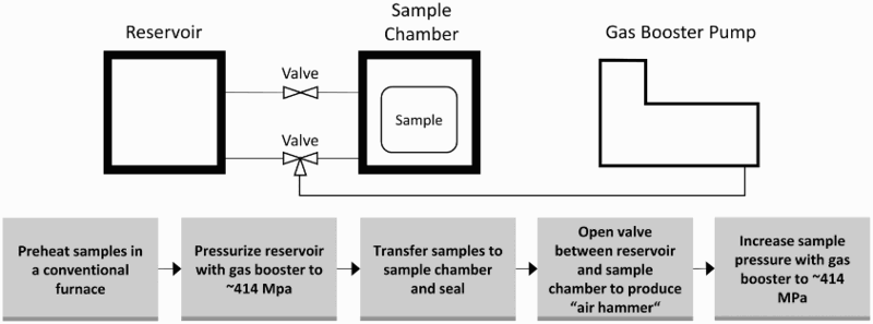
The primary advantage of GIF in PM processing is to close the porosity of the as-sintered material in a truly low-cost and near-net-shape compatible method that is capable of high production rates. Owing to its isostatic nature, GIF does not produce shear, meaning it is not capable of refining the microstructure due to recrystallisation. Figure 29 shows the microstructures of PM Ti–6Al–4V that have been traditionally β-forged (Figure 29(a)) versus GIF (Figure 29(b)) [252]. As shown, the GIF microstructure is unchanged by this process and has the as-sintered coarse lamellar microstructure that is typical of PM Ti–6Al–4V. On the other hand, the traditionally β-forged microstructure is significantly finer than the GIF microstructure, as dynamic recrystallisation during hot working above the β-transus temperature refines the microstructure. Microstructure of PM Ti–6Al–4V after post-sintering forging treatments: (a) traditional β-forging, and (b) pneumatic isostatic forging (PIF/GIF) [252]. (Reproduced with permission.)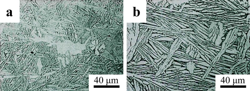
Special forming and consolidation technologies
In addition to traditional powder metallurgy methods, PM Ti can be manufactured by special forming and consolidation technologies. Two important near-net-shape technologies, MIM and AM, are briefly reviewed with respect to Ti manufacturing in the following sections.
MIM of Ti
During MIM, a binder consisting of waxes and thermoplastics is mixed with metal powder and formed in a process similar to that used in the plastics industry. The binder must produce sufficient flowability of the mixture at the injection temperature, as well as produce sufficient green strength upon cooling. The MIM process consists of the following steps: preparing feedstock, injection molding, de-binding (solvent and thermal), and sintering. Compared to conventional PM methods, the MIM technology has advantages for mass production of parts with complex shapes and relatively small size, but it has dimensional limitations as well as a risk of contamination and distortion due to the adding and the removal of a large amount of binder. The application of the MIM method to Ti was first reported by Kaneko et al. in Japan in the late 1980s and early 1990s [259–261]. As a result of consistent development for more than two decades, many Ti components produced via MIM are commercially available today. Additionally, several comprehensive review papers and book chapters have been published on MIM of Ti in the past decade [262–266].
As with other PM processes, the three critical factors which determine the mechanical properties of MIM parts are interstitial impurity concentrations, sintered density, and microstructure. A higher density can be obtained when finer Ti powder is used. On the other hand, finer powders face a higher risk of contamination, especially by oxygen and nitrogen, during handling and sintering due to a larger specific surface area. Therefore, <44 μm (−325 mesh) spherical Ti powder is usually considered an acceptable compromise with regard to sintered density and interstitial concentrations [187,265]. As discussed in section ‘Atomization’, spherical Ti powder produced by GA or PREP methods is expensive. This consideration has motivated research into the viability of using less expensive raw materials, such as HDH Ti [267–270] or TiH2 [177,191,260,267,271–273]. The irregular particle shape of HDH Ti or TiH2 powder generally results in poor flowability of the powder/binder mixture during injection molding. However, it has been proposed that mixing HDH powder with atomised powder could be an effective approach to balance the cost and rheological factors [266,274].
The pickup of interstitial elements is inevitable to some degree during any MIM process. Typically, oxygen pickup is about 0.08 wt-% during MIM of Ti, but it can be reduced to 0.03–0.05 wt-% by minimising oxygen exposure of the powder during all production steps [265]. Therefore, the oxygen content of the starting powder must be sufficiently low to account for this pickup and meet the desired purity of the final parts [232]. Another important challenge for MIM of Ti is controlling the carbon contamination from the binders. Typically, the carbon pickup can be controlled to less than 0.05 wt-% during the entire MIM process [266]. Therefore, Ti carbide is typically absent from Ti–6Al–4V and CP-Ti produced via MIM, as long as the final carbon concentration is kept below 0.08 wt-%. However, the carbon concentration is of particular importance for β-Ti alloys. For example, as the concentration of molybdenum (a common β stabiliser) is increased from 0 to 15 wt-%, the solubility of carbon decreases from 800 ppm (0.08 wt-%) to 60 ppm [275,276]. Therefore, the formation of Ti carbide has been observed by Zhao et al. [277,278] and Yan et al. [275] in β alloys with trace carbon concentrations produced via MIM.
The as-sintered density of MIM Ti–6Al–4V is generally in the range of 96–97%TD with reasonable purity. However, higher relative densities (>98%) can be achieved by using finer powder, though doing so compromises purity [265]. HIP is an effective way to close residual porosity after MIM and thus improve both tensile and fatigue properties. However, as mentioned previously, doing so increases the cost of the final product. Conversely, GIF, as discussed in section ‘Gaseous isostatic forging’, may be a low-cost alternative to HIP for increasing the density of MIM Ti alloys. Additionally, shot peening has been reported as an economic way to improve the mechanical performance of MIM Ti parts by eliminating the sites of surface crack initiation [279,280].
The main alloys for MIM Ti parts are CP-Ti and Ti–6Al–4V. However, research has increasingly been reported on MIM of β-Ti alloys for potential medical applications [275,281–284]. MIM has also been investigated for producing Ti aluminides for high-temperature application, [285–290]. Additionally, the possibility of using MIM with particulate space holders as a means to produce porous Ti implants has been explored in recent years [291–293].
AM of Ti
AM, or 3D printing, is ideal for low-volume production of complicated components [294]. Therefore, this technology is very well suited for many complicated and low-volume Ti components [295]. The topic is discussed briefly in this paper, as it holds unique promise for PM Ti. However, the reader is referred to the references cited in this section for detailed discussions on this topic.
AM of metals most commonly utilises selective sintering/melting via a laser or electron beam to build each part layer, either via a powder bed (powder bed fusion) that is replenished between layers or direct feeding of metal to the heat source (directed energy deposition) [295]. Another technology, called binder jetting, uses an inkjet print head to deposit binder on a powder bed in consecutive layers to produce a green part [296]. This technology requires subsequent debinding and sintering. However, using AM to produce a green part can take advantage of microstructural evolution during sintering, can use powders that are difficult to selectively sinter, and produce truly isotropic properties, which is difficult with selective sintering due to the complex thermal histories of each layer.
Owing to the promise of AM for small-volume production, significant research focus and attention has already been given to AM Ti–6Al–4V. In fact, an Aerospace Materials Specification for AM Ti–6Al–4V has been released for direct metal deposition of Ti–6Al–4V [297]. This specification requires an UTS for AM Ti–6Al–4V of 889 MPa and a ductility of 6%EL, taking into account the anisotropic properties. Despite being anisotropic, the currently reported mechanical properties of direct metal deposition of Ti–6Al–4V and other AM processes are generally promising. Post-processing such as HIP is required for most AM processes to produce Ti–6Al–4V with ductility beyond 10%EL. However, the reported tensile strengths in the as-printed Ti–6Al–4V range from just over 1000 MPa to just over 1200 MPa, with slight decreases in strength after HIP [295,298–300].
On a per-pound basis, AM is relatively expensive. However, this cost is easily offset by the ability to rapidly prototype unique parts, thereby eliminating setup and tooling costs, and the ability to produce near-net-shape products. For AM, spherical PA powders are typically preferred for their improved flowability. However, recent work has demonstrated the ability of AM to be used with lower-cost powders in some instances [301,302].
Mechanical properties of PM Ti
As discussed in section ‘Introduction’, PM Ti processing generally uses either BE or PA powder. As will be shown, PA tends to produce significantly improved mechanical properties compared to the BE method. However, PA powders tend to be expensive and require high-pressure consolidation processes. As discussed in section ‘Sintering of TiH2’, significant breakthroughs have been achieved using TiH2 in place of Ti powder in BE processing. Therefore, the mechanical properties that have resulted from these innovations will be discussed separately from the approaches using traditional Ti powder.
In this section, the mechanical properties will be discussed in relation to porosity, purity, and microstructure of the sintered alloys. Additionally, this section will focus primarily on the mechanical properties of Ti–6Al–4V, which can be engineered to have a wide range of properties. Therefore, this alloy is ideal for critically reviewing how processing affects the mechanical properties of PM Ti. Finally, the following discussion on the mechanical properties of PM Ti is divided into two sub topics: static tensile properties (section ‘Static properties’) and fatigue properties (section ‘Fatigue properties’).
Static properties
WP is able to produce Ti–6Al–4V with a wide range of tensile strengths and ductility, owing to the range of microstructures that are possible via TMP and subsequent heat treatments. For example, quenching Ti–6Al–4V from the β phase field will produce a martensitic microstructure with very high strength and limited ductility [303], while producing a microstructure with coarse α grains will produce increased ductility at the expense of tensile strength [304]. Additionally, interstitials such as oxygen can significantly strengthen the alloy, though an excess will compromise ductility [134,150,305]. By the ASTM B348 standard, the acceptable oxygen content for wrought Ti–6Al–4V is below 0.2 wt.% [232]. However, recent work has determined that higher levels may be acceptable with respect to ductility of PM Ti alloys (see section ‘Static properties of PM Ti–6Al–4V using BE powders’).
The mechanical properties of PM Ti–6Al–4V, as reported in the literature, are summarised in the property maps given in Figure 30 and compared with literature-reported values for wrought Ti–6Al–4V [3,129,137,138,154,157,160,161,174,175,192,193,204, 207,212,303–343]. The type of powder used, the sintering process, and any post-processing will affect the resulting mechanical properties. Therefore, the property maps have been broken into three different figures, representing the mechanical properties reported when BE Ti powder, PA Ti powder, and BE TiH2 powder are used. Additionally, each property map shows several fields, corresponding to the type of sintering used with each type of powder and whether or not post-processing was used, such as HIP, TMP, and/or heat treatments. The effect of the feedstock and processing on the density, purity, and microstructure and the resulting tensile properties will be discussed in the following sections. While this review will provide a concise overview of the tensile properties reported for PM Ti–6Al–4V, the authors refer the reader to a comprehensive review recently published by Kumar and Chandran [344] for a more detailed discussion on this particular topic. Mechanical property maps showing fields for the various PM processing routes versus WP: (a) using BE Ti powder with conventional sintering in the as-sintered state versus with subsequent post-processing (PP), (b) using PA Ti powder with pressure-assisted sintering in the as-sintered state versus with subsequent post-processing, (c) using BE TiH2 powder with vacuum sintering versus H2 sintering (section ‘Sintering of TiH2’) as well as H2 sintering with subsequent post-processing [3,129,137,138,154,157,160,161,174,175,192,193,204,207,212,303–343].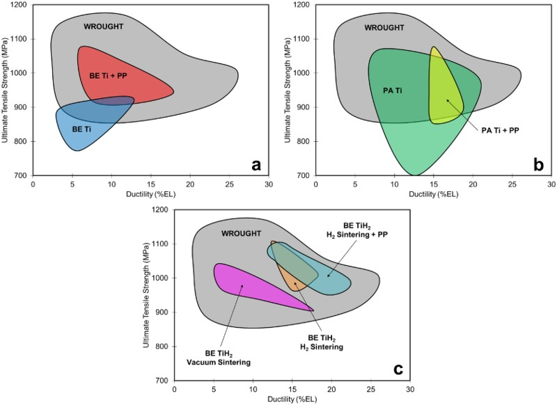
Static properties of PM Ti–6Al–4V using BE powders
Conventional cold compaction pressureless sintering of PM Ti–6Al–4V produced from BE Ti powder tends produce samples with relatively high amount of porosity, compared with the other processing routes discussed in this section. Both the tensile strength and ductility are strongly dependent on the density of the material. Therefore, as shown in Figure 30(a), PM Ti–6Al–4V produced from BE Ti powder has the poorest mechanical properties, particularly when no additional processing is utilised to increase the density of the alloy. In fact, much of the data reported for this process fails the ASTM B348 standard for Grade 5 titanium produced via WP (895 MPa UTS and 10%EL) [232]. Kumar and Chandran found that when comparing reported densities to tensile properties, there was more scatter among samples with higher relative density [344]. They attributed this finding to the occurrence of large rouge pores in the microstructure of some samples despite the relatively high density.
Applying pressure-assisted compaction such as HIP after sintering (e.g. the CHIP process discussed in section ‘CIP-sinter-HIP process’) has been reported to increase the as-sintered density from 98 to 100% TD, with a corresponding slight increase in ductility from 15 to 16%EL and a 13–14 MPa increase in strength [158]. Additionally, studies have reported success in increasing the sintered density of PM Ti–6Al–4V by cold working the BE powder compacts before sintering [308,317]. However, due to the deformation of the green part, such a process would not be feasible for near-net-shape production of complex geometries, so the applicability of such a process for PM is limited.
Chlorine content also has important implications for the tensile properties of BE Ti–6Al–4V. As opposed to oxygen, chlorine, which is often leftover in sponge as chlorides from the Kroll or Hunter process, has no documented positive effects on the tensile properties of PM Ti–6Al–4V and can have a deleterious effect on densification [128]. In fact, one paper reported a maximum as-sintered density of 95% TD when using sponge fines, which resulted in ductility of only 6%EL [310]. Conversely, in a later study, 98% TD was reported in the as-sintered state using extra low chlorine Ti powder produced by the HDH process, which resulted in an increase in ductility to 13%EL [314].
By the ASTM B348 standard, oxygen is typically limited to 0.2 wt-% in wrought alloys to avoid loss in ductility [232]. However, as shown in Figure 31, recent studies have determined that oxygen actually has a negligible effect on the ductility of PM Ti–6Al–4V up to about 0.33 wt-% [345–348], which is a 65% increase over the traditionally accepted limit. Beyond the critical oxygen level of 0.33 wt-%, a sharp decrease in tensile ductility is observed with increased oxygen content. The data in these papers were generated from powder injection molding studies, though the consolidation method should be of little consequence. Oxygen is well-known to be an alloying element with strong solution strengthening behaviour of Ti alloys which is also reflected in the data shown in Figure 31. Furthermore, oxygen content is directly related to the particle size (i.e. surface area) of the feedstock powder [5], which, in turn, has a strong effect on the as-sintered density of PM Ti. That is, finer powders have greater specific surface area/energy, meaning densification occurs more readily. The general trend for the dependence of the as-sintered oxygen content and density of PM Ti–6Al–4V on the specific surface area (particle size) of the starting powder is highlighted in Figure 32 [151]. These particular data were generated by milling TiH2 in heptane for different lengths of time, blending with master alloy, and consolidating using cold compaction and pressureless sintering. However, the general trend between particle size, oxygen concentration, and densification is consistent with essentially all PM methods. With all of these considerations, the ability for PM Ti alloys to have higher oxygen concentrations (up to 0.33 versus 0.2 wt-%) without sacrificing ductility may create the possibility for greater solution strengthening and improved as-sintered density and, therefore, ductility. As such, these findings have potentially significant implications for PM Ti alloys. Relationship between strength, ductility, and oxygen content of Ti–6Al–4V produced by MIM [346]. Effect of specific surface area (particle size) on the as-sintered oxygen content and density of Ti–6Al–4V produced from TiH2 powder after milling in heptane for different times [151].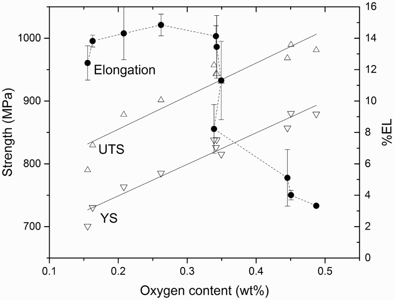
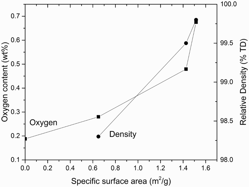
Owing to the strong strengthening behaviour of oxygen, intentionally introducing oxygen into PM Ti alloys has been investigated as well [349–351]. Sun et al. [351] reported that by allowing CP-Ti powder to pick up oxygen during warm compaction, elevated oxygen levels could be achieved that produced significantly improved tensile properties. It was reported that CP-Ti with 0.64 wt-% oxygen had a tensile strength of 974 MPa and ductility of 26%EL. However, all the samples tested in this study were extruded to a ratio of 37. Therefore, it is possible that the promising properties reported in this paper are reliant on post-sintering TMP. The same group has used a similar method to strengthen Ti–6Al–4V with oxygen for aerospace and defense applications [350]. The elevated oxygen levels were produced by mixing Ti–6Al–4V and TiO2 powders, which were subsequently spark plasma sintered (see section ‘Spark plasma sintering’) and then extruded to form the test material. The results obtained from oxygen strengthened Ti–6Al–4V were less impressive than CP-Ti. The strongest sample had a UTS of 1286 versus 1101 MPa for standard Ti–6Al–4V sample (17% increase), while the same two samples had a decrease in ductility from 21.2%EL for the standard sample to 8.5%EL for the high oxygen sample (60% decrease). One sample in the study exhibited a slight increase in both strength and ductility, though the remaining samples had a loss in ductility that was consistently more dramatic than the increase in strength.
Because of the effects that excessive oxygen or chlorine can have deleterious effects on mechanical properties, several studies have endeavored to utilise oxygen and chlorine scavenging alloying elements to improve tensile properties. In these studies, rare earth compounds, such as yttrium hydride (YH2) [352,353], lanthanum hydride (LaH2) [352], and lanthanum boride (LaB6) [342], have been added to Ti alloy powder compacts. It has been reported that these additions can successfully getter oxygen and chlorine, with a corresponding increase in tensile ductility. However, excessive additions can also lead to a decrease in tensile properties beyond a critical concentration of the gettering element. It has also been reported that, under certain circumstances, less expensive alloying elements may have beneficial effects on PM Ti alloys [354]. For example, Yan et al. [355] postulated that the reaction kinetics between Ti and Fe are accelerated when TiH2 powder is used as the feedstock in a PM process. Therefore, it was proposed that this phenomenon could enable the use of Fe to scavenge oxygen in PM Ti alloys via the formation of submicron Ti4Fe2O particles.
The microstructure of BE Ti–6Al–4V is typically a coarse lamellar structure, which results from super-transus sintering. This microstructure limits the mechanical properties that are possible, though the effect is greater on fatigue performance than static properties. However, because of this, even when post treatments are used to close porosity and the purity is effectively controlled, Ti–6Al–4V produced from BE Ti still has a limited range for tensile properties if the microstructure is unchanged. The as-sintered microstructure may be refined via TMP, which breaks up the coarse structure and drives the formation of a finer and more equiaxed grains through recrystallisation. Additionally, TMP will effectively increase the density of the material, which also positively affects tensile properties. However, TMP is energy-intensive and incompatible with near-net-shape manufacturing, which drives up the cost of the final product and is generally unsuitable for PM processing.
In short, for BE Ti–6Al–4V, the clearest trend among the available data for static properties is the effect of porosity on tensile ductility. The effect of purity is also important, as oxygen can act as a strong solution strengthener, though it is shown to compromise ductility beyond a critical level. The as-sintered microstructure of BE Ti–6Al–4V, in terms of grain size and morphology, cannot be controlled with traditional sintering processes. Therefore, this parameter cannot be readily optimised with respect to mechanical properties without incorporating costly post-sintering processing.
Static properties of PM Ti–6Al–4V using PA powders
Similar to BE processed Ti–6Al–4V, the strength and ductility of Ti–6Al–4V produced from PA powders will suffer if the relative density is below 99% [330]. As discussed in section ‘Pressure-assisted consolidation’, PA powders require some form of pressure-assisted sintering such as HIP or VHP to produce reasonable densities. These processes are generally conducted at pressures beyond the flow stress of Ti–6Al–4V. As such, porosity tends to be less of an issue with PA Ti–6Al–4V versus BE processing. In general, PA processing can produce better tensile properties than BE processing. However, as shown in Figure 30(b), there is a wide range of tensile properties reported for Ti–6Al–4V produced from PA powder. For example, ductility as low as 7.5%EL has been reported for fully dense PA Ti–6Al–4V [356]. One possible cause for relatively poor properties in PA Ti–6Al–4V despite full density is incomplete diffusion bonding across closed pores [344], which would be due to insufficient temperature or time during the consolidation process. Of course, purity and microstructure play important roles in the tensile properties of these alloys as well, which is discussed below.
Owing to their high cost and the nature of processing required to produce PA powders, oxygen and other interstitial element contents are generally optimised for PA powders. Therefore, this parameter tends not to play a significant role among the static properties of PA Ti–6Al–4V as reported in the literature.
Microstructure is an important controlling feature in fully-dense PA Ti–6Al–4V samples. As discussed in section ‘Pressure-assisted consolidation’ the microstructure of PA Ti alloys is largely controlled by the processing parameters used during consolidation (e.g. temperature). Therefore, PA processing allows for the production of a range of microstructures and corresponding mechanical properties. If a temperature beyond the β-transus is used during the consolidation process, a coarse lamellar microstructure and the corresponding mechanical properties will be produced. Therefore, if a finer and more equiaxed microstructure is desired, it is necessary to optimise the process to use a temperature below the β-transus while still producing a fully density and full bonded product.
As is evident in Figure 30(b), post-processing such as TMP and heat treatment does not significantly alter the strength and ductility available with PM Ti–6Al–4V produced from PA powders. It was pointed out in section ‘Hot isostatic pressing’ that 100% TD and a range of microstructures can be achieved in as-HIPed PA Ti–6Al–4V alloy. Therefore, if the primary consolidation process is optimised appropriately, additional processing steps will have a marginal effect on tensile strength and ductility combination. However, secondary processing steps have been used to enhance the fatigue properties of these alloys (section ‘Fatigue of PM Ti-6Al-4V alloys using PA powders’).
In summary, PA powders combined with pressure-assisted consolidation can produce superior tensile properties versus Ti–6Al–4V produced from BE Ti powders. However, it is important to remember that PA powders are generally up to an order of magnitude more expensive than BE powders. Furthermore, the need for applied pressure during consolidation significantly complicates the sintering process and makes it more energy-intensive. As such, PA processing would be better suited to processing that is less restrictive with regard to cost and productivity.
Static properties of PM Ti–6Al–4V using BE TiH2 powders
As discussed in section ‘Sintering of TiH2’, both the density and purity of PM Ti–6Al–4V is improved when TiH2 powder is used in a BE process versus Ti powder. As would be expected and as shown in Figure 30(c), this translates to improved tensile properties as well. Vacuum sintering of BE powders using TiH2 has reported tensile strengths as high as 1050 MPa or ductility as high as 17%EL for lower strength samples [201,202,341,357]. It has been suggested that by optimising the variables, such as initial powder size, compaction pressure, and sintering temperature and time, the tensile properties can be further improved for vacuum sintering of PM Ti–6Al–4V produced using BE TiH2 powders [340].
Despite the improved density and purity, conventional vacuum sintering of BE TiH2 powders produces a coarse lamellar microstructure in the as-sintered state similar to BE Ti powders. However, it has been recently shown that an H2 sintering process called ‘hydrogen sintering and phase transformation’ (HSPT, see section ‘Sintering of TiH2 in H2’), produces an ultra-fine grain microstructure in the as-sintered state. The as-sintered microstructure may also be modified via simple heat treatments to produce a range of wrought-like microstructures via simple heat treatments. It should be noted that the heat treatments utilised in HSPT Ti–6Al–4V are performed without TMP. A low-cost high pressure process called GIF (see section ‘Gaseous isostatic forging’) has been used to successfully close the remaining ∼1 vol-% porosity that remains after the pressureless sintering process. As reported in the literature, the various microstructures that are possible with the HSPT process produce Ti–6Al–4V with tensile strengths in the range of 970–1100 MPa and ductility in the range of 13–22%EL (Figure 30(c)) [174,204,207,212,213,358,359]. Additionally, recent publications have reported globularised microstructures with tensile ductility exceeding 22%EL while maintaining strength level around 1000 MPa [174,213].
Using TiH2 instead of Ti in a BE process has several apparent advantages over other processing. These studies report tensile properties that are on par with wrought Ti–6Al–4V. However, they do not require expensive PA powder or pressure-assisted sintering. Additionally, when H2 sintering is used (i.e. HSPT), a range of wrought-like microstructures and application-tailored mechanical properties are possible without requiring TMP. This is an important capability, as the popularity of wrought Ti–6Al–4V is due largely to its ability to meet the specific property requirements of a wide range of applications. Therefore, it is possible that these processes could be developed into economical and truly near-net-shape compatible PM processes as a feasible alternative to WP for producing high-performance Ti alloys.
Fatigue properties
The relatively low fatigue strength of PM Ti parts is a key issue that hinders the adoption of PM Ti, especially for aerospace and automobile applications. Therefore, this section focuses on evaluating the fatigue performance of Ti–6Al–4V alloys made from different types of powders. The goal of the review is to illustrate the powder, processes, and microstructural improvements that are necessary to achieve high fatigue strength in PM Ti–6Al–4V alloys, comparable to that achieved via WP.
Fatigue of PM Ti–6Al–4V alloys using BE powders
A compilation of currently available fatigue data of Ti–6Al–4V alloys [306,314,316,360] made by cold pressing and vacuum sintering of BE powders is presented in Figure 33. The data on fatigue behaviour after some post-sintering treatments are also included for comparison. The processing conditions, microstructural features, and tensile properties of the PM materials from which the fatigue data in Figure 33 are generated are listed in Table 6. In this paper, the common convention is used, defining the fatigue endurance limit as the cyclic stress maximum at which a specimen survives 107 cycles. Note: VS: vacuum sintering; WQ: water quench.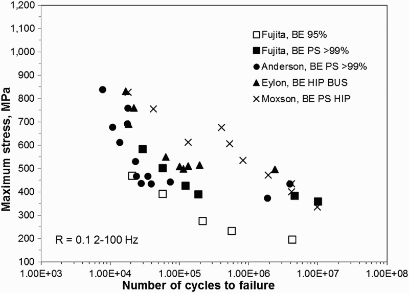
Examples of published processing conditions, microstructure, and tensile properties of PM Ti–6Al–4V alloys using BE powders.
Porosity has the most significant effect on fatigue performance. In PM Ti alloys with density <99% of the TD, the tensile and fatigue strength levels are lower [316,361] than acceptable, as mechanical properties strongly degrade when the levels of porosity increase. Therefore, the fatigue data presented in Figure 33 have been restricted to materials with density >99%TD. On this basis, it can be seen in Figure 33 that the fatigue strength levels for the BE method alloys have a range from 300 MPa to approximately 400 MPa.
HIP has proved to be an effective way to obtain components at or near 100% density. As seen in Figure 33, the lower-cycle fatigue strengths are improved when HIP is used to close porosity. However, the coarse lamellar microstructure in PM Ti–6Al–4V cannot be avoided in conventional BE sintering processes [313,360]. Thus, even if the porosity is eliminated by HIP or some other process, the coarse lamellar colonies initiate fatigue cracks with relative ease, leading to a generally poor high cycle fatigue strengths for BE Ti–6Al–4V.
The typical BE Ti–6Al–4V sintering process produces a coarse lamellar microstructure, which leads to early crack nucleation in fatigue, even when porosity is absent [148]. This type of microstructure also has the lowest fatigue strength level of all the microstructures possible in wrought and heat-treated Ti–6Al–4V. Chait and DeSisto [362] showed that the high cycle fatigue strength correlated well with the size of the α phase, more specifically with the width of α-platelets in the transformed β microstructure. Therefore, the fatigue strength of BE Ti–6Al–4V may be further improved by refining the microstructure, though this would typically require costly post-processing that is not near-net-shape compatible, such as TMP.
Eylon et al. [360] performed HIP and heat treatment on BE Ti–6Al–4V compact. However, the fatigue strength of these materials is much lower than that obtained by others using comparable processes. Although the volume fraction of porosity was low (>99.5%TD), it is possible that large rogue pores or other coarse microstructural features were responsible for the poor fatigue strength. Cao et al. have theorised that despite the overall density of the material [363,364], the fatigue strength of titanium alloys can be severely limited by the occurrence of a single pore in the microstructure. The size, geometry, and location of the pore are all reported to play significant roles in the resulting fatigue performance of the material. This is because these features determine under what loading the pore will initiate a fatigue crack, which will ultimately lead to the failure of the material.
Fatigue of PM Ti–6Al–4V alloys using PA powders
The use of PA powder to produce PM Ti parts can be quite effective, because of two advantages: (i) alloying of elements are accomplished in the liquid state before powder atomisation and (ii) improved densification by pressure-assisted consolidation techniques such as HIP. Direct consolidation by HIP at a temperature below or above β-transus has been used in industry to produce near fully dense PA Ti–6Al–4V. The fatigue data of Ti–6Al–4V alloys made from PA powders, as reported in past studies, are compiled in Figure 34 and Table 7 [154,343,360]. Porosity is less of a concern with PA Ti–6Al–4V, owing to the fact that consolidation must be performed via pressure-assisted consolidation techniques such as HIP, effectively producing densities close to 100%. Note: VA: vacuum atomisation; WQ: water quech; AC: air cool; De-H: hydrogenation.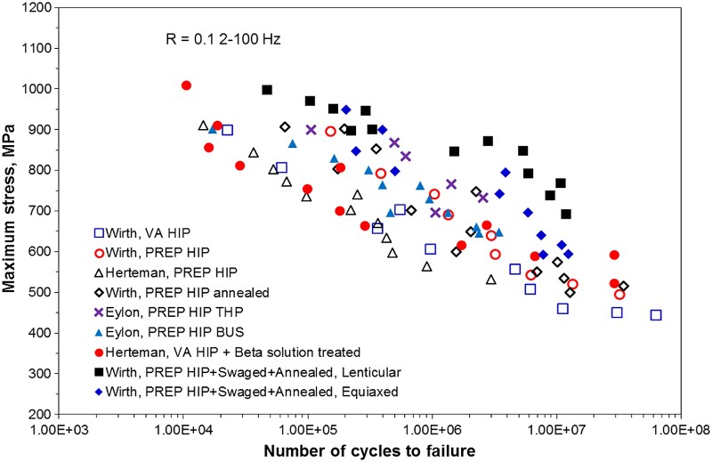
Examples of published processing conditions, microstructure, and tensile properties of PA Ti–6Al–4V alloys.
The microstructure of PA Ti–6Al–4V is invariably finer than that obtained from BE processing when the HIP temperature and time is well optimised [12,154]. Because of the improved density and finer microstructure, the fatigue strengths of as-sintered Ti–6Al–4V alloys made from PA powders consolidated using pressure-assisted sintering techniques, like HIP, are generally much higher than those of as-sintered samples obtained from BE powders. This can be understood by direct comparisons of data between Figures 33 and 34.
Heat treatments have also been attempted, in order to further improve the fatigue strength in PA Ti–6Al–4V. However, as shown in Figure 34, the improvement is not as significant as that seen in BE approaches. This is probably because the as-sintered properties of BE Ti–6Al–4V are lower than those of PA Ti–6Al–4V prior to heat treatment.
Thermomechanical processes such as isothermal forging, rolling, and swaging have been used with the intent of refining the microstructure [154,312], which could lead to further increases in the fatigue strength. Wirth et al. [154] used a swaging process on compacts obtained by HIP of PA powders, followed by two different heat treatment procedures to get PM Ti–6Al–4V alloys with equiaxed α and lenticular α microstructures (Table 7). This study produced Ti–6Al–4V with a 107 endurance limit of 750 MPa, which is the best reported for PM Ti–6Al–4V to date. Traditional ingot-melt Ti–6Al–4V samples were subjected to identical mechanical working and heat treatment, which produced nearly identical fatigue performance. Therefore, the performance of the PM Ti–6Al–4V was proposed to result from improved crack propagation resistance of the microstructure. This was attributed to the uniform precipitation of α phase inside the β grains as well as in the regions near to the prior β grain boundaries [154,365]. This data indicates that an effective method to produce wrought-like fatigue performance is to apply adequate cold working before HIP to induce uniform recrystallisation of the microstructure.
Fatigue of PM Ti–6Al–4V alloys using BE TiH2 powders
Examples of published processing conditions, microstructure, and tensile properties of BE Ti–6Al–4V using TiH2 powders.
Note: VS: vacuum sintering; De-H: dehydrogenation, HT: heat treatment, FC: furnace cool, WQ: water quench, AC: air cool.
As mentioned previously, the HSPT process produces Ti–6Al–4V with a significantly refined microstructure. Cao et al. [214] evaluated the fatigue performance of HSPT produced materials under different processing conditions, using cyclic axial fatigue testing, as defined by the ASTM standard [366]. Figure 35 shows that the 107 cycle fatigue strength of as-sintered HSPT Ti–6Al–4V is in the range between 450–500 MPa. The fatigue strength at 107 cycles increases to approximately 550 MPa after GIF is applied, which produces density >99.9%. Figure 35 illustrates that GIF greatly increases the fatigue strengths for cycles less than 5 million. As the endurance limit is approached, the S–N curves for the different conditions converge. It was proposed by Cao et al. that the rapid decline of fatigue strength near the endurance limit is due to the existence of grain boundary α along the prior β grain boundaries. However, it is evident that the HSPT Ti–6Al–4V fatigue strength is far superior to that of traditional BE Ti–6Al–4V and is competitive with wrought or PA Ti–6Al–4V when the GIF process is used, especially below 5 million cycles. Since the fatigue data for the vacuum-sintered Ti–6Al–4V reported by Ivasishin et al. [194] and Joshi et al. [341] were not measured using axial fatigue testing, it is not possible to make a valid comparison between the two types of BE processing of TiH2. S–N fatigue data of PM Ti–6Al–4V alloys made from BE TiH2 powders [214]. (HSPT: see section ‘Sintering of TiH2 in H2’, GIF: see section ‘Gaseous isostatic forging’.)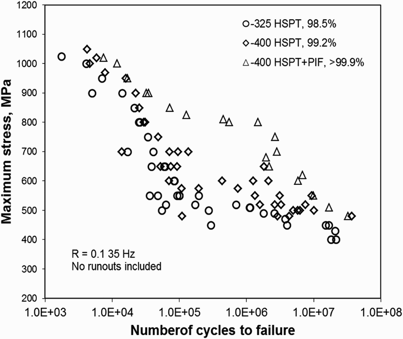
As mentioned in section ‘Sintering of TiH2 in H2’, the as-sintered ultrafine grain microstructure produced by the HSPT process may be further modified via simple heat treatments to produce globularised and bi-modal microstructures [208,213]. The samples with microstructures that result from these heat treatments were tested for fatigue performance by Paramore et al. [174,213]. Before heat treatment, the HSPT-produced samples were processed via GIF to close porosity (section ‘Gaseous isostatic forging’), as porosity would obscure the effect of the microstructure on fatigue performance. In these studies, it was found that the heat-treated microstructures increased fatigue strength compared with the as-sintered via HSPT and as-processed via GIF samples. As shown in Figure 36, the globularised microstructure has a 107 cycle fatigue strength of 575 MPa, while the bi-modal microstructure has a 107 cycle fatigue strength of 600 MPa. These data show that an endurance limit that is competitive with high-performance wrought Ti–6Al–4V can be achieved via truly low-cost and near-net-shape compatible BE powder metallurgy without requiring costly post-processing. S–N curves for Ti–6Al–4V produced via HSPT (see section ‘Sintering of TiH2 in H2’) followed by GIF (see section ‘Gaseous isostatic forging’) and heat treated to produce ‘globularized’ and bi-modal microstructures. S–N curves of vacuum sintered Ti–6Al–4V produced from identical powder with and without subsequent GIF processing is also shown as a comparison to the HSPT process. For reference, these data are overlaid on the fatigue life scatter-bands (prepared from data in the ASM Handbooks [11]) for Ti–6Al–4V produced via ingot metallurgy/WP with a mill-annealed microstructure, PA powder metallurgy, and BE/master-alloy powder metallurgy [213].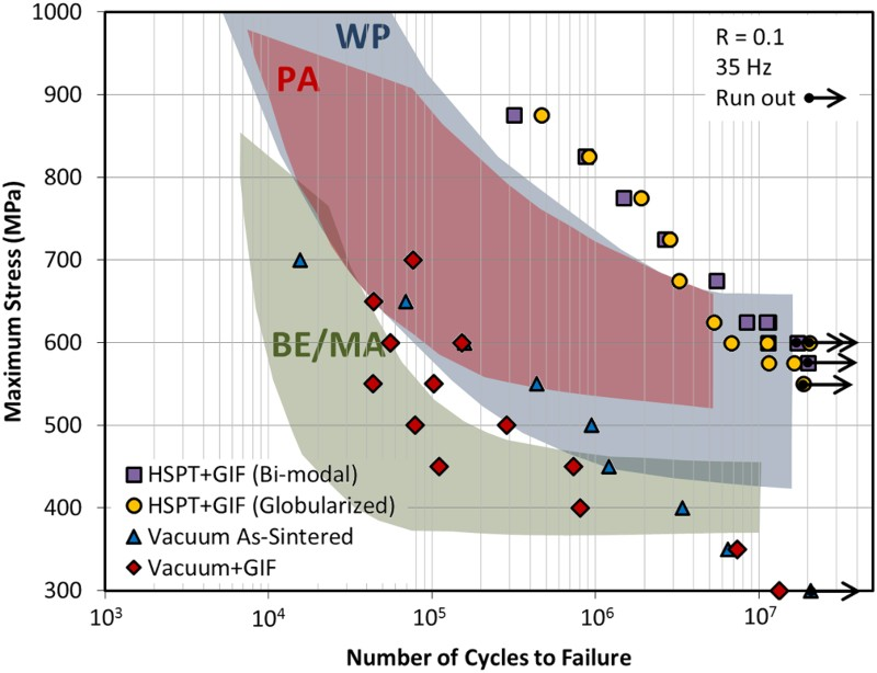
Summary
The review presented above shows that there are a large variety of techniques for making titanium powder, as well as for forming parts from these powders. Among the powder production processes, many are in various developmental stages. The motivation for developing new processes is often firmly rooted in the ambition of attaining a low-cost alternative to the Kroll process for Ti primary metal production. The status of the industry, including the research community, is that no technique is available to date for meeting both cost and quality goals matching those of the Kroll method. A number of developmental methods have garnered considerable interest and scale-up efforts, including the Armstrong process and the FFC Cambridge process. The Armstrong process is an example of using a continuous process for the reduction of TiCl4 using Na or Mg. Although continuous processing has the potential to lower the processing energy costs, the combined cost of the feedstock for reduction (TiCl4 or TiO2) and the reducing agent (Mg, Na, or Ca) plays an even more important role in determining the cost of Ti metal production. The FFC Cambridge process is an example of the various electrochemical methods that convert TiO2 to Ti metal in molten salt. The development of the FFC and other electrochemical methods is an ongoing effort. Challenges to improve energy efficiency and scale-up are yet to be overcome.
A recently developed method, i.e. the HAMR process, is based on the destabilisation of the Ti–O system using hydrogen as a temporary alloying element during the magnesiothermic reduction of TiO2. The published data of the chemical compositions, especially oxygen content, of the powders produced by the HAMR process indicates that it is a very promising method.
Titanium powders that are commercially available today are all made from titanium sponge, Ti ingot, Ti mill products, and/or Ti scrap metals. There are mainly two types: HDH powder and atomised powder. Atomisation is the process of choice when alloyed powders are required. However, atomised powders are considerably more costly than HDH powders, which is partially because the yield of particle sizes that are marketable is generally low. Despite these issues, atomising of Ti alloys has seen continued technology advancements with respect to increasing the yield of fine powders and minimising the contamination from nozzle materials by eliminating the need for nozzles. Owing to the advent of AM using metals, the development and utilisation of atomisation processes for making spherical Ti alloy powders have found a new and burgeoning frontier.
In terms of converting these powders into functional components, a long list of processes has been applied to the consolidation and sintering of Ti and Ti alloy powders, including both pressure-less and pressure-assisted sintering processes. Owing to the strict requirements for low oxygen, sintering under vacuum is the most popular process. Understandably, pressure-assisted techniques such as HIP yield both full density and good mechanical properties, although accompanied by relatively high cost. Regardless of which traditional sintering processes is used, as-sintered Ti–6Al–4V always has a coarse columnar microstructure because sintering is almost always carried out at a temperature above the β transus temperature. Although heat treatments can be applied, the microstructure and properties of conventionally sintered PM Ti cannot match those of wrought alloys because the TMP processes that wrought alloys are subjected to provide the driving force for microstructural augmentation. However, the recent development of the HSPT process in combination with the subsequent standard heat treatment has overcome that impasse, i.e. the PM Ti sintered via the HSPT process can be heat treated to yield microstructures that are equivalent to those of wrought alloys.
Technically, there are three key factors that affect the mechanical properties of PM Ti alloys: porosity, oxygen content, and microstructure. As discussed in section ‘Mechanical properties of PM Ti’, the alloy must have no less than 98% of TD to achieve generally acceptable static tensile properties. However, anything less than 99% will limit the fatigue performance. Furthermore, to achieve the fatigue strength of high-performance wrought Ti–6Al–4V (endurance limit >500 MPa) requires ∼100% density. When TiH2 is used as the raw material and dissolved hydrogen is present during β-phase sintering, >99%TD is possible via pressureless sintering. However, closing the remaining <1 vol.-% porosity requires some form of pressure-assisted consolidation. HIP is the traditional method to close the remaining porosity, though the GIF process appears to be a promising low-cost alternative.
It is important to note that the size of pores is critical to fatigue performance. Crack initiation often occurs at the edge of the largest pores present. The critical size of the pores that will dominate fatigue performance is dependent on the microstructure’s ability to resist crack propagation. Therefore, even in the presence of pores, fatigue limiting cracks can initiate by the fracturing of large α grains as well as trans-granular fracturing across entire α colonies, owing to the shared slip systems of the adjacent lamellar grains. As such, producing a fine microstructure is paramount for achieving high-performance fatigue strength. Furthermore, refining grain size has shown improved fatigue performance despite the presence of moderately sized pores. It has also been shown that PM Ti–6Al–4V processed using the HSPT technology has the potential to rival that of wrought Ti–6Al–4V by producing a fine wrought-like microstructure both in the as-sintered state and after heat treatment.
Controlling oxygen content is also a critical issue for PM Ti. Finer powders tend to produce better densification, but are also vulnerable to contamination due to increased surface area. Using hydrogenated Ti powder can improve the final purity, due to the decreased reactivity of the hydride. By the ASTM standard, 0.2 wt-% is the maximum allowed content for Grade 5 Ti–6Al–4V. However, recent work has indicated that oxygen plays a minimal role on tensile ductility up to 0.33 wt-%. There is no direct study to date on how the fatigue properties vary as a function of oxygen content, provided other microstructural features are identical.
The primary purpose of using PM processes, as opposed to traditional wrought processes, is to reduce the cost of manufacturing and, therefore, expand the use of Ti in industrial and consumer applications. However, the commercial applications of PM Ti are, incongruously, very limited to date because of high cost. The cost of PM Ti is often higher or equivalent to that of wrought Ti when it is held to the same performance standards, because additional high-cost processing steps and expensive feedstock are required to produce satisfactory microstructures and mechanical properties. In other words, the lack of an adequate performance-to-cost ratio is the main issue hindering the adoption of PM Ti in industry. In general, PM Ti made with the BE approach is truly low cost; however, it has unsatisfactory mechanical properties. Conversely, PM Ti made with the PA approach has adequate mechanical properties; however, it does not have significant cost advantages, if any, over wrought Ti alloys. A new process, namely the HSPT process, has shown the potential to maximise the performance-to-cost ratio by producing wrought-like Ti–6Al–4V using press-and-sinter and conventional heat treatment processes.
The goal of any PM Ti process is to produce Ti alloys with the mechanical properties necessary for critical applications while maintaining the low-cost benefit of PM. In order to remain truly low-cost, PM Ti must adhere to the following guidelines: Use low-cost powder as raw materials and employ a BE approach. Use low-cost compaction techniques to retain the ability to produce near-net-shape products. Use pressureless sintering techniques and avoid costly high-pressure consolidation processes. Obtain wrought-like microstructures through conventional heat treatment and avoid the need for TMP, which is not compatible with near-net-shape manufacturing and is inherently costly.
Finally, in short, titanium alloys made by using the conventional powder metallurgy approaches have not met the performance-to-cost ratios that are necessary for it to substitute for wrought titanium alloys, and thereby have widespread commercial success. The emerging technologies for making low-cost powders and the sintering processes to create wrought-like microstructure and mechanical properties without using wrought processes hold the promise to advance the PM of Ti to a new level. However, significant challenges remain for these emerging technologies to succeed, challenges which require integrated investments of effort in relation to end-use engineering, manufacturing, and materials science.