
Abstract
Although spinal manipulation is widely used in the management of neck and pain, its exact mechanisms and biomechancial effects are not clear. A porcine model was used to study the relative movements of intervertebral joints under spinal rotation maneuvers with different input angular displacements and thrust velocities. Ten porcine spines (C2/4) were fixed and mounted in a material testing machine. Rotational maneuvers with different input angular displacements (0.8, 1.5, 2 and 3°) and thrust velocities (0.1 – 200°/s) were applied to C2 with C4 fixed. Angular displacement induced at the adjacent level was measured and expressed as percentage of the applied angular displacement. For all the tested conditions, angular deformation at the adjacent level could not be avoided when an angular thrust was applied to the target level. The percentage of the angular displacement induced at the adjacent level was found to be dependent on both the input angular displacement and thrust velocity. If rapid thurst of manipulation is used to direct the input energy and motion at the target level with minimal interference at the adjacent levels, the applied angular displacement should not be too large and the thrust velocity should be within a medium velocity range.
Introduction
Manipulation has been widely employed since the time of Hippocrates (ca. 460 – 377 BC) known as the father of modern medicine. Even within a clinical context the word ‘manipulation’ is used broadly. For the purposes of this study, the use of the term manipulation refers specifically to the therapeutic technique of a high velocity, low amplitude thrust. Cervical spinal manipulation is most commonly applied for the treatment of neck problems of mechanical origin.1-8 Cassidy et al.2,9 studied the effect of rotational cervical manipulation on patients with unilateral neck pain without neurological deficit. The range of motion was found to increase in all planes after treatment.
The mechanism of manipulation is still poorly understood, and is still largely based on hypothetical arguments. Hessell et al.10 found that manipulation usually begins with a relatively constant pre-load force applied for several seconds. This pre-load force is used to displace the neutral zone before manipulation is applied until a peak force is reached.11,12 The thrust duration is the time from the sudden increase in force to the peak force, and the resolution phase is the decline of the force to zero. Herzog et al.13 showed that the cavitation effect occurred before the maximum thrust was reached and suggested that the thrust rate might be an important factor in joint cavitation. Gal et al.14 suggested that difference between the peak and pre-load force might be critical in achieving cavitation. Brodeur15 added that if the joint was loaded slowly, the ligaments would creep, and the energy within the capsule would be reduced, in turn decreasing the energy available for the elastic recoil.
Vicenzino et al.16 studied cervical motion during a cervical lateral glide treatment technique using a motion analysis system with reflective markers placed at the occiput, and the C5, T1, T3 and T5 vertebrae. Their results showed that linear displacement and peak velocity between C5 and T1 was greater than those between T1 and T3, occiput and C5, and T3 and T5. However, their technique under investigation was a gentle passive mobilization technique rather than a rapid, thrusting technique. McFadden and Taylor17 studied the gaping of the human lumbar facets under manual axial rotation, and suggested that it is not apparently possible to separate the articular surfaces. However, their input was a slow, sustained rotation rather than a rapid thrust. Gal et al.14 studied the movement of T10, T11 and T12 during spinal manipulative treatments to T12 using stainless-steel bone pins, high speed cinematography and cadaveric human subjects. They showed that there were significant relative movements between vertebrae. It was believed that this relative movement was due to the gaping of the facets. Ngan et al.18 studied the kinematics and intra- and inter-therapist consistencies of lower cervical manipulation. It was found that although consistent technique was used by different therapists, kinematic parameters were generally inconsistent between therapists.
The manipulation procedure is primarily a mechanical adjustment of the spinal anatomy, caused by a specific movement directed at a target level. Although the kinematic pattern in performing spinal manipulation was documented, the effect of the thrust velocity on the actual amount of movement induced to the respective functional spinal units (FSU) as well as the adjacent neighbouring FSU by spinal manipulation is still unknown. The aim of the study was to examine the kinematics of the spinal joint subject to a controlled rotation in vitro, and to examine the effect of range of rotational thrust and thrust velocity on target spinal level and the adjacent inferior level.
Yingling et al.19 studied the differences and similarities of the pig cervical spine and the human lumbar spine. They found that the structures of pig vertebrae are similar to the human, with the exception of the anterior processes which appear to have no significant mechanical role. The pars interarticularis was smaller in the pig vertebrae, but the pedicle compared well with human vertebrae. The facet joints of the human lumbar segment are oriented perpendicular to the vertebral body, which enables the facet joints to resist shear loading, and a similar alignment was found for the pig cervical vertebrae.20,21 Due to the similarities between human lumbar spine and porcine cervical spine, we adopted porcine cervical spine as a model in this study to investigate the effects of rotational manipulation on human lumbar spine.
Methods
Fresh adult porcine spines were obtained and stored frozen in sealed plastic bags at −20°C until testing. Specimens were allowed to thaw overnight at 4°C in a refrigerator before testing. Each specimen consisted of the three adjacent vertebrae from C2–C4 and the two intervertebral discs at C2/3 and C3/4. All paraspinal muscles were removed, preserving the bony tissues, spinal ligaments and other paravertebral soft tissues. In order to improve the fixation of the specimen, three bone screws were drilled into the vertebral bodies of C2 and C4 respectively. Metal wires were used to surround the three screws on each vertebra so that the contact surface between the specimen and mounting medium were increased. Once the specimen had been prepared, it was fixed in dental plaster so that it could be mounted to a biaxial material testing machine (MTS 858 mini-bionix servo-hydraulic material testing machine, MTS, Minneapolis, MN, USA).
The specimen was mounted with the C2 and C4 vertebrae secured to the upper and lower grips of the machine, respectively. Three markers were attached to the C3 vertebral body at the mid-height of C3, i.e., at the anterior border and the left and right lateral borders. These markers were used as visual guides to ensure that the longitudinal axis of C3 was aligned with the loading axis of the machine (Figure 1). Two rotary potentiometers were used to measure the relative angular displacement between C2 and C4, and between C3 and C4. One rotary potentiometer was linked fixed to the C2 and other potentiometer was linked and fixed to the C3 vertebral body by two light-weight aluminum rods. Both potentiometers were calibrated with root-mean-square (RMS) errors less than 0.1°. The angular displacement of C2/3 intervertebral joint was determined as the difference in angular displacement between C2/4 and C3/4 measured by the potentiometers.
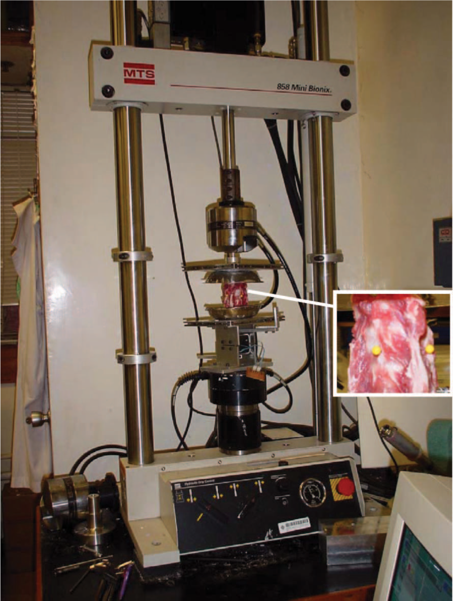
A specimen mounted in the biaxial materials testing machine. Three markers were attached to the C3 vertebral body at the mid-height of C3 as visual guides to ensure that the longitudinal axis of C3 was aligned with the loading axis of the machine.
Totally 10 porcine spine specimens were tested. Different angular displacements of 0.8°, 1.5°, 2° and 3° to the right (clockwise) were applied to C2 with C4 rigidly fixed to simulate different ranges of rotational thrust. For each input angular displacement, different angular velocities of 0.1°/s, 0.3°/s, 0.5°/s, 1°/s, 5°/s, 10°/s, 30°/s, 50°/s, 100°/s and 200°/s were used to simulate different rotational thrust velocities. These input ranges of angular displacement and thrust velocity were chosen based on a previous study of the kinematics of rotational manipulation applied to human subjects at C5/6 level.18
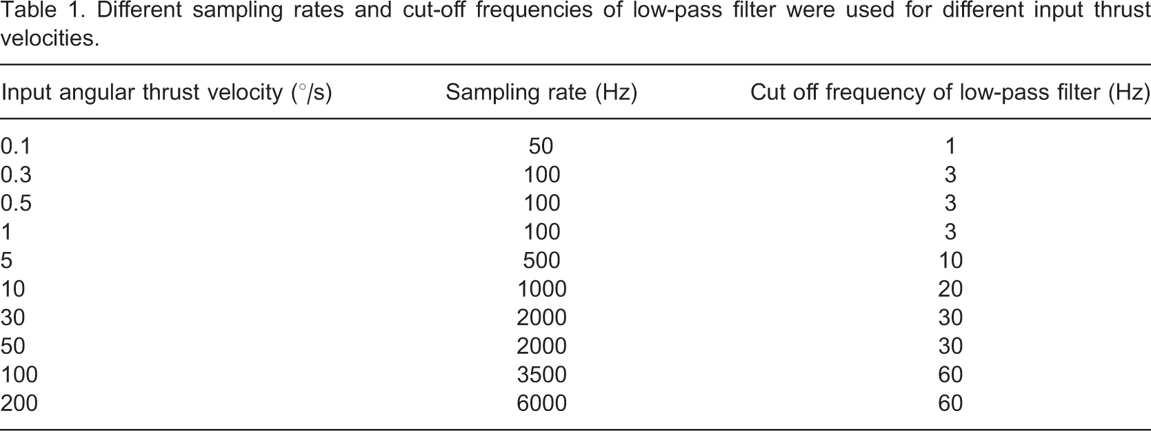
Different sampling rates and cut-off frequencies of low-pass filter were used for different input thrust velocities.
Results
A typical loading curve for a specimen rotated to 3° at velocity of 10°/s is shown in Figure 2. The angular displacements of C2/3 and C3/4 intervertebral joints both increased smoothly with the total angular displacement applied by the testing machine. To investigate the effects of input angular displacement and thrust velocity on the deformations of the target joint (i.e., C2/3) and the adjacent inferior joint (i.e., C3/4), the angular displacements at these two levels were expressed as percentage contribution to the total input angular displacement at the maximum input angular displacement (Figure 2). As the contributions of C2/3 and C3/4 to the total spinal deformation were complementary, only the percentage contribution of C3/4 (adjacent joint) to the total spinal deformation was analyzed (Figure 3). For all the tested conditions, it was shown that angular deformation at the adjacent inferior level (C3/4) could not be avoided when the angular thrust was applied to the target level (C2/3).
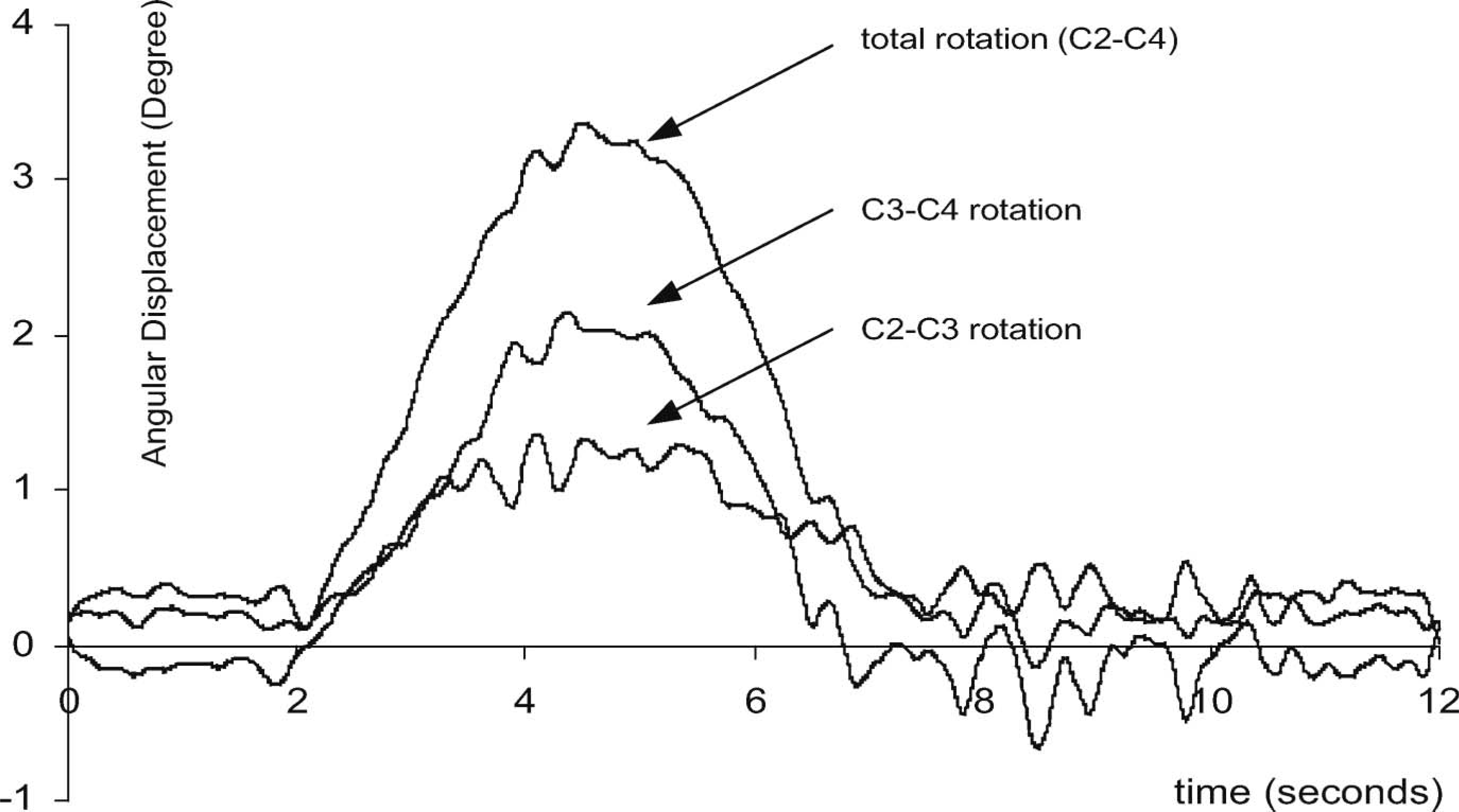
Relative angular displacements at C2/3 and C3/4 for a specimen rotated to 3° at an angular velocity of 10°/s.
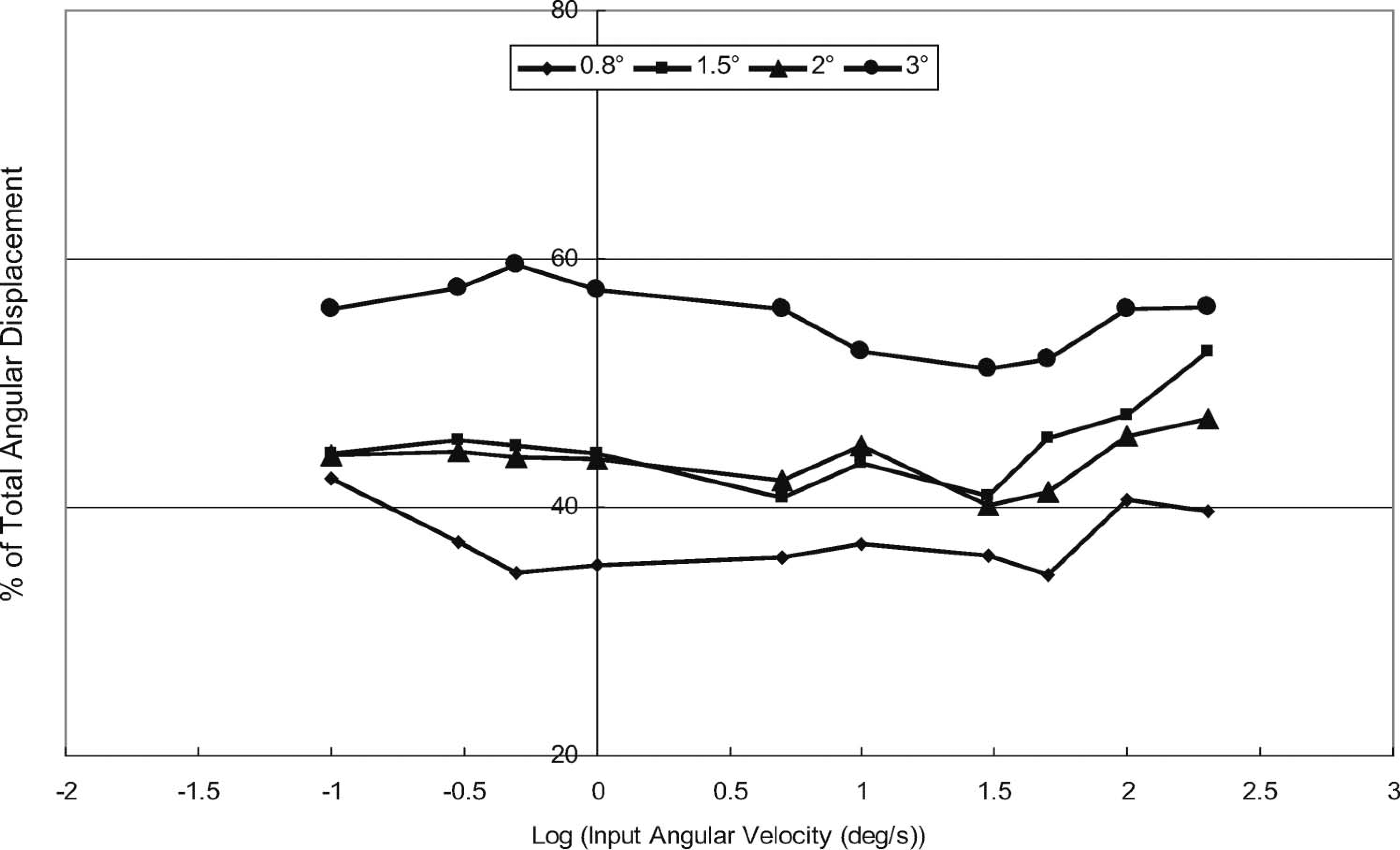
Percentage contributions of C3/4 (adjacent joint) to the total spinal deformation for different input angular displacements and velocities (angular velocity expressed in Log10 scale).
The results were further analyzed by two-way repeated measures ANOVA (SPSS 15.0, SPSS Inc., Chicago, IL, USA) with the input angular displacement and thrust velocity as the within-subject factors. There was no significant interaction between the two within-subjects factors with p = 0.254 (power = 0.910). The main effect of angular displacement was statistically significant (p = 0.013, power = 0.785). Contrast analysis reviewed that the percentage contribution of C3/4 (the adjacent inferior level) to the total angular spinal deformation significantly increased when the input angular displacement was greater than 2° (Figure 4). The main effect of thrust velocity was not statistically significant with p = 0.053 (power = 0.674). However, as it was close to 0.05, contrast analysis was also performed to investigate the changes due to different input thrust velocities. It was found that the percentage contribution of angular displacement at C3/4 was significantly lower when the thrust velocity was between 5°/s and 50°/s (Figure 5).
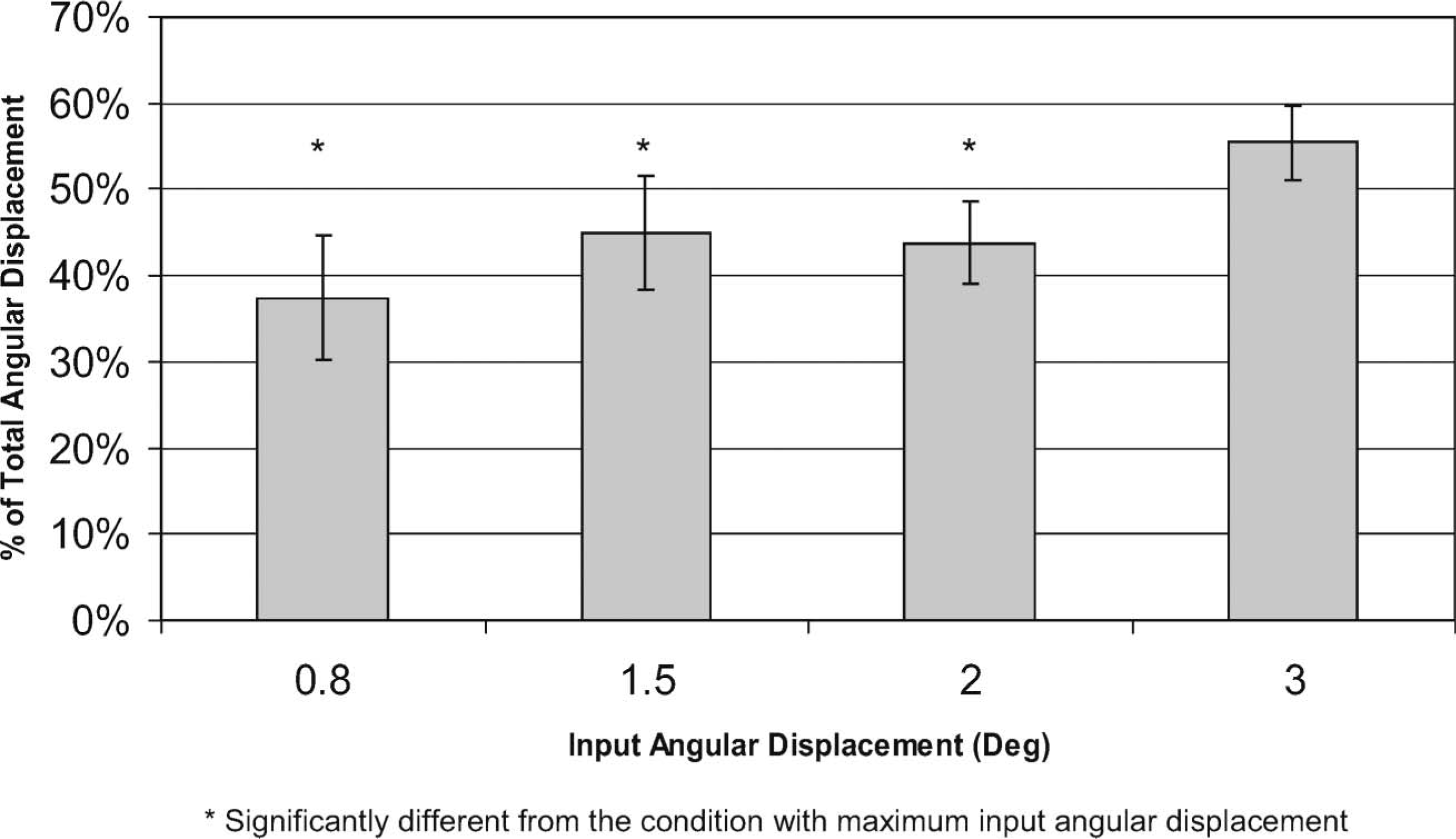
Estimated mean percentages of total angular displacement (± standard error) of C3/4 (adjacent joint) for different input angular displacements.
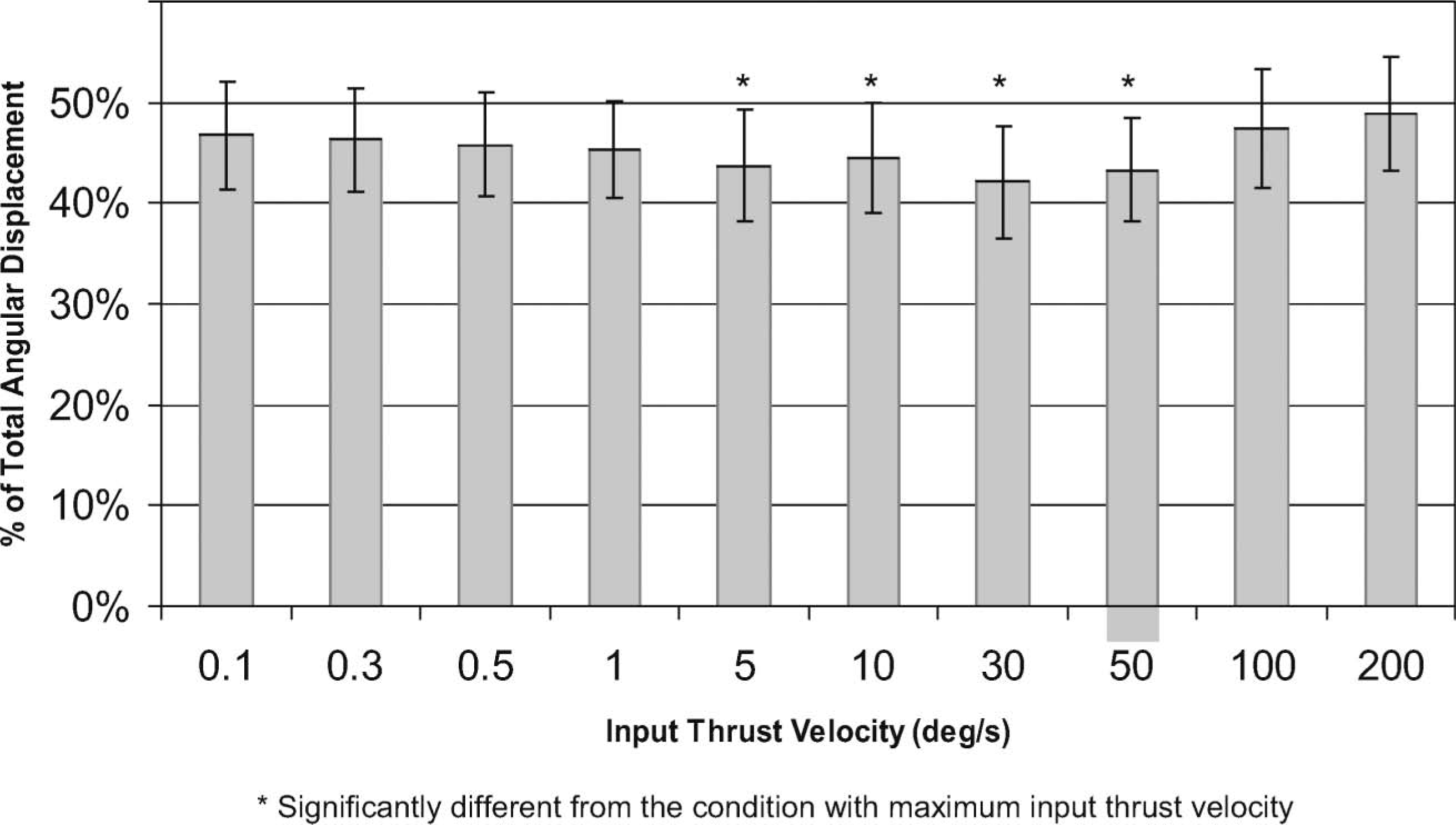
Estimated mean percentages of total angular displacement (± standard error) of C3/4 (adjacent joint) for different thrust velocities (angular velocity was expressed in Log10 scale).
Discussion
Ideally, it would be more relevant to use human cervical specimens in an in vitro kinematic analysis, but human spinal motion segments were not available. Animal specimens are homogenous and easy to obtain in quantity. Moreover, they can also be obtained from young healthy animals without pathology or degeneration. The porcine cervical spine is generally considered a good model.
In order to prevent damage of the specimen for consequent testing, the input range of rotation was increased from 0.8 – 3° gradually. Three repeated trials for every single test were done in order to enhance the reproductibility of the results. Results showed that when the input range of angular displacement increased, the percentage of angular displacement of the adjacent inferior level was increased. It was found that even when the input angular displacement was small, angular displacement of the adjacent neighbouring intervertebral level could not be avoided.
The angular velocity or thrust velocity was found to have effect on the relative rotation of the ajacent intervertebral level. It was noted that angular velocities between 5°/s and 50°/s resulted in a marked drop in the proportion of rotation at the adjacent level. Overall, the results of the analysis indicated that the relative movement was dependent on the extent and speed of rotation. It was demonstrated that angular displacements at angular velocity of between 5°/s and 50°/s seem to concentrate more the input energy on the target joint.
Haas23 used a block and spring series model (slinky dog model) (Figure 6) to explain spinal movement under manipulation. In this model, a high velocity tug over the first block will produce a large maximum distraction. If the tug is of long duration (low frequency), a succession of blocks will be set into motion producing a succession of distraction. However, if a high velocity tug of sufficiently short duration is used, little separation will be generated over the subsequent blocks. This is because distraction of the first block is completed so quickly that the inertia of the second block prevents forward movement before the first block starts the process of recoil. Ideally, a quick high velocity impulse generates significant distraction only in the block of interest. Similarly, a specific manipulation should be able to mobilize and elicit cavitation in the target vertebrae before the restoring forces can act on the adjacent segment, overcoming its inertia and setting it in motion.
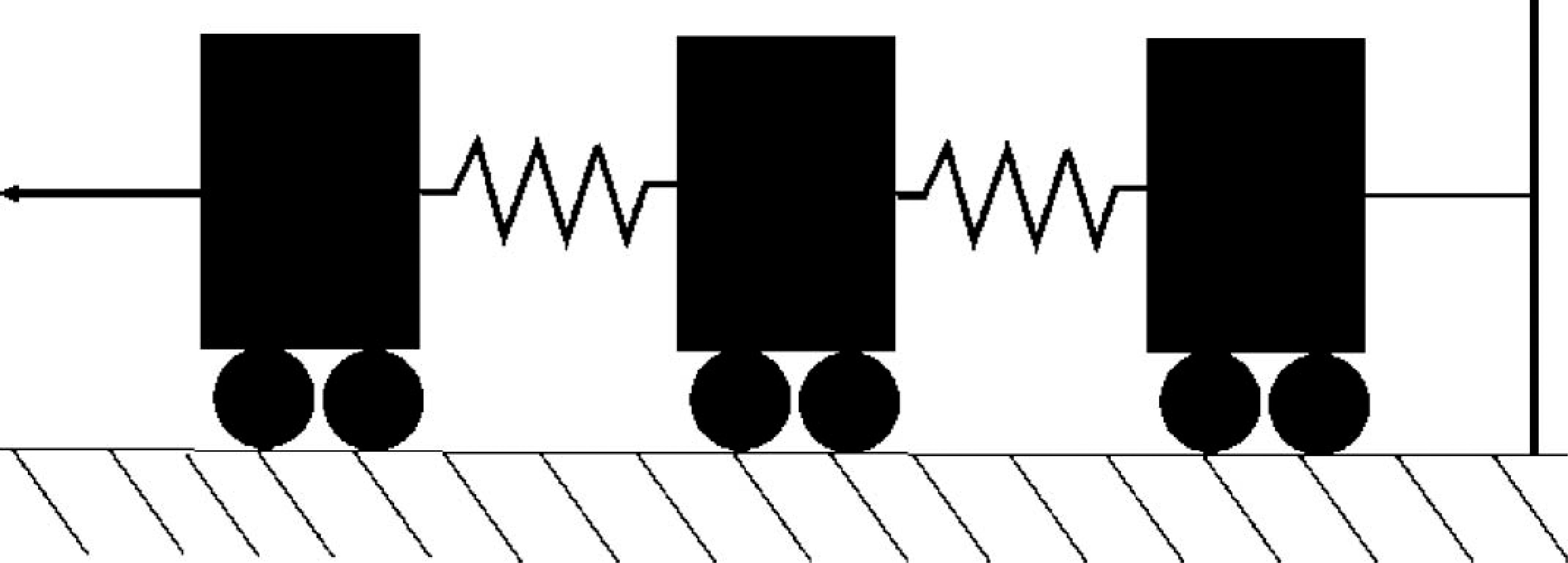
A simple load-spring model was used to illustrate the motion segments under distraction.
Haas's model [23] can partially explain why the rotation velocities of 5 – 50°/s targets the C2/3 disc. At speeds slower than 5°/s, rotation is of long enough duration to also set the C3/4 in motion. However, Haas's model fails to predict the increase in relative C3/4 motion seen at angular velocities greater than 50°/s. This is probably because Haas's model only considered elastic linkages between the inertial components, whereas the soft tissues of the spine tend to be highly viscoelastic. As a result, they will act progressively more stiffly with increasing speed of input deformation. If the rotation speed is sufficiently high, the C2/3 joint will behave like a very stiff material, where the strain within the material is low, and the energy transferred high. This will result in the majority of the input strain energy being transmitted directly through the C2/3 joint to the C3/4 joint. This is a very important phenomenon as some therapists tend to apply large force during manipulation and believed that it can ensure a success cavitation over the spine. Descarreaux et al.24 also demonstrated that students tended to apply larger force for their manipulative thrust before training. However, the result from our study suggested that due to the viscoelastic properties of the spine, high speed of movement will make the energy less efficient to be concentrated on a single particular level. On the other hand, while a high speed thrust seems desirable to target a particular level, there appear to be limits to the useful speed of the thrust. This will be especially true in cases where the joint is stiffer than normal, such as joint hypomobility. It is therefore believed that a lower speed of input is required for manipulation of a hypomobile joint.
There are several limitations in the present study. This was an in vitro animal model with no muscle forces. Clinically, even though patients may be able to relax their muscles during manipulation, the passive tension of the surrounding soft tissues will still contribute to the stiffness of the spine. Moreover, although there are similarities between pig spine and human spine, there are also fundamental differences such as the fact that pigs are not bipedal. Therefore, the functional and biomechanical properties of porcine spines are different from human spines. In addition, the pathological and degenerative changes in human spines could not be resembled in the current study using healthy porcine spines. The data obtained can only reflect the characteristics of the biomechanical properties of the spinal unit, but cannot be applied to the human spine directly. The inertia effect of the linkages between the potentiometers and the vertebral bodies were not considered in the study. Moreover, the axis of rotation of a functional spinal unit is not fixed in vivo. However, in the present experiment, the specimen was fixed in dental plaster, and the rotation will therefore be restricted to be around a fixed axis. Therefore, the specimen will be subject to considerable shear stresses, which were not recorded, and the analysis was restricted to only one degree of freedom.
When performing a spinal manipulation, the proximal part of the spine is fixed by the therapist while the distal part is free to move. We believed that the rapid thrust of manipulation is used to direct the input energy and motion at the target level with minimal interference at the adjacent neighboring levels. However, in our experimental arrangement, we have little choice but to fix the distal end of the specimen, and therefore will not accurately resemble the real situation. Because the specimen is fixed in the testing machine, it is impossible to replicate a realistic pre-manipulation position, which includes flexion of the cervical spine. The in vitro kinematic study presented here can therefore, only be considered as a first approximation to the situation in vivo. Nevertheless, we believed that the observed medium velocity range for applying rotational manipulation to a target joint also exists in human spine. Further study using human cadaveric spine specimens is recommended for determining the actual limits of the medium velocity range for rotational manipulation.
Conclusion
The percentage of total angular displacement induced at the adjacent inferior level during simulated rotational manipulation was found to be dependent on the input angular displacement and thrust velocity. With the hypothesis that rapid thrust of manipulation is used to direct the input energy and motion at the target level with minimal interference at the adjacent levels, the applied angular displacement should not be too large and the thrust velocity should be within a medium velocity range.
Footnotes
Acknowledgements
This work was supported by the Hong Kong Polytechnic University central research grants G-V570 and G-YY28.