
Abstract
The influence of mould level instability during continuous casting on the unevenness of the initial solidified shell in hypo-peritectic steels has been investigated. Water model experiments and in-plant casting experiments revealed that mould level instability, which increases with increasing casting speed, is related to longitudinal cracking resulting from the unevenness of the solidification shell. A numerical model which considers the effect of mould level instability was developed and used to simulate the formation of the unevenness of the solidification shell and solidified shell deflections. The calculation results show that an increase in the non-uniform infiltration of mould flux increases the unevenness of the solidified shell. On the other hand, the unevenness of the solidified shell decreases due to mild cooling. Overall, the results of the plant tests and calculations show that non-uniform infiltration of mould flux dramatically affects air gap formation and the unevenness of the solidified shell.
Nomenclature
mould level drop along wide wall side in water model experiment (mm).
average water level fluctuation over 60 s at 1/2 thickness and 1/8 width in water model experiment (mm)
index of mould level fluctuation at 1/2 thickness and 1/8 width in plant experiment [−].
steel heat capacity (0.68 kJ/kg/°C)
liquidus temperature (°C)
solidus temperature (°C)

steel latent heat (272.1 J/g)
heat-flux profile of mould flux A (W/m2)
heat-flux profile of mould flux B (W/m2)
casting speed (m/min)
difference in solidification height between R3 and R1 (mm).
difference in solidification height between R3 and R2 (mm).

heat fluxes in R1 (W/m2)

heat fluxes in R2 (W/m2)

heat fluxes in R3 (W/m2)

temperature of water in mould (298 K)

baseline thermal resistivities of R1 (m2K/W)

baseline thermal resistivities of R2 (m2K/W)

thermal resistivity variation caused by air gap and change in solidified shell thickness of R1 (m2K/W)

thermal resistivity variation caused by air gap and change in solidified shell thickness of R2 (m2K/W)

parameter of non-uniform infiltration of mould flux

thermal resistivity of air gap (m2K/W)

thermal resistivity of solidified shell with air gap (m2K/W)
ferrostatic pressure (Pa)

gravitational acceleration (m/s2)
distance from meniscus (mm)


constants
gas constant (J/K/mol)
activation energy for deformation (J/mol)
strength coefficient
strain hardening exponent

effective plastic strain [−]

plastic strain rate [1/s]
calculated air gap height (μm)
shell thicknesses in R3 (at x = b)
shell thicknesses in R1 (at x = 0)
Introduction
Longitudinal cracks on the slab surface are one of the most serious defects that can occur during continuous casting [1–3]. These cracks reduce not only the surface quality of a slab but also productivity [4]. Longitudinal cracks are especially pronounced in hypo-peritectic steels since the δ to γ transformation induces large shrinkage within the solidified shell as well as unevenness in its thickness, which leads to solidified shell deflections [5–9].
Many numerical simulations have been performed on the shell deflection behaviours that occur when an air gap exists between the mould and the solidified shell during the δ to γ transformation [10–14]. The effect of the width of the air gap and the ferrostatic pressure at the boundary between the solidified shell and the liquid in the mould on longitudinal crack formation has also been reported by several researchers [10]. In our previous work [11], the authors evaluated the influence of the cooling rate and the width of the low heat flux region on the height of the air gap and the unevenness of the solidified shell. The results revealed that suppression of the non-uniformity of mould flux infiltration and optimization of the cooling rate are important for preventing longitudinal cracking.
It is known that the mould level instability that occurs with high casting speeds decreases the uniformity of mould flux infiltration and thus increases slab longitudinal cracking [3,15–17]. However, no numerical studies to date have examined the combined influence of mould level instability and mould flux infiltration on the resulting air gap formation and solidified shell unevenness.
In this study, water model experiments were carried out in order to clarify the effect of the casting speed on the relationship between mould level instability and mould level fluctuation. In-plant casting experiments were also conducted to clarify the relationship between mould level instability and longitudinal cracking, which is expected to affect the initial stages of solidification. In particular, mould level instability is considered to cause non-uniform mould flux infiltration, which might be one origin of the air gap. Based on the experimental results, a numerical model which considers non-uniform mould flux infiltration and the difference of the initial solidification point was developed, and their effects on the air gap formation of the solidified shell in hypo-peritectic steels were investigated. The validity of the model was then demonstrated by comparing the simulated results with industrial continuous casting data.
Experimental method
Water model experiments
The influence of casting speed on mould level fluctuation and instability were investigated using a full-scale mould water model. The conditions of the water model experiment are listed in Table 1. The throughput was calculated by using the Froude number approximation between water and steel for continuous casting. Both the mould level drop along the wide wall side (Ld
) and the average water level fluctuation over 60 s at the 1/2 thickness and 1/8 width (Lw
) were measured by using an ultrasonic water level sensor, as shown in Figure 1. The mould level instability indicated by Ld
around the side wall of the mould represents a state whereby the level has changed for several seconds. This mould level instability is a much different phenomenon from normal mould level fluctuations, such as a hunching of the top of the surface, that occur at a frequency of greater than 1 Hz but are non-stationary, and have a significant effect on the initial stages of unevenness in solidified shell deformations. Schematic diagram of mould level instability (Ld
), mould level fluctuation (Lw
) and flow in water model experiment. Water model experiment and plant test conditions.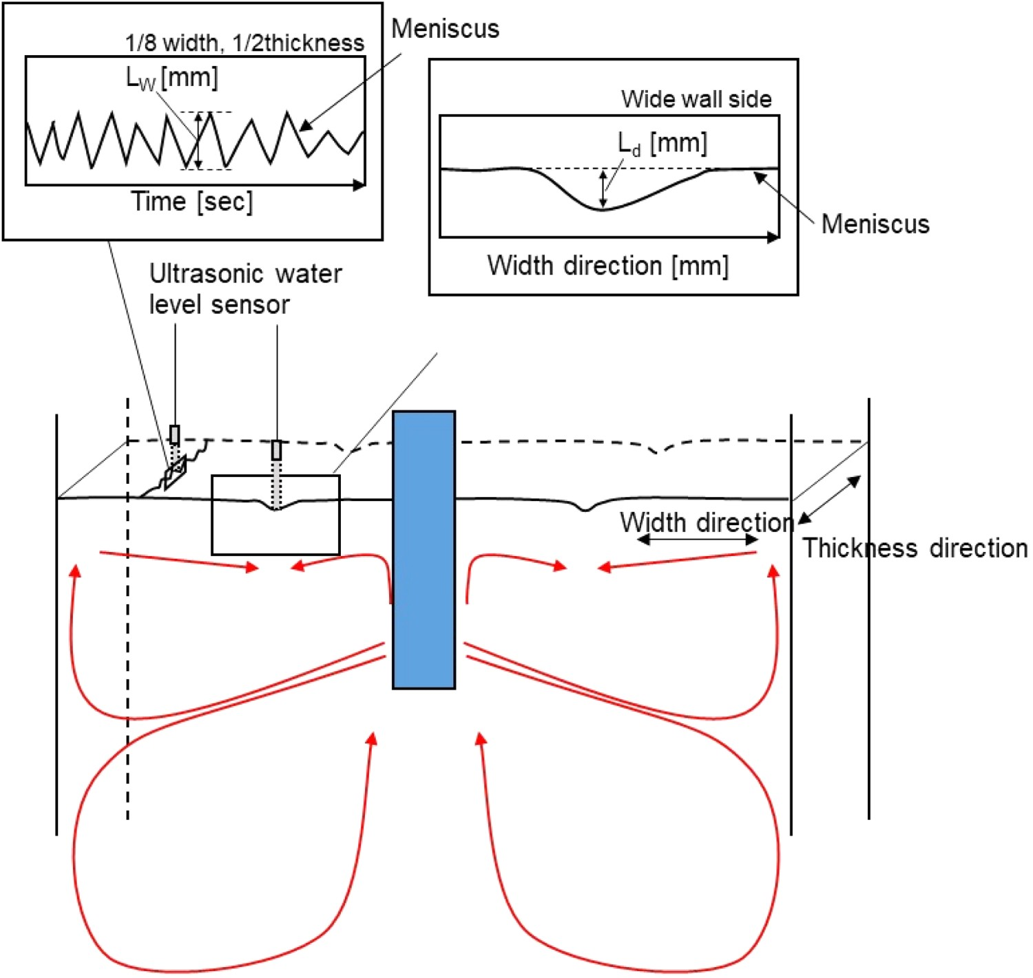
In-plant casting experiments
A series of plant trials was conducted using the experimental casting conditions and properties of the mould flux also shown in Table 1. The chemical compositions of the steels were Fe-(0.09–0.13)%C-0.20%Si-(0.80–1.45)%Mn-0.01%P-0.002%S, which were all within the hypo-peritectic steel range, while the basicity of the mould flux and the solidification temperature were 0.92 and 1 373 K, respectively. The mould level fluctuation at the 1/2 thickness and 1/8 width (Lp ) was measured using an eddy current sensor. The measurement of mould level instability was technically difficult due to the presence of the mould flux and high temperature, although several special methods have been proposed to measure the mould level instability [18,19]. Mole levels were instability and therefore not measured in this study. After continuous casting, the number density of longitudinal cracks on the slab surface was measured.
Mathematical model
A sequentially-coupled heat transfer and solidified shell deformation analysis was performed employing the commercial FEA package ABAQUS assuming a 0.10 wt-% C hypo-peritectic steel alloy. A schematic of the model domain in the calculation is shown in Figure 2. The thermal model, Figure 2(a), consists of a quarter cross-section of a slab 220 mm in thickness and 1500 mm in width that contains both liquid and solid steel. The deformation model, Figure 2(b), consists of a half-section of the solidified shell along the wide face. Geometries used for FEA (a) thermal model and (b) stress model.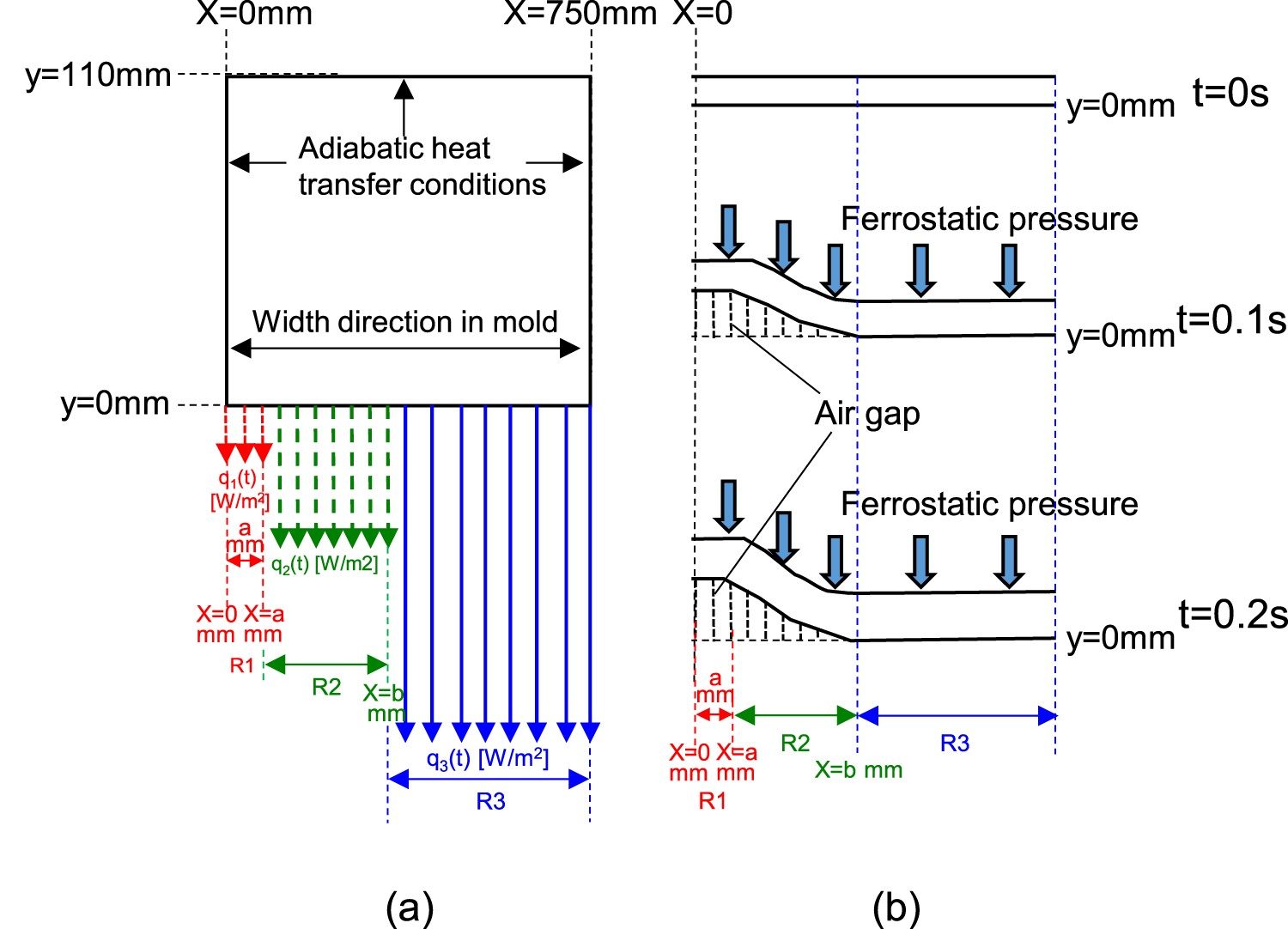
Heat transfer calculation
2D unsteady heat-transfer equations were employed to calculate the temperature distribution in a transverse slice of the strand in the mould. In order to consider the effect of latent heat, the equivalent specific heat method expressed in Equations (1) and (2) was utilized [10,12].

The heat flux profiles measured by Kanazawa et al. [21]. were used as input values in the present study to simulate casting. Kanazawa measured the heat flux occurring when using different mould fluxes at a position 45 mm below the meniscus for a range of casting speeds up to 5.0 m min−1. In this study, the measurements for two mould fluxes (high and low heat flux, mould flux A and mould flux B) expressed by the casting speed were converted to heat flux profiles expressed by the transit time from the meniscus. The transit time is given as the ratio of the distance from the meniscus to the measurement thermocouple (45 mm) and the casting speed. The discrete points were then fit to exponential-type empirical equations for data extrapolation. To estimate the heat-flux profile for the two types of mould fluxes listed in Table 2 [21] (mould fluxes A, q
MF-A, and B, q
MF-B) near the meniscus region, exponential-type empirical equations were employed, as shown in Figure 3. Since this study does not deal with a fluid flow, but only with heat transfer and shell deformation, the only influence of flux properties is the heat flux that leads to the cooling rate. It was confirmed in the previous study that Mould flux B has a slower cooling behaviour for the solidified shell, corresponding to lower heat flux in the mould, than mould flux A [21]. In addition, the present calculation results showed that mild cooling in the mould greatly reduces the unevenness in the solidified shell. The wide face surface is divided into three regions: a drop in the meniscus shape and low heat flux region at the centre of the slab (R1, 0 < x < a), where longitudinal cracks easily occur because of the local solidification delay with the low heat flux resulting from non-uniform infiltration of the mould flux due to mould level instability, a shell deflection region (R2, a ≤ x ≤ b) and a normal region (R3, b < x), as shown in Figure 2. Since there is little knowledge about the relationship between mould flux infiltration and mould level instability, it is presumed that the amount of mould flux infiltration into the channel between the solidified shell and the mould increases due to the enlarged channel and high infiltration rate into the channel accompanying large mould level instability during continuous casting [17]. The heat flux profiles in R1 were approximated as 40%, 60%, 80% or 100% of the original heat flux profiles (q
MF-A or q
MF-B) applied to R3 to describe the non-uniform infiltration of the mould flux near the meniscus due to mould level instability. Note that the effect of viscosity on the mould flux infiltration is assumed to be large, but it is ignored in this calculation for simplicity. Variation in applied heat flux as function of transit time from meniscus for mould fluxes A and B. Mould flux properties of mould fluxes A and B.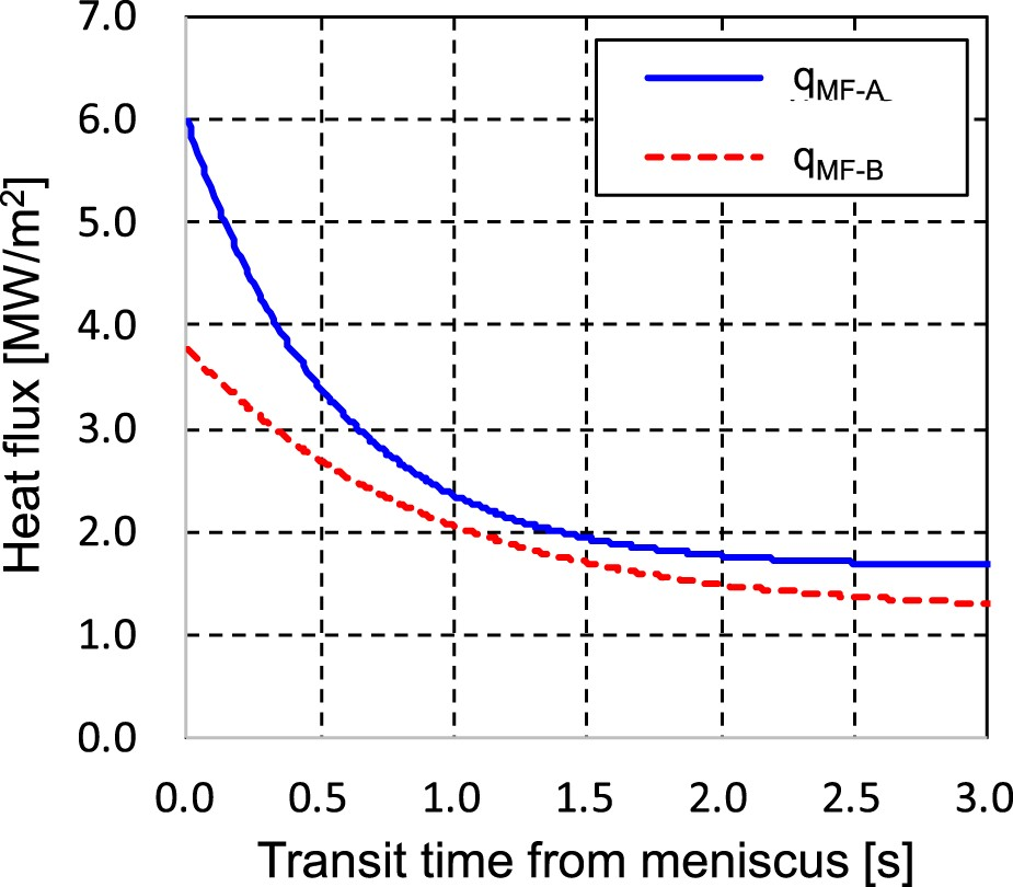
Figure 4 shows a schematic diagram of additional model details, including the relevant dimensions as well as the numerically modelled influence of mould level instability on the heat flux distribution. As can be seen from this figure, the initial solidification point is delayed in R1 as compared to R2 and R3. The differences in the solidification height between R3 and both R1 and R2 correspond to the values of mould level instability LR1
and LR2
. The time difference t′ and t″ between the start of solidification in R3 and in R2 and R1 can be expressed as. Schematic diagram of influence of mould level instability on solidification delay in mould.

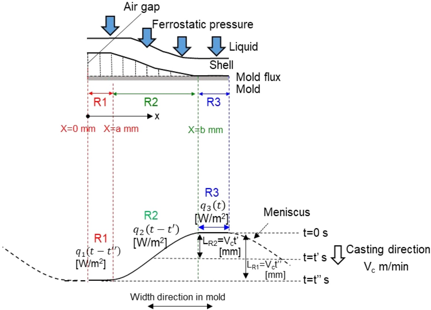
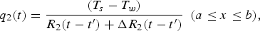
The heat fluxes at t > 0 in the three regions including the influence of mould level drop are given by.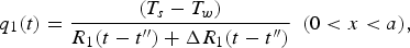


The variations in the thermal resistances in R1 and R2 are given by.


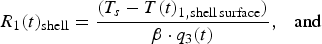
The values of 


Solidified shell deformation calculation
The ferrostatic pressure at the boundary between the solidified shell and the liquid metal was applied to the shell as shown in Figure 2. The ferrostatic pressure can be expressed as


Model implementation
The numerical simulation was carried out as follows. First, the heat transfer calculation was performed by applying heat flux on the surface of the solidified shell taking the non-uniform mould flux infiltration and setting the initial temperature of the liquid steel to be TL
+ 10°C of industrial process condition. Second, a δ to γ transformation calculation was carried out to determine the density change and thermal expansion in a solidified shell experiencing different cooling rates, and the resulting air gap was calculated. Third, the heat flux at the next time increment for each domain was estimated based on the calculated air gap height (h
air-gap). A time step of 0.1 s and a mesh size of 0.2 mm were employed. Unless otherwise noted in these simulations, the values of 
Results and discussion
Water model experiments
First, the mould level instability and fluctuation measurements, i.e. Ld
and Lw
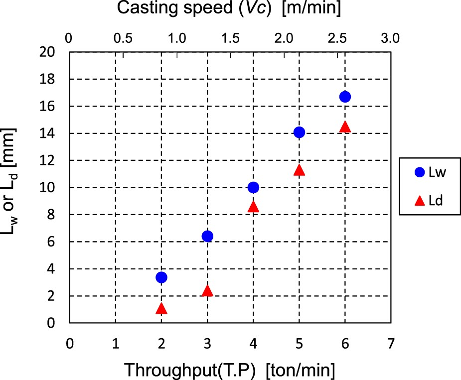
, and observation of the flow in the mould were conducted with the water model. The results are shown in Figure 5 as a function of throughput (T.P) and Vc
. Although the origin of Ld
formation is different from that of Lw
, both Lw
and Ld
increase with increasing Vc
. Especially, Lw
increases linearly with increasing T.P, while a jump in Ld
is seen to occur at high throughput conditions when T.P exceeds 4 t min−1. From the shape of the mould level drop observed along the wide front side of the water model experiments, Ld
is caused by the collision of the complicated mould flow, with the values of a and b in Figure 4 falling between 0.5–2.0 and 2–10 mm, respectively. Note that although the parameters a and b are greatly affected by in mould flow, the model calculations were performed in the range of 0.5–2.0 mm of a and 2–10 mm of b.
Lw
and Ld
measured in water model experiments as function of T.P and Vc.
Plant experiments
Figure 6 shows the results of the plant test of the relationship between the index of Lp
and the index of longitudinal surface cracks on slabs under different Vc
conditions. The mould flux consumption was between 0.3 and 0.6 kg m−2 under different Vc
conditions. Note that the mould flux infiltration decreased with increasing Vc
. Most of the longitudinal surface cracks occurred around the 1/4 width or 3/4 width position, which correspond to the mould level drop positions in Figure 1. It should be noted that the average Lp
and the longitudinal surface crack number at Vc
= 1.5 are defined as 1.0 of the index Lp
and the index of longitudinal surface cracks, respectively. It was found that both Lp
and the index of longitudinal surface cracks increase with increasing Vc
. Especially, the index of longitudinal surface cracks increases remarkably in the high Vc
condition. According to the water model results shown in Figure 5, Ld
increases with increasing Vc
as well as Lw
corresponding to Lp
. Therefore, it is assumed that Ld
significantly affects the initial stage of solidification, and the increase in the index of longitudinal surface cracks might be attributed to Ld
rather than Lp
. Relation between index Lp
and index of longitudinal surface cracks in plant tests with slabs under different Vc
conditions.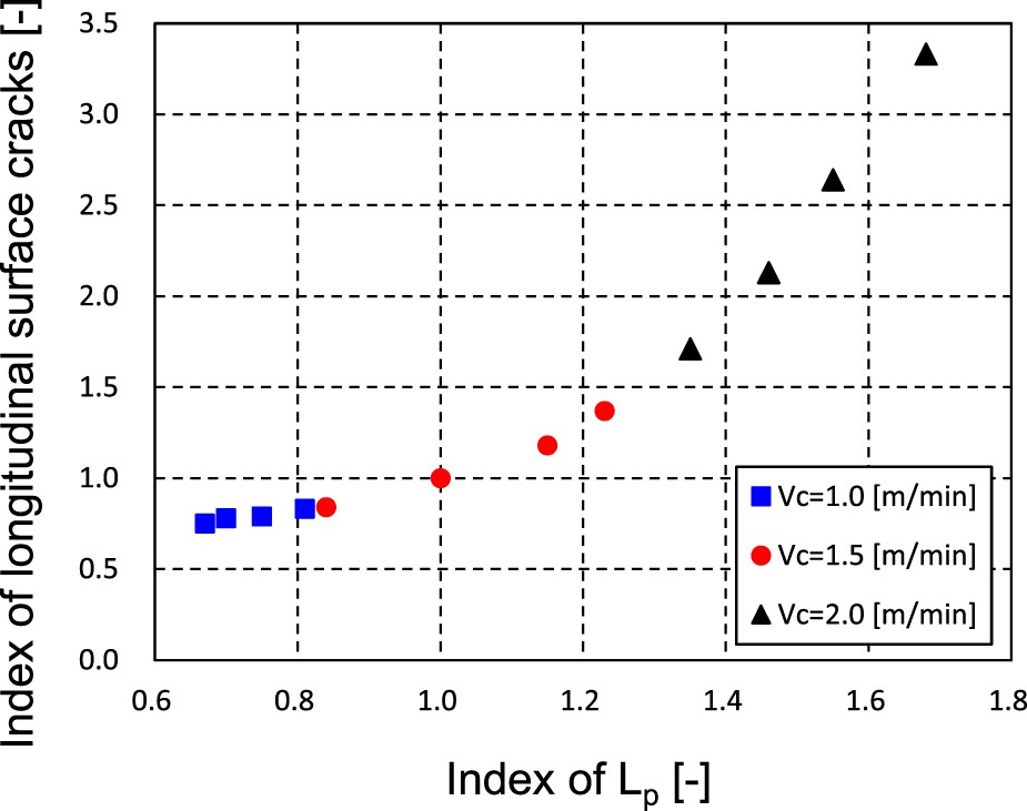
Effect of mould level instability on unevenness of steel solidification by calculation model
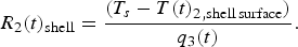
The increase of local mould flux infiltration leads to a local solidification delay due to the increase of thermal resistance and might arise from the air gap. The origin of non-uniform mould flux infiltration might be mould level instability, as mentioned previously. In order to evaluate the effect of the uniformity of mould flux infiltration along mould width direction, (1) the height of the air gap at x = 0 (h
air-gap(x = 0)) and (2) the unevenness of the solidified shell (σ) as a function of Influence of β on (a) h
air-gap(x = 0) and (b) σ for mould fluxes A and B.


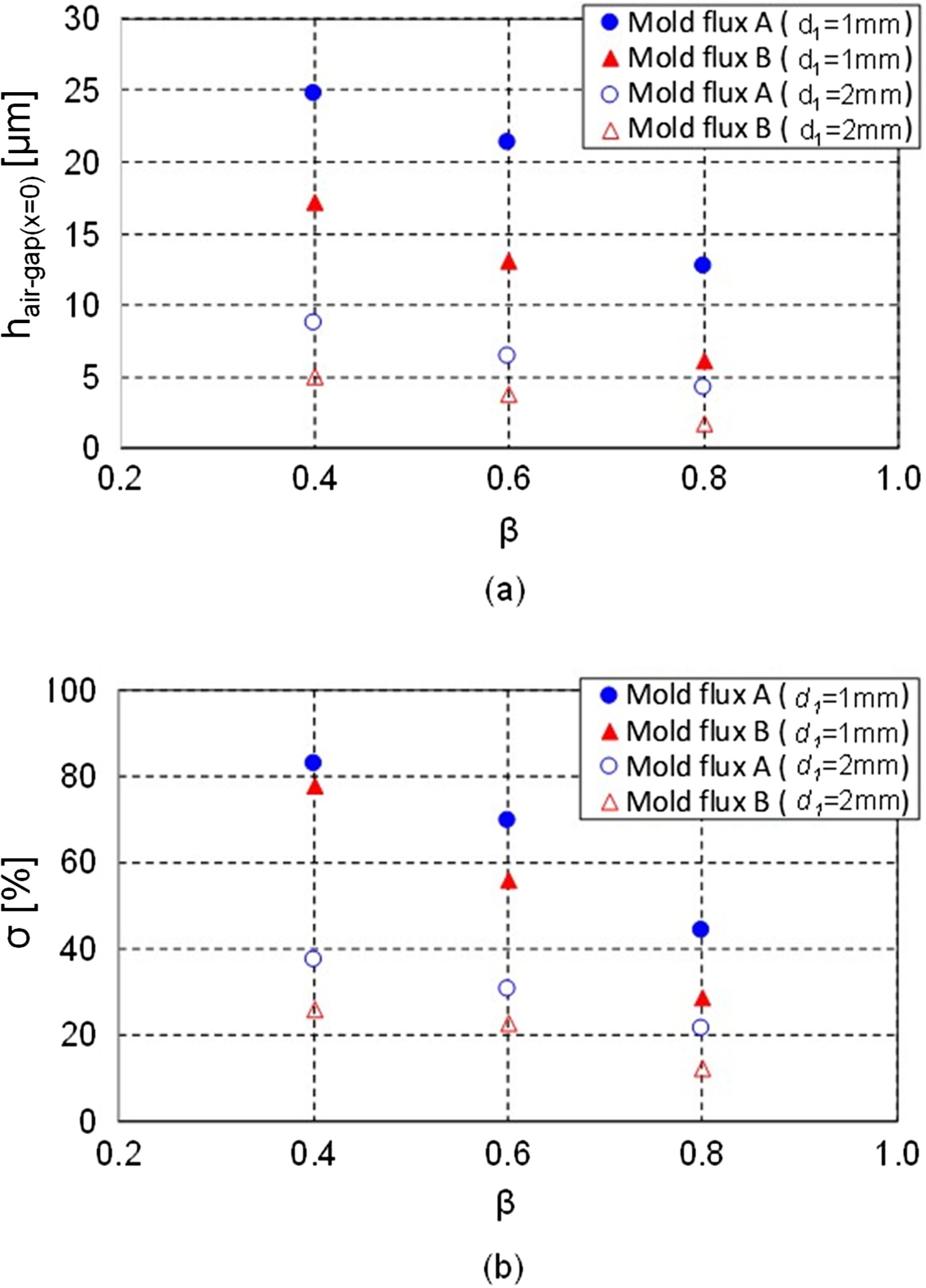
It is assumed that 

The relationship between Z corresponding to Vc
at d
1
= 2 mm and hair-gap(x = 0) at the different b values of 2.5, 5.0 and 7.5 mm without mould level drop (L
R1 = L
R2 = 0) are shown in Figure 8. In all cases, h
air-gap(x = 0) decreases linearly with increasing Z due to the increasing ferrostatic pressure. As can be seen, the slope of Figure 8 increases with increasing b. Although it is difficult to estimate what factors decide the value of b, it has been reported that the value of b is related to the condition of solidified shell sticking to the mould [11], and it is assumed that the condition of solidification delay might be related to the behaviour of mould flux infiltration caused by the mould level instability and flow in the mould as well as a. Relation between Z corresponding to Vc
at d1 = 2 mm and hair-gap (x = 0).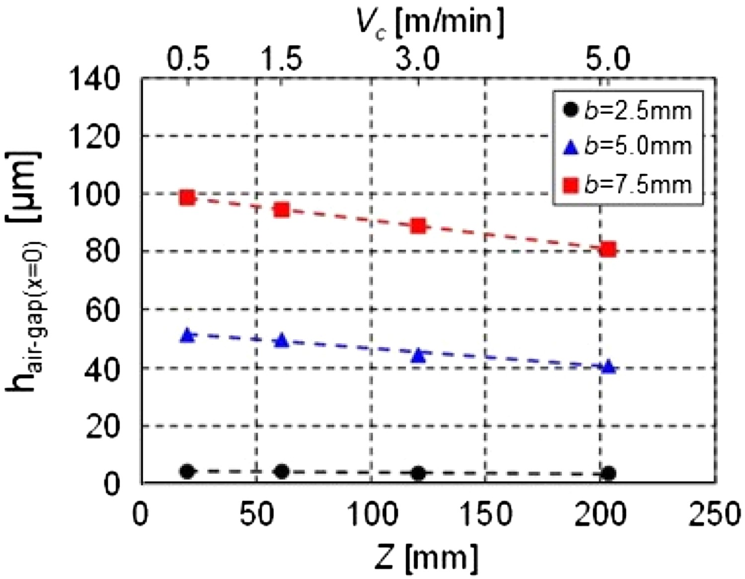
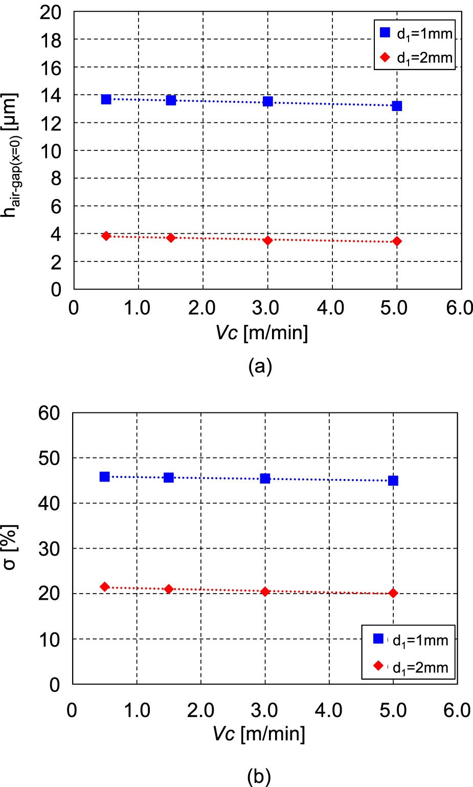
Figure 9 shows (a) h
air-gap(x = 0) and (b) σ at d1
of 1 and 2 mm as a function of Vc
with the same values of a and b. From these calculations, it can be seen that just increasing Vc
results in a slight decrease in h
air-gap(x = 0) and σ. The reason for the decreasing h
air-gap(x = 0) and σ with increasing Vc
is because P increases with increasing Vc
at the same t from the meniscus. As shown in Figure 6, the plant test results show that the number of longitudinal cracks on the slab during continuous casting increases with increasing Vc
. From these results, it is found that only an increase in Vc
does not lead to an increase in longitudinal cracks, but that other phenomena due to the increase in Vc
are related to the increase in the number of cracks. Since the same mould flux was used in the plant test under different Vc
conditions, the effect of the mould flux on the difference in the number of longitudinal cracks due to Vc
increase is assumed to be small. Influence of casting speed Vc
on (a) h
air-gap(x = 0) and (b) σ.
Local solidification delay, leading to unevenness of the initial stage of solidified shell, might be induced by the mould level instability with the drop of the meniscus shape at the mould wall observed in the water model experiment, as shown in Figure 5. In order to simulate the influence of the meniscus shape due to increasing Vc
on hair-gap and σ, the initial solidification starting time differences t′ and t″ shown in Equations (3) and (4) were introduced in the numerical calculation. It should be noted that Vc
and LR1
are independent parameters in this model, although L
R1 increased as Vc
increased in the experiment, as shown in Figure 5. The contour plots of the calculated solidified shell displacement as a function of mould level instability LR1
of 5, 10, 15 and 20 mm at d
1 of 1 mm are shown in Figure 10. Here, the deformed geometries of the solidified shell are magnified by five times. It is confirmed that hair-gap increases with increasing LR1
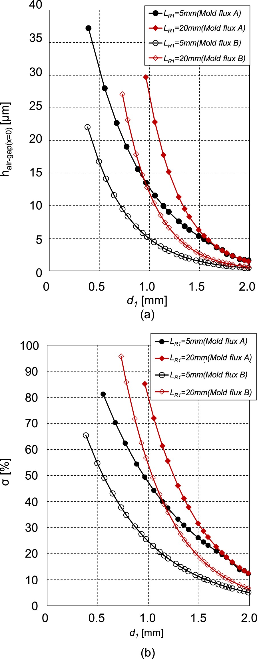
. Figure 11 shows (a) h
air-gap(x = 0) and (b) σ as a function of d
1 at different values of L
R1 for mould flux A. h
air-gap(x = 0) and σ both increase with increasing L
R1 at the same d
1. These values of h
air-gap(x
=
0) and σ dramatically decrease with increasing d
1. Contour plots of solidified shell displacement at value of mould level instability of (a) L
R1
= 5 mm, (b) L
R1
= 10 mm, (c) L
R1
= 15 mm and (d) LR1
= 20 mm at d1
= 1 mm. The deformation geometry has been enlarged by 5 times. Influence of LR1
on (a) h
air-gap(x = 0) and (b) σ as function of d
1 for mould flux A.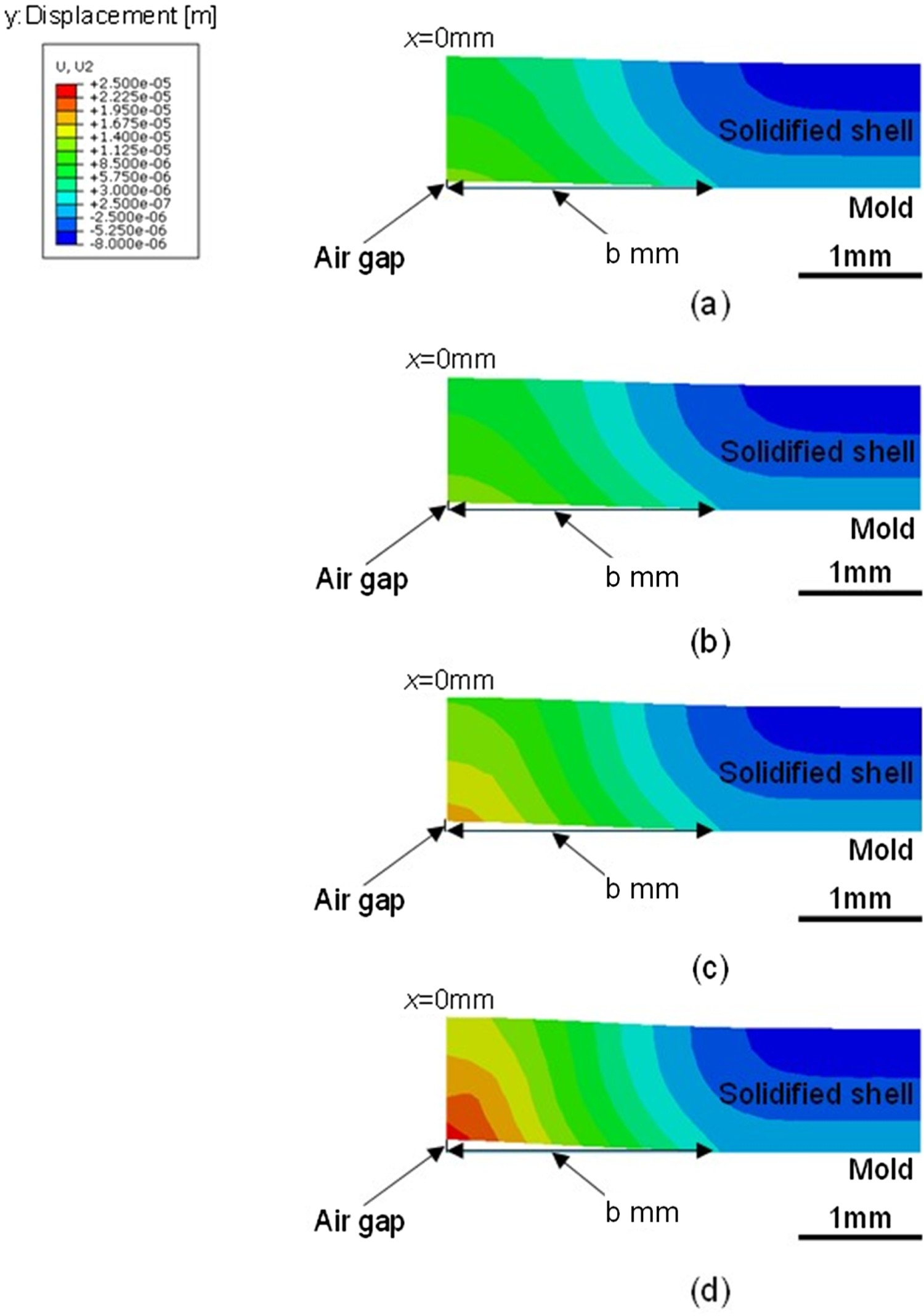
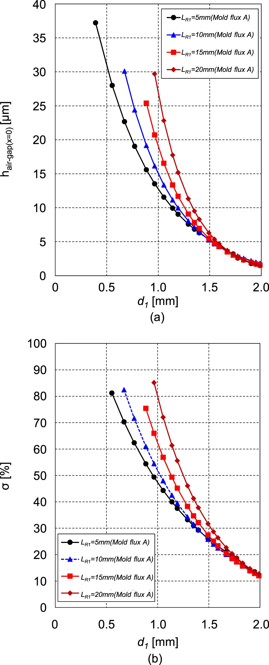
Figure 12 shows a comparison of (a) h
air-gap(x = 0) and (b) σ with mould fluxes A and B at the values of L
R1 of 5 and 20 mm as a function of d
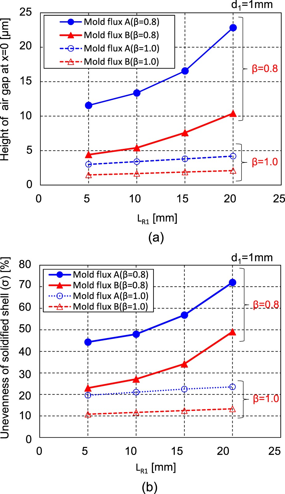
1. To further quantify the effect of the mould flux properties on (a) h
air-gap(x = 0) and (b) σ as a function of LR1
and Comparison of (a) h
air-gap(x = 0) and (b) σ with mould fluxes A and B at L
R1 of 5 and 20 mm as function of d1
for both mould fluxes. Effect of mould flux on (a) h
air-gap(x = 0) and (b) σ as function of L
R1 and β.


Based on these results, it can be stated that a high casting speed during continuous casting easily causes large mould level fluctuation, mould level drop and non-uniform mould flux infiltration, leading to longitudinal cracks on the slab. However, it is clear that better control of the occurrence of mould level instability and non-uniform mould flux infiltration by using a mould flux that has lower cooling characteristics for the solidified shell (e.g. mould flux B) will reduce longitudinal crack formation.
Conclusion
Water model experiments of the mould flow in continuous casting were conducted to reveal the effects of the casting speed on mould level instability and mould level fluctuation in the mould. In-plant casting experiments were also conducted to reveal the effect of the casting speed on the increase in the number of longitudinal cracks. Furthermore, in order to evaluate the influence of mould level instability and non-uniform infiltration of mould flux on the unevenness of the solidified shell of hypo-peritectic steels, these factors were evaluated using a new calculation model that is able to consider their effects.
The mould level drop that is caused by the complicated mould flow under high throughput conditions was observed in the water model experiment. In-plant casting experiments revealed that the number of longitudinal cracks increased by the mould level instability with the drop of the meniscus shape at the mould wall under the higher casting speed conditions. From the calculation and experimental results, the height of the air gap and σ both increase as the amount of mould level drop increases. Moreover, this study confirmed that non-uniform infiltration of mould flux into the mould level drop has a large influence on the unevenness of the solidified shell. Based on these results, it is clear that better control of the occurrence of mould level instability and non-uniform mould flux infiltration by using a mould flux that has lower cooling characteristics for the solidified shell will reduce longitudinal crack formation.
Footnotes
Disclosure statement
No potential conflict of interest was reported by the author(s).