
Abstract
HIsarna reactor is characterized by a high raw materials versatility and is therefore attractive for processing secondary iron sources. Among the materials that can be recycled through HIsarna, zinc-bearing material has drawn a special attention. Based on the plant data, once dust-containing Zinc was injected into the main reactor, a final collected dust with a zinc content of 16% was achieved which opened up possibilities of higher enrichment for direct reuse in Zn smelting as a secondary source and an alternative for Zn ore (the primary source). However Zn vapor can react with iron oxide to form zinc ferrite (ZnFe2O4), which is an undesired product. Hence, the main focus of this study is to minimize the formation of ZnFe2O using thermodynamic (FactSage) and computational fluid dynamic tools. After detecting regions with high potential of ZnFe2O4 formation, proper geometrical and operational modifications of the off-gas system is proposed to minimize the formation of zinc ferrite.
Nomenclature

absorption coefficient

coefficients are constant
total energy [J kg–1]

drag force [N]

gravitational acceleration [m s–2]

production terms

spectral radiation intensity

diffusion flux of species

effective conductivity of fluid [W m–1 K–1]

turbulent kinetic energy [m–2 s–2],

particle mass [kg]

spectral index of refraction of the medium

pressure [Pa]

position vector [m]

net rate of chemical reaction

direction vector

heat of chemical reaction

source term
temperature
time

fluid phase velocity [m s–1]

particle velocity [m s–1]

fluctuating velocity [m s–1]

mean velocity

destruction terms
Greek letters
Stefan–Boltzmann constant

scattering coefficient

solid angle

effective diffusivities [kg m–1 s–1]

dissipation frequency [1 s–1]

turbulent viscosity [m–2 s–1]

molecular viscosity [kg m–1 s–1]

density of fluid [kg m–3]

density of the particle [kg m–3]

particle relaxation time

turbulent Prandtl number for kinetic energy = 1

turbulent Prandtl number for energy dissipation = 1.2
Introduction
Zinc (Zn) industry demands Zn ore at an acceptable price, but is also very interested in secondary resources as well to offset the need for prime ores. The availability of prime Zn ore and concentrates is declining and therefore driving up prices. Thus, there is an increasing interest in suitable secondary resources of Zn concentrates. One feasible way is to extract Zn from by-products and waste streams and reusing it for Zn production. This can contribute to reducing the need for landfilling, or even opens the possibility to process the contents of existing landfills and tailings, and ultimately lessening their environmental impacts and contributing to circular economy.
The steel industry produces large volumes of Zn-coated (galvanized) products which can be easily recycled via the electric arc furnace (EAF) route. In this route, scrap is charged into the furnace and is heated by means of an electric arc. The charged materials are melted to form slag and metal layers while Zn is vaporized and along with slag particles forming a fume (also known as dust) that escapes from the top space [1]. The EAF dust is rich in Zn, which is generally in the order of 7% to 40%, depending on the zinc content of the utilized scrap [2–6]. Havlik et al. [7] have reported an average of 22.14% Zn content based on a review of 19 different experimental resources with minimum and maximum of 13% and 39%, respectively.
During the EAF process, the Zn element can speciate into either zinc oxide (ZnO) or zinc ferrite (ZnFe2O4) compound. If the amount of ZnO in the dust is high enough, then it can be directly used in the Zn smelting process to produce pure metallic Zn. However, the presence of ZnFe2O4 and also iron oxide compounds (on average 31% [7]) in the dust does require additional processing steps (pyro and hydrometallurgical routes) to enrich ZnO content before it is suitable for smelting application [1,2,8]. The most common routes are pyrometallurgical routes such as the Waelz kiln process which are characterized by high Zn recovery efficiency and also high energy consumption and pollutant emission. On the other hand, hydrometallurgical routes are less energy intensive and more eco-friendly, but complete recovery of Zn has proved to be very difficult due to the stability of ZnFe2O4 [7,9]. If Zn content in the initial dust is mainly in the form of ZnO, high recovery efficiency is to be expected for any recovery routes [9].
The HIsarna process is a new concept based on the smelting reduction technology for producing liquid carbonated iron directly from iron ore and coal. Compared to the blast furnace route, coking and iron ore agglomeration (sintering and pelletizing) processes are eliminated, which inherently leads to at least 20% reduction in CO2 emission. Further reduction up to 80% can be achieved by incorporating carbon capture and storage technologies.
Based on the plant data and analysis which will be discussed in the coming sections, the process is characterized by high raw material versatility and is therefore attractive for processing secondary iron sources similar to the EAF process. Among the materials that can be recycled through HIsarna, galvanized steel scrap, basic oxygen furnace dust and zinc-bearing briquettes worth mentioning.
Based on the laboratory analysis of the collected dust in upstream, considerable amount of Zn in the form of ZnFe2O4 and ZnO was detected. This finding led HIsarna technologists and researchers to believe that by injecting zinc-bearing material into the process, the Zn content is evaporated and concentrated in the off-gas dust (similar to the EAF process). However, it is desired to obtain a dust with the minimum content of ZnFe2O4 (rich in ZnO) from which it is more convenient to recover Zn element.
In this study, the HIsarna process is described and then using thermodynamic (FactSage) and computational fluid dynamic (CFD) tools, the regions with a high risk of ferrite formation are detected inside the main reactor and off-gas system. According to findings, with current operation and configuration, the formation of ZnFe2O4 is inevitable and can only be minimized through proper geometrical and operational modifications. The study is mainly based on thermodynamic equilibrium calculations and the effect of kinetics is not considered. Since the current system is a mixture of complex surface and volumetric reactions, thermodynamic calculations will be useful to have qualitative analysis on the behaviour of Zn vapour. For detailed quantitative analysis, incorporating kinetics is required which is the topic of another future study by the same authors.
HIsarna process
A pilot scale process flowsheet is shown in Figure 1(A). The process is currently at the development stage at Ijmuiden site of Tata Steel in the Netherlands and since 2010 is fully operating with the capacity of 8 tones per hour of hot metal production. The reactor is divided into two different regions namely cyclone converter furnace (CCF) and smelting reduction vessel (SRV) as depicted in Figure 1(B). (A) Schematic representation of HIsarna main components; (B) main reactor components; (C) off-gas system with plant measurement points (point A: reflux chamber outlet, Point B: end of up leg, Point C: 3 m above water quench atomizers, Point D: exit to gas cooler).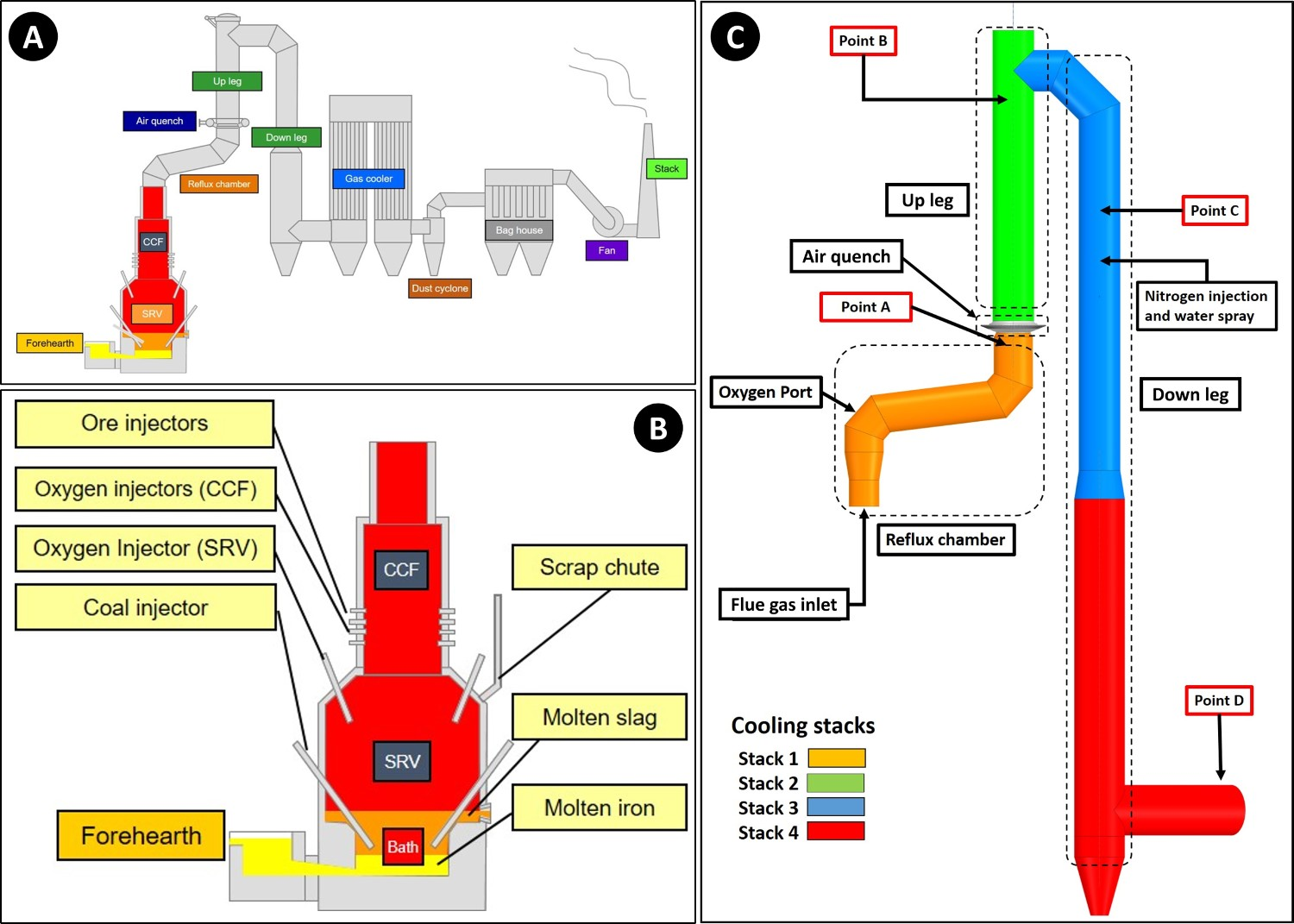
Fine iron ore and oxygen are fed into the CCF through sets of injectors. The iron ore particles are pre-reduced and melted during the fly time inside the CCF and are flung against the wall of the furnace to create a thin liquid film which drips and falls into the molten bath of SRV. The necessary heat for melting and pre-reducing fine ore is coming from partial combustion of the flue gas (containing CO–H2 mixture) coming from SRV, with injected oxygen.
Inside the SRV, pulverized coal is injected into the molten bath through two sets of coal injectors which partially penetrate into the metal bath to carburize the molten iron. Coal particles reduce the pre-reduced iron oxide (FeO x ) droplets fall into the SRV bath from CCF. Carbon monoxide (CO) and Hydrogen (H2) are produced during the reduction processes in the form of bubbles that are ultimately released from the bath to enter the top space of SRV. Pure oxygen is injected through two sets of injectors and partially combusts the gas mixture to provide the necessary heat inside the SRV.
Above CCF, the off-gas system is placed, which consists of four parts namely ‘Reflux Chamber’, ‘Air Quench’, ‘Up Leg’ and ‘Down Leg’ as depicted in Figure 1(C).
The reflux chamber is a slightly angled horizontal pipe with two bends to treat the flue gas coming from CCF. This configuration of the reflux chamber is also called ‘Dog Leg’. It operates at high temperatures to fulfil two important tasks: post-combustion of the remaining CO, H2 and carbon particles from CCF via oxygen injection and also capturing fine molten pre-reduced ore particles escaping the CCF using the described bent geometry. Above the chamber, there is an air quench system, which consists of square channels to inject air to serve two main purposes: cooling the flue gas to reach an appropriate temperature for flue gas cleaning and freezing the molten pre-reduced iron ore particles (escaped from the CCF and reflux chamber) to avoid molten particle accretion on the walls. Further cooling is achieved via nitrogen and water spray injection (evaporative cooling) in the down leg and ultimately flue gas enters the gas cooler (point D) to reach a proper temperature for the bag house and sulphur removal unit.
Zinc recovery from the HIsarna process
Zinc-bearing material can be fed into the process from different sections. For example, materials in the dust form are injected through nozzles into the CCF. On the other hand, granular materials are fed into the SRV through an inclined chute as illustrated in Figure 1(B). The zinc content of the injected material is rapidly evaporated, travels upward and ultimately will end up in the off-gas dust collected by cyclone and bag houses.
During the fourth HIsarna campaign in 2014, a test was performed where dust from the BOS (basic oxygen steelmaking) plant gas cleaning system was injected into the CCF together with iron ore. The dust was mainly made up of iron oxides, but also contained up to 5 wt% Zn. During the tests, it was demonstrated that it is possible to enrich Zn up to 16% into the HIsarna dust, as shown Figure 2. Result of Zn enrichment of the HIsarna flue dust after injection of Zn-containing dust into CCF (data taken from HIsarna plant).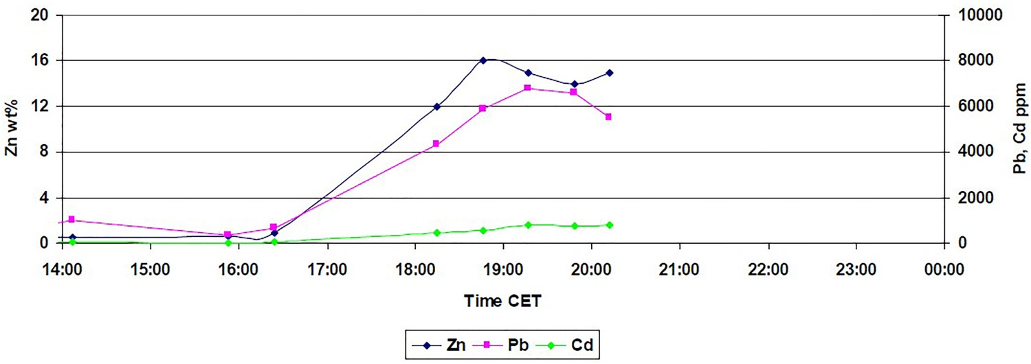
However, during this test, it was only possible to inject a small amount of this dust for a short period of time. This meant that the achieved Zn enrichment was only limited, but it offered the prospect to achieve much higher levels of Zn in the HIsarna off-gas dust without creating a zinc cycle (like in a blast furnace) and detrimental zinc accumulation within the process.
Zinc oxide and zinc ferrite formation
In the HIsarna process, similar to EAF, the Zn vapour content in the flue gas can end up into two main zinc-bearing compounds. It could react directly with oxidants such as O2, CO2 or H2O to form ZnO or react with oxygen and pre-reduced ore (mainly Fe3O4) to form ZnFe2O4 [10–13]. In this context, ZnO is a favourable by-product since Zn recovery from ZnFe2O4, due to its high stability, requires further treatment [2].
There have been numerous studies on the ZnFe2O4 and ZnO formation in iron making industry especially during the EAF process.
Pickles [14,15] have investigated the effect of different parameters on the formation of zinc–manganese ferrite in EAF dust using thermodynamic analysis for the Zn–Fe–Mn–O–H–C system. He has reported that gas composition, mainly high ratio of CO/CO2 and H2/H2O has a significant impact on limiting the formation of both ZnO and ZnFe2O4. Temperature reduction is reported to be a favourable condition for the formation of ferrite. Increasing the amount of Zn and manganese content in the gas can reduce the formation of ferrite, however, an increase in the ferrite formation is reported at high concentration of iron oxide.
Sureerat et al. [16] have investigated the reduction properties of reducing gases (H2-CO mixture) to eliminate and decompose the ZnFe2O4 compound in EAF off-gas over a temperature range of 400–1600°C. Both experimental and thermodynamic analyses were performed. They have reported that ferrite reduction occurs at relatively high temperature and strongly depends on the reducing gas composition. For example, ZnFe2O4 reduction by hydrogen is feasible at a temperature above 1100°C but temperatures above 1500°C are required for reduction by carbon monoxide.
Suetens et al. [10] have performed a detailed experimental study on the formation of ZnFe2O4 in EAF dust to investigate the possibility of in-process separation of Zn from the dust. They have concluded that the ZnFe2O4 formation is thermodynamically favourable in oxygen-rich atmosphere and low temperature same as previously mentioned studies.
Nedar [13] has proposed a gas–solid reaction mechanism for the ferrite formation where the oxygen is reacting with zinc vapour in the presence of liquid iron. The liquid iron is oxidized to form FeO and Fe3O4 and depending on the oxidized form, two different routes are possible. Their proposed mechanism is confirmed by experimental analysis and again points out the importance of oxygen and temperature for the ZnFe2O4 formation. The same mechanism has been investigated by other researchers [10–12].
Learning from the mentioned researches, one can find many similarities between the dust formation in the EAF process and occurring phenomena inside the HIsarna reactor when zinc-bearing material is injected. As will be discussed in coming sections, the off-gas system provides the most favourable environment for the ZnFe2O4 formation. This is due to a high concentration of molten pre-reduced iron oxide particles (Fe3O4), low temperature and high partial pressure of oxygen (or equivalently low partial pressure of carbon monoxide) [10–17].
From the literatures and for the condition inside the HIsarna process, there are few main reactions for ZnFe2O4 and ZnO formation and reduction as listed below:


Figure 3 shows Gibbs energy change versus temperature for reactions (1) to (9). Gibbs energy change versus temperature for possible reactions involving Zn.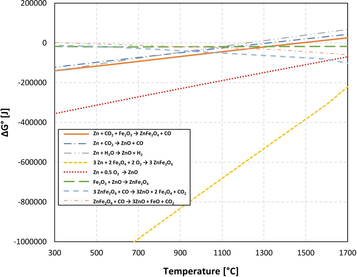
Reaction (4) which is main in the ZnFe2O4 forming reaction [8,9] is highly stable (negative ΔG°) for the defined temperature range, especially at lower temperature. From the same analysis, it can also be seen that the ZnFe2O4 formation reactions are more stable than both ZnFe2O4 reduction and ZnO formation which makes the prevention of the ZnFe2O4 formation quite challenging in the HIsarna process.
Tools and methods
In order to have a detailed analysis on the formation of ZnFe2O4 inside the off-gas system, profiles of temperature, gas composition and molten pre-reduced ore flow rate inside the reflux chamber and the rest of the off-gas system are needed. The temperature values are only available and measured at points A, B and D and the flue gas compositions are only measured at points A and D as shown in Figure 1(C). The molten particle flow rate measurements are quite complex and almost impossible due to a very high temperature and liquid state of particles inside the reflux chamber. These limited measurement points do not provide enough information to have a thorough analysis at every point of the off-gas system.
CFD is a very useful tool to predict the behaviour of the flow in such systems to obtain necessary information regarding gaseous composition, temperature, particle flow rate, etc. A CFD model of the HIsarna off-gas system is setup and validated using plant data in another study by the same authors [18]. Using the developed model, it is possible to obtain all of the profiles, and measure all necessary parameters of the system at any desired points. FactSage thermo-chemical software [19] is used to plot equilibrium diagrams by varying temperature and partial pressure of oxygen to calculate all formed phases. Using the calculated temperature and composition profiles from the validated CFD model, discrete operating points are mapped on the equilibrium graphs to see possible formed phases and compounds inside the off-gas system.
CFD calculation
Detailed discussion on the CFD model setup, mesh, boundary conditions, grid independency and governing equations can be found in the study of Hosseini et al. [18]. In this study, a detailed discussion on the CFD model development is omitted for brevity, however, a quick overview and summary is presented in the following.
Inlet boundary conditions for flue gas, oxygen port and air quench.
CO–H2 and carbon particles are burnt by injecting oxygen inside the reflux chamber and slag particles are captured using the reflux chamber bent forming a flowing liquid layer which runs back into the CCF.
Iron ore is injected with 8 tons h–1 (2.223 kg s–1) into the CCF at the current pilot plant and according to mass balance calculations, on average 10% of the injected iron ore escapes CCF and enters the reflux chamber (0.223 kg s–1). Particle density is considered to be 5000 kg m–3 with a heat capacity of 922 j kg–1 K–1 which are properties of molten Fe3O4 that form majority of the particles. Rosin–Rammler distribution is used to set particle size distribution for the particles with fixed minimum particle size, maximum particle size, mean diameter, spread parameter and number of intervals as 30, 1870, 166 μm, 0.805 and 22, respectively.
To include chemistry/turbulence interaction and calculating reaction rates, the eddy dissipation concept model [20] is considered. The detailed kinetic mechanism proposed by Cuoci et al. [21] is used for CO–H2 mixture combustion.
For carbon particle combustion, field char oxidation model is used which is a simplification of unreacted shrinking core modelling. Kinetic data and expressions proposed by Wen et al. [22] are used for carbon combustion. Water droplet evaporation is also included using the convection/diffusion controlled sub-model.
Particles behaviour (molten ore and carbon) are modelled using the Lagrangian discrete phase method. The trajectory of a discrete phase particles is predicted by integrating the force balance on the particles, which is written in a Lagrangian reference frame. The dispersion of particles due to turbulence in the fluid phase is included using the stochastic tracking model (random walk).
Reflux chamber walls are made of steel tubes and inner side is covered with a refractory of 4 cm. Above the reflux chamber, the walls are only made of steel tubes (OD: 0.038, thickness: 0.005 m). Water flows through the pipes and cools the wall in counter-current flow. All walls are modelled according to the shell conduction approach to consider different material layers. It is assumed that molten particles are at the liquid phase and trapped once they hit the reflux chamber walls (trapped wall boundary condition), but reflected anywhere above the reflux chamber section as they tend to solidify.
CFD results
Figure 4(A) shows the temperature and composition profile along the off-gas system (shown in Figure 1(C)). The length axis refers to the length of a line passing through the middle of the off-gas geometry. The calculated temperature and compositions are averaged on a cross-section sweeping along the length axis. As can be seen, the model predictions (solid lines) are in good agreement with plant measured values (symbols). (A) Calculated gaseous composition and temperature profile and (B) the flow rate of particles across the reflux chamber (dog leg geometry) along the off-gas system.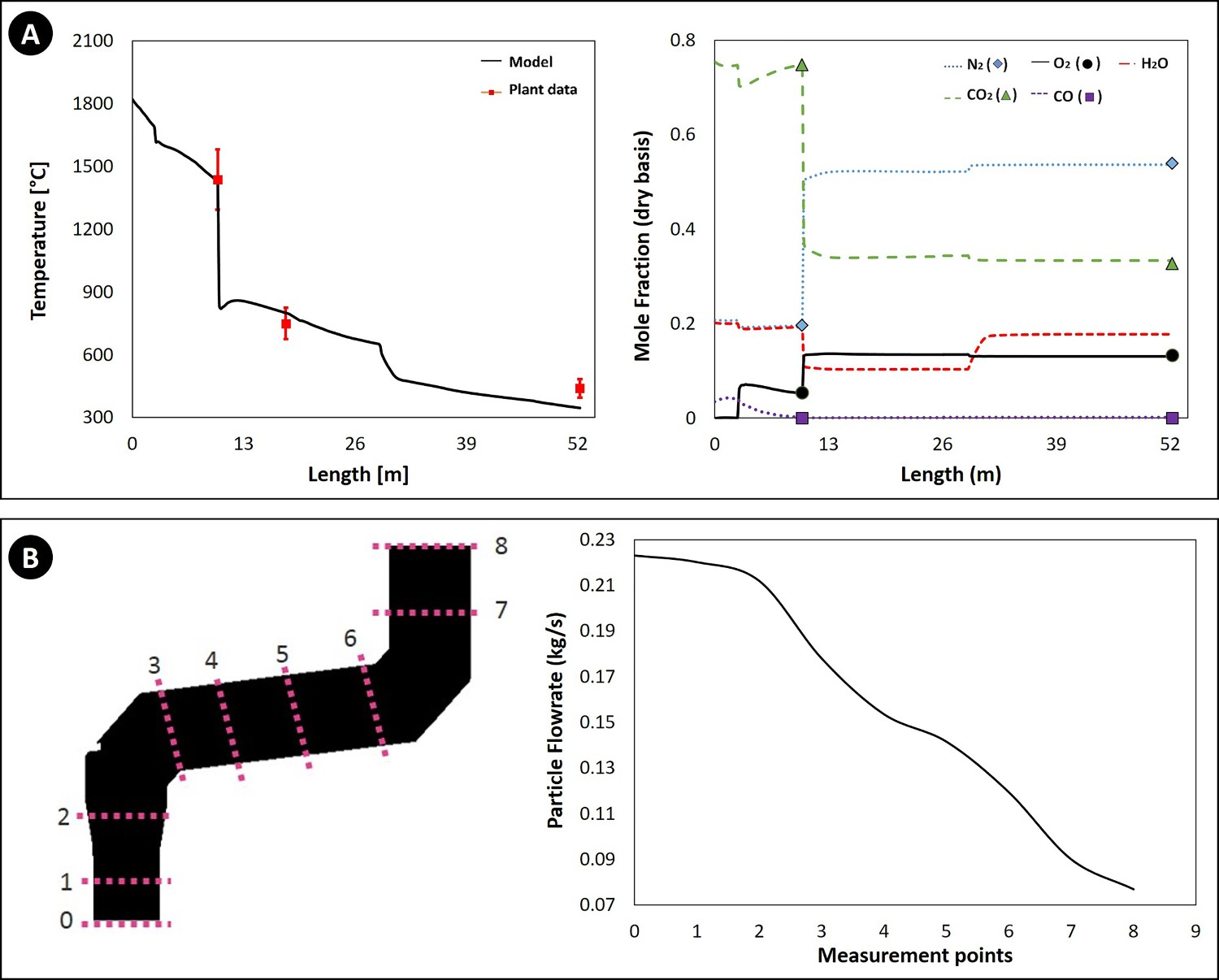
Figure 4(B) illustrates the calculated flow rate of the ore particles across the reflux chamber. The particles are captured by the walls and the flow rate is reduced and after point 8 (reflux chamber outlet) the flue gas and remaining particles enter the air quench section where particles are frozen and no more capturing by walls occurs.
The model for molten particles behaviour is at the initial stage of development and further improvement to consider the effect of particle temperature and state will be presented in another study. However, the predicted outlet flow rate of ore particles is in good agreement with the measured dust flow rate of 0.089 kg s–1 in cyclone and bag houses of the pilot plant. Since the molten particles mainly contain Fe3O4, the reduction in the total particle flow rate means lesser available ingredients for the ZnFe2O4 formation and a potential reduction of ZnFe2O4 content in the collected dust.
FactSage calculation
The atmosphere inside the HIsarna reactor is a reducing environment with high CO and H2 content as shown in Figure 5(A). The mentioned ratio in the figure is from direct measurements and back calculations using the process flowsheet software. As discussed before, the presence of these reducing gases and also high flue gas temperature can significantly limit the formation of both ZnO and ZnFe2O4 [10,14,15]. (A) Gaseous composition and temperature at different outlet sections and (B) total zinc prediction in the spinel phase.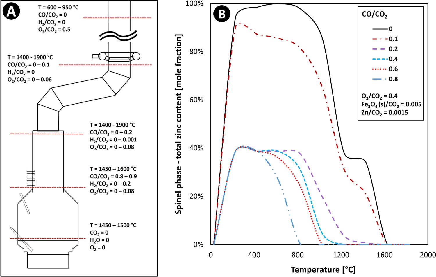
Figure 5(B) shows the effect of temperature on the formation of ZnFe2O4 in a mixture of CO, CO2, H2O, O2, Zn and Fe3O4(s) for different CO/CO2 ratios. The ratios of other gaseous and solid compounds are fixed with respect to CO2. Any Zn content ending up in the spinel phase is in the form of ZnFe2O4 and as can be seen, increasing the ratio of CO/CO2 can considerably reduce the formation of ZnFe2O4, especially at higher temperature. According to this thermodynamic analysis, the formation of ZnFe2O4 at temperature and CO/CO2 range of SRV and CCF is thermodynamically unfavourable. However, at the lower ratio of CO/CO2 which occurs inside the off-gas system, the formation of ferrite at any temperature range is highly appealing.
Furthermore, temperature inside the reflux chamber is quite high, but oxygen injection decreases the local temperature and increases the oxygen partial pressure. The formation of ZnFe2O4 becomes even more favourable with further temperature reduction and oxygen injection above the reflux chamber and in the air quench section.
Altogether the current operating condition of the off-gas system makes this part of the process the region of interest for this study as it exhibits higher potential of the ZnFe2O4 formation compared to the rest of the HIsarna reactor. From Figure 5(B), it can also be concluded that most of the Zn content will stay if the form of vapour at the inlet of the off-gas system.
‘Phase Diagram Module’ of FactSage software is used to plot the equilibrium graph (oxidation graph) using the listed compounds in Table 2. Figure 6 shows an example of a plotted graph. Equilibrium graph with mapped operating points for R = 0.01. Components used to plot equilibrium graphs in FactSage software.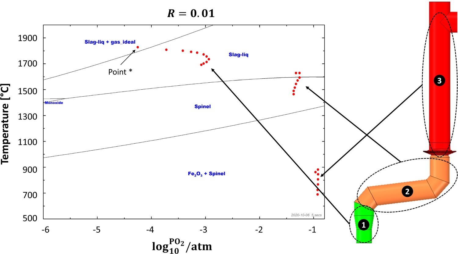
Equilibrium graphs are based on the temperature and 

For all calculations, the molar ratio of Zn vapour to iron oxide 
The equilibrium graphs are divided into different regions separated by solid lines. Each region might contain one or a combination of phases. Possible formed phases are ‘Ideal gas’, ‘Liquid slag’ (slag-liq), ‘Spinel’, ‘Monoxide’ (slag in solid form) and ‘Fe2O3’. Another possible phase is ‘Zincite’ which is formed at a very high ‘R’ ratio (when zinc vapour content is high in flue gas) as shown in later figures.
Possible phases and components inside each phase.
Figure 6 also contains operating points (red dots) for different sections of the off-gas system. Those operating points are discrete points along the reflux chamber and up leg (up to point B in Figure 1(C)) with calculated temperature and partial pressure from the discussed validated CFD model. For instance, point * refers to the reflux chamber inlet with temperature of 1812°C and almost zero oxygen partial pressure 
Using the equilibrium graphs with mapped operating pints, it is possible to observe where those operating points fall and which phases might form in the presence of a certain ratio of zinc vapour and iron oxide. For example in Figure 6, the operating points in the first section of the reflux chamber (before oxygen injection), fall into the ‘Slag-liq + Ideal gas’ region where zinc elements speciate into the slag in the form of ZnO or remains in gaseous form due to high temperature and absence or existence of minor oxygen. In the second section, the partial pressure of oxygen is sharply increased and temperature drops locally. This is a favourable condition for the ZnFe2O4 formation and as it can be seen most of the operating points fall into the ‘Spinel’ phase where the major component is Fe3O4 and all of the zinc element speciate into ZnFe2O4. The same situation can be seen in the third section where the major phase is ‘Fe2O3’ and ‘Spinel’.
Results and discussion
Current pilot scale – dog leg geometry
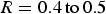
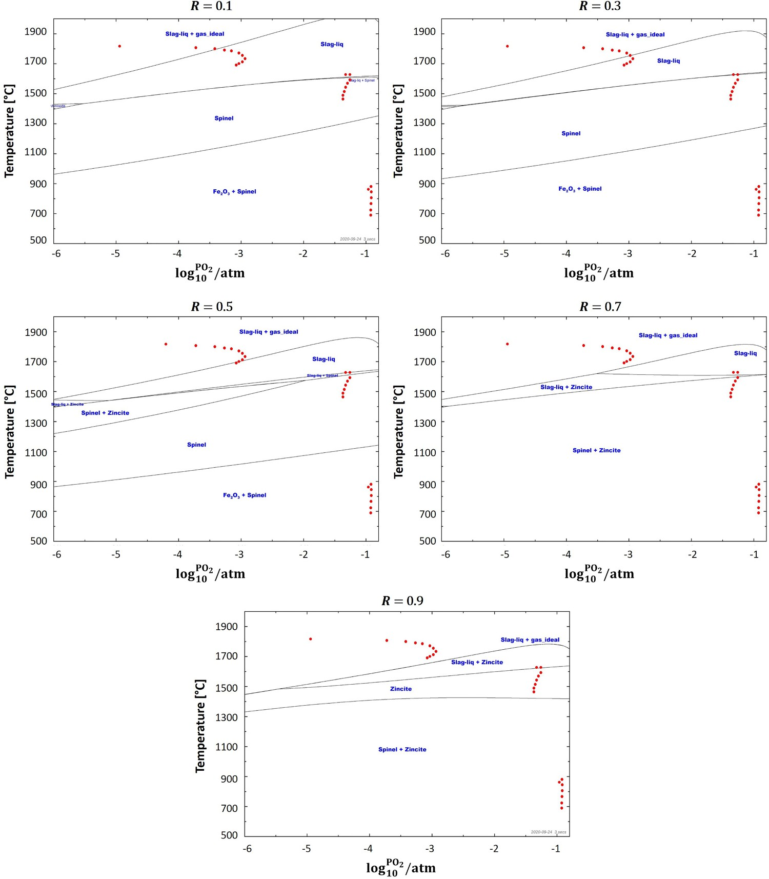
Figure 7 depicts equilibrium graph with mapped operating points for different ‘R’ ratios. As can be seen, at the lowest investigated ratio where Equilibrium graph with mapped operating points for ‘dog leg’ geometry and for different ‘R’ values. Laboratory analysis of HIsarna baghouse dust for Zincite (ZnO) and Zinc ferrite (ZnFe2O4) fraction.

Reflux chamber geometrical modification
From previous discussion and calculations, the impact of temperature and oxygen partial pressure on the formation of ZnO and ZnFe2O4 became evident. The main focus will be on geometrical and operational modification of the reflux chamber since, according to equilibrium graphs, this section of the off-gas system can still offer possibilities to minimize the formation of ZnFe2O4. To maximize the formation of ZnO-containing phases, high temperatures and lower partial pressures of oxygen (or high partial pressure of CO) are required inside the reflux chamber.
Considering a fixed condition at the inlet of the chamber, the following solutions are available to practice: One solution is to increase the ‘R’ ratio as discussed in study of Pickles [14,15] and based on the thermodynamic calculations in section ‘Reflux chamber geometrical modification’. This can be achieved through increasing zinc content inside the off-gas system by injecting more zinc-bearing material into the process. With this solution it is possible to increase the ratio to a certain extent as injecting very high amount of zinc-bearing material is complex and might cause technical issues. For example, injecting galvanized scrap particles in large quantities into the SRV molten liquid could cause local liquid freezing which is detrimental to the steady operation of the plant. It is also possible to increase the ‘R’ ratio by increasing particle capturing inside the reflux chamber to limit the availability of Fe3O4, especially in those regions with high oxygen partial pressure and low temperature. It is also possible to modify the geometry of the reflux chamber to provide larger region with high temperature and low partial pressure of O2 or keeping CO partial pressure as high as possible before the post-combustion (creating a reducing environment). The presence of CO in the flue gas will limit the formation reaction of ZnFe2O4.
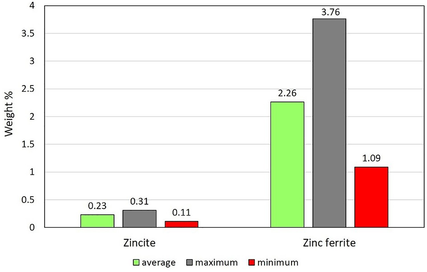
To fulfil these goals, a modified reflux chamber geometry shown in Figure 9 is proposed. This geometry will be called ‘Frog Leg’ from now on and as can be seen, the second bend is added to the original geometry (Dog Leg) and the oxygen port is shifted upward to delay the post-combustion. Proposed modification to the reflux chamber, frog leg configuration.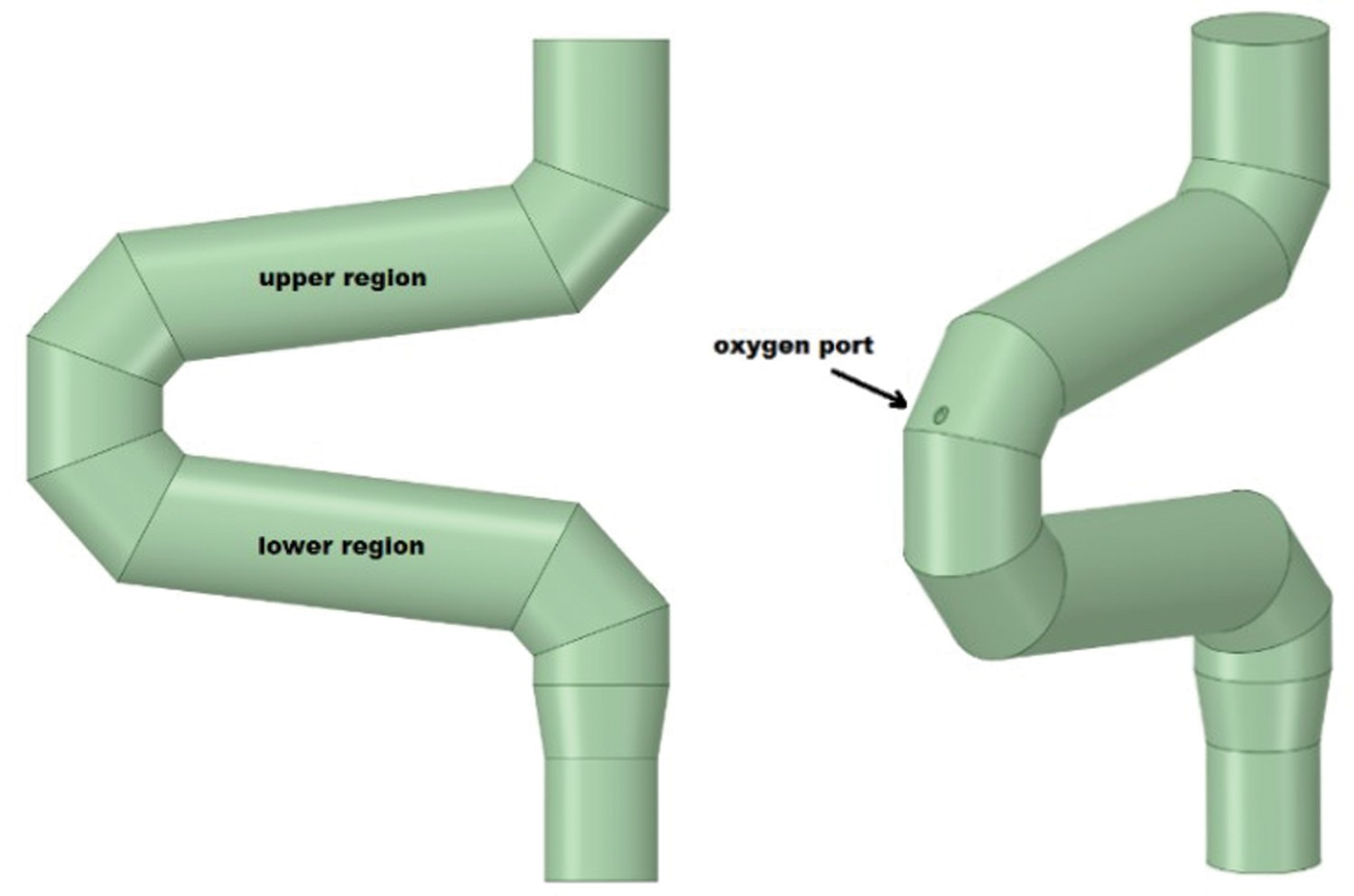
The same discussed CFD model is used to determine temperature profile, compositional change and particle flow rate along frog leg geometry and results are illustrated in Figure 10. (A) Predicted gaseous composition and temperature profile along frog leg and air quench (obtained from CFD calculations up to point C) and (B) predicted flow rate of particles across the frog leg geometry.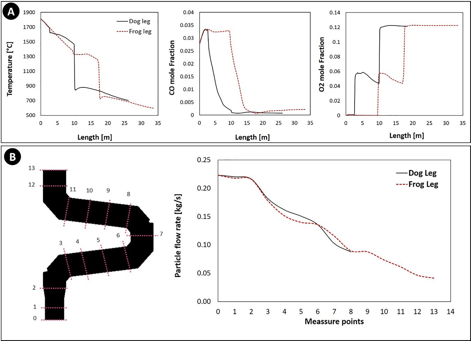
In dog leg geometry, the temperature falls drastically at the length of 10 m, whereas for frog leg, this drastic reduction happens at length of 18 m, providing extra 8 m length for the flue gas to stay at high temperature. Also from the same figure, it can be seen that oxygen injection and CO combustion are delayed for 8 m which is again beneficial to prevent the ZnFe2O4 formation and promoting the ZnO formation.
Once ZnO is formed inside the slag, it will be stable and in the form of small distinguished particles. This is confirmed by study of Suetens et al. [10] that reported the presence of ZnO particles inside the collected dust from EAF via EDS mapping (Energy Dispersive Spectroscopy).
The only way to destabilize and reduce the formed ZnO is through gaseous reduction or solid state reaction. The solid state reaction is quite slow and highly controlled by kinetics thus is unlikely to happen within the available short resident time inside the off-gas system. The possibility of ZnO reduction by reducing gases are also limited, because for the gas–solid reaction, the gaseous compound must diffuse into the solid surface which is again unlikely as the partial pressure of the CO–H2 mixture is very low inside the off-gas system.
It also worth mentioning that according to thermodynamic calculations (Gibbs free energy) and study of Sureerat et al. [16], the reduction of both ZnO and ZnFe2O4 can proceed only at high temperature and highly reducing environment. Thus, a stable ZnO content in hot zones and also cooling path (above reflux chamber) can be expected.
The other benefit of this modification is that the content of molten pre-reduced particles is constantly decreased as depicted in Figure 10(B). In dog leg geometry, the flow rate of particles entering the oxygen injection area is around 0.182 kg s–1 however, for frog leg geometry the flow near oxygen injection is 0.089 kg s–1. This means an increase in ‘R’ ratio from 0.2 to 0.4 in oxygen-rich region which can limit the formation of ZnFe2O4 inside the reflux chamber.
These conclusions can be quantified with the same FactSage analysis to investigate possible ZnFe2O4 forming spots inside the frog leg. The results are reported in Figure 11 and as can be seen, compared to the dog leg geometry, higher number of operating points in the first section of the frog leg falls into the liquid ‘Slag’ phase. However, the formation of spinel is still inevitable due to the temperature reduction in oxygen and air injection regions. The operating points shift upward by increasing the ‘R’ ratio and the formation of spinel (and ZnFe2O4) will be limited in the same way discussed for the dog leg geometry. Equilibrium graph with mapped operating points for ‘frog leg’ geometry and for different R values.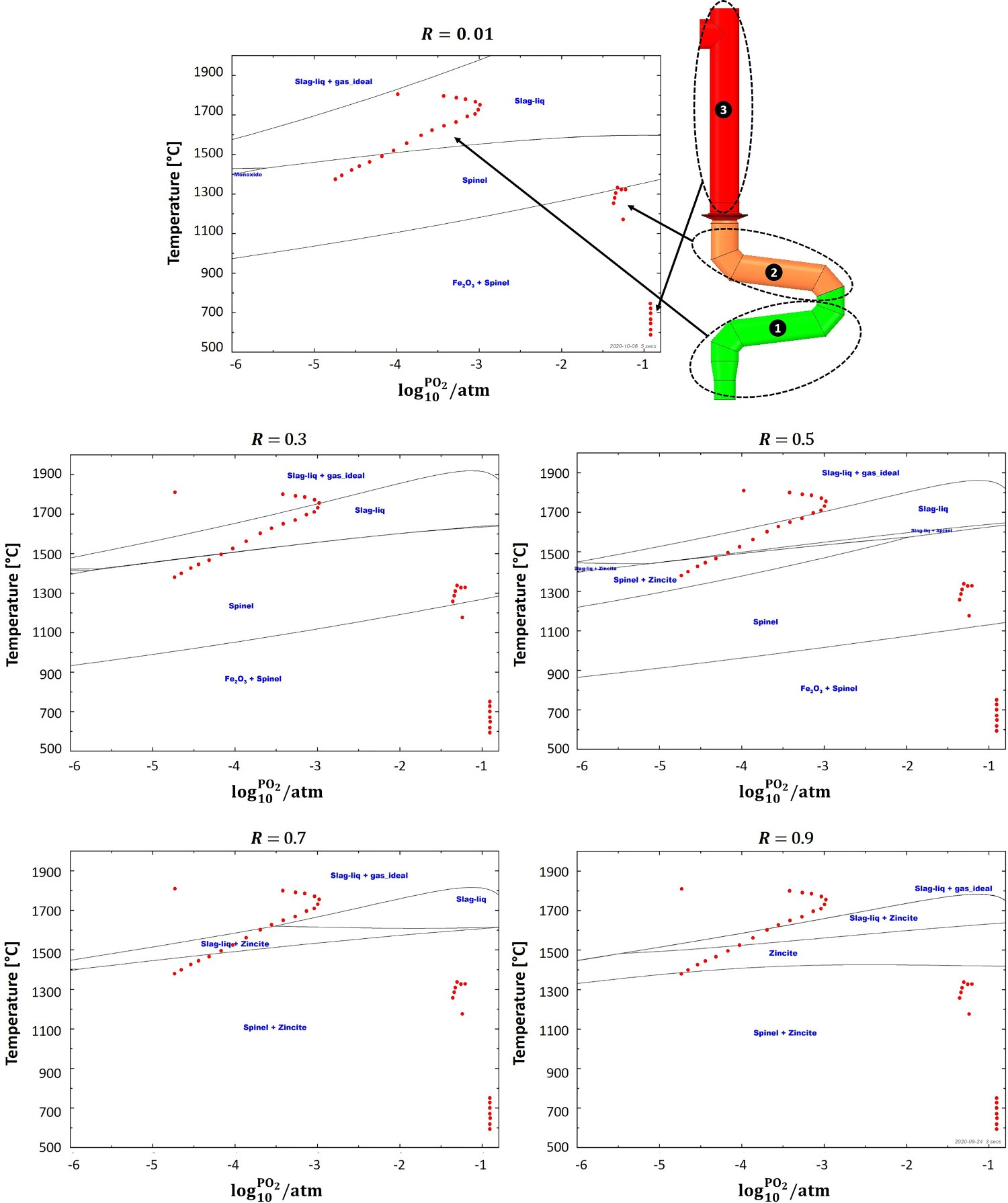
The geometrical modification can also positively contribute to the combustion and removal of other undesired compounds such as carbon particles and CO–H2 mixture inside the off-gas system which has been investigated in another study by the same authors [23].
In conclusion, based on the analysis so far, for any reflux chamber configuration (dog leg or frog leg), the most efficient way to increase ZnO content of the collected dust would be increasing the ‘R’ ratio by injecting higher amount of zinc-bearing material. Steel scrap injection into the molten slag would be an interesting option as it’s a very efficient way to recover the iron content of the scrap and to reduce the consumption of iron ore. However, when it comes to zinc recovery, it has shortcomings. Achieving the high ‘R’ ratio requires a considerable amount of steel scrap injection which can reduce the slag temperature and might cause the disturbance in temperature control and local freezing.
So it is suggested to inject zinc-bearing material not only in the form of the steel scrap injection into the molten slag, but also through other forms and from other section of the process such as zinc-bearing dust injection into the CCF or SRV upper section. This way the Zn content along the off-gas system is evenly distributed and local disturbances are recovered faster.
Reflux chamber wall modification
In order to make sure that operating points inside the first section of the frog leg geometry stay away from the ‘Spinel’ region for minimum and maximum ‘R’ ratio, a further modification might be required. Considering the modified geometry, the only feasible way is to keep the temperature as high as possible inside the chamber. This can be achieved by either increasing refractory wall thickness to reduce the heat losses through the walls or increasing CO content at the inlet of the off-gas system to provide more fuel for post combustion. The validated CFD model is used to investigate both solutions. Figure 12(A) shows the temperature profile for different refractory wall thicknesses of the reflux chamber. For a fixed equilibrium graph, the operating points shift upward by increasing the flue gas temperature as depicted in Figure 12(B) for maximum and minimum considering the ‘R’ ratio. This shift will locate the operating points of the first section in more favourable equilibrium region where zinc element remains either in gaseous form or speciate into the slag in form of ZnO. It worth noting that even at high temperature, the formation of ‘Spinel’ and ZnFe2O4 is still inevitable once the oxygen becomes available (upper region of frog leg). So practically this geometrical modification could minimize the ZnFe2O4 to a certain extent and may not fully prevent the undesired product formation. (A) Calculated temperature profile for the off-gas system with frog leg geometry for different wall thicknesses (up to the point C) and (B) equilibrium graph with mapped operating points for frog leg geometry.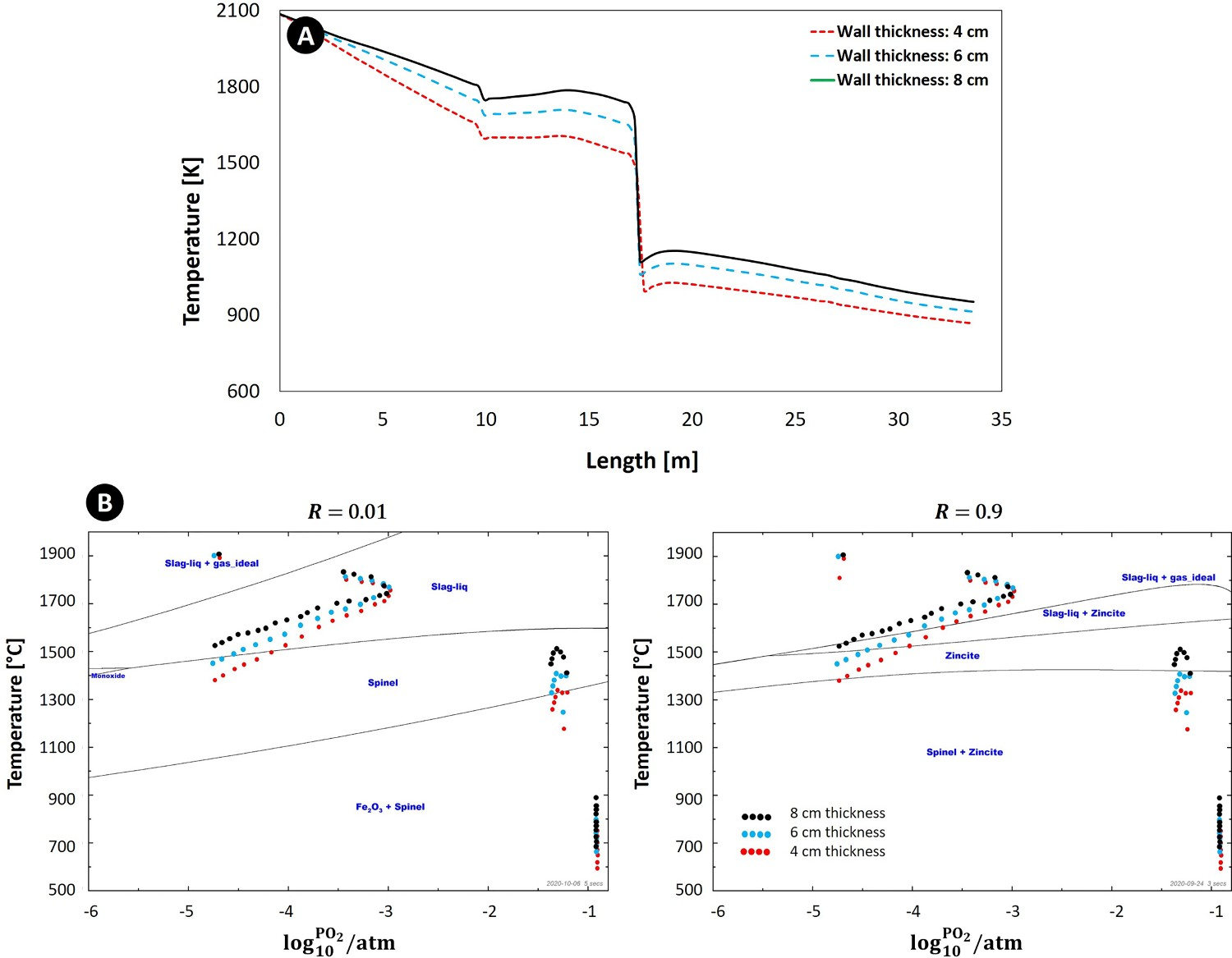
Increasing CO content inside the reflux chamber
Due to the harsh condition inside the reflux chamber, the refractory wall is exposed to thermo-chemical stresses which can cause wall material loss and thickness reduction. To make the wall thickness solution work fine, it is required to refresh the refractory wall on a regular basis which might not be feasible during long runs. Therefore, more feasible solution would be increasing the CO content of the flue gas at the inlet of the reflux chamber by reducing the CCF post-combustion ratio. Since the HIsarna process has a transient nature, in real plant operation the amount of CO at the inlet of the off-gas system can reach up to 10% (molar fraction).
Figure 13 shows the effect of CO content on flue gas temperature and oxygen composition along with the operating point position on the equilibrium graph for both dog and frog leg geometry. As can be seen, by increasing CO content at the inlet, most of the operating point will be shifted upward and into regions where Zn vapour speciates into ZnO even in the second section, where post combustion oxygen is injected in considerable amount. Effect of CO content on temperature, oxygen profile and operating point for dog leg and frog leg geometry and for lowest and highest ‘R’ ratios.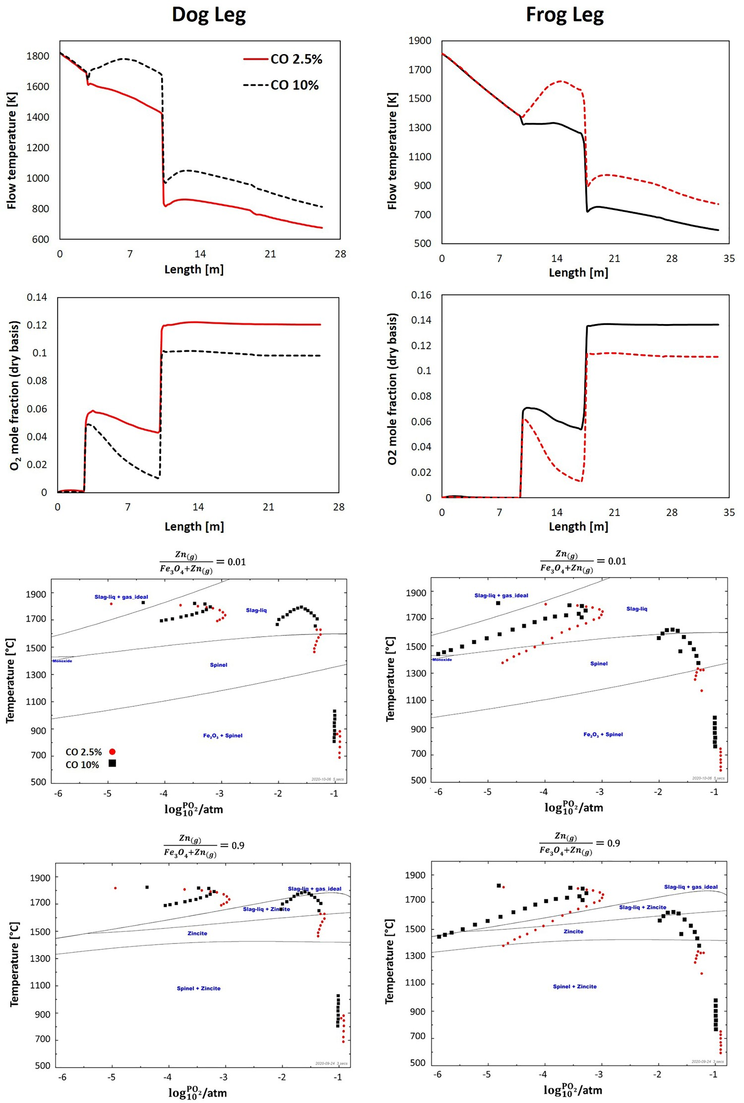
Keeping CO partial pressure high inside the reflux chamber offers several benefits. Higher CO content means higher fuel for the post -combustion process which in turn signifies higher heat release and temperature profile to limit the evolution of ZnFe2O4 similar to the effect of wall thickness. As mentioned earlier, with higher temperature, the operating points on the equilibrium graph are shifted upward to the regions with favourable form of Zn element. Moreover, high CO content consumes oxygen across the reflux chamber and lowers its partial pressure to create a reducing environment where CO/CO2 ratio is high. The higher is the CO/CO2 ratio, the lower would be the risk of ZnFe2O4 formation (see Figure 5).
Conclusion
A thermodynamic analysis of ZnFe2O4 and ZnO formation inside the off-gas system of the HIsarna process is performed. The aim is to avoid or minimize the formation of ZnFe2O4 compound as it is an undesired by-product of Zn vapour reaction with iron oxide.
Since limited measure points from the real plant data were available, a CFD model was developed and validated to describe the composition and temperature profile variation inside the off-gas system.
The analysis was performed using equilibrium graphs and mapped operating point obtained from CFD calculations. It was found that the most favourable conditions for the ZnFe2O4 formation are high oxygen partial pressure, high content of pre-reduced iron ore (high Fe3O4 content) and low temperature which are in agreement with other experimental and numerical studies.
These conditions are met at the current state of the plant operation and according to thermodynamic analysis, the off-gas system have higher ZnFe2O4 formation potential compared to SRV and CCF sections. Inside the SRV and CCF, the formation of ZnFe2O4 is limited due to highly reducing environment. On the other hand, in the off-gas system, the environment is highly oxidizing owing to the injection of post combustion oxygen and air. Since the oxidizer are injected at a very low temperature (20–30°C), it will also cause a rapid temperature drop across the off-gas system which again highly contributes to the formation of ZnFe2O4.
Among the proposed solutions, the easiest way was to increase the zinc to iron oxide molar ratio (‘R’ ratio) which will shift the mapped operating points into the phasic regions with ZnO compound as the final product of Zn vapour reactions. However, achieving a high ‘R’ ratio is challenging and the formation of ZnFe2O4, even at the highest ‘R’ ratio, is still predicted inside the off-gas system.
For further reduction of ZnFe2O4 formation, a geometrical modification of the reflux chamber is proposed by adding another turn to the current design. The same analysis was performed for modified geometry and it was shown that the area with low oxygen content and high temperature is expanded which provides more residence time for Zn element to speciate into the desired phases with ZnO content.
The proposed modification can lead to a higher capturing efficiency of molten pre-reduced particles by the walls. This inherently can reduce the Fe3O4 content of the flue gas and increase the ‘R’ ratio which limits the formation of ZnFe2O4.
Nevertheless, the proposed modifications can only minimize the formation of undesired products to a certain extent and not fully eliminate it. The formation of ZnFe2O4 is still inevitable as some of the operating point, especially those points near the oxygen and air injection still fall into the spinel-containing zones where Zn vapour will speciate into the ZnFe2O4 compound in reaction with oxygen and iron oxide at low temperature.