
Abstract
The effects of the difference of the heat flux between the wide face and narrow face of the mould, the mould taper, casting speed and cooling rate on unevenness of hypo-peritectic steel at the off-corner in the mould, which leads to longitudinal cracking, bleeding and breakout during continuous casting, were evaluated by a finite element model (FEM) simulation and a plant test with a commercial continuous caster. The simulation results show that an increase in the difference in the heat flux between the wide and narrow face increases the off-corner unevenness of solidification because the solidified shell on the low heat flux side is pulled toward the high heat flux side. The analysis results were in good agreement with the plant test results. These results revealed the importance of optimizing the heat flux ratio between the wide face and narrow face mould even under a high casting speed condition.
Introduction
In recent years, both high slab quality and high productivity have been required in continuous casting. Surface cracking of slabs during continuous casting is a serious problem. In particular, longitudinal cracks on the slab surface cause not only slab quality deterioration during high-speed casting, but also operational trouble such as bleeding and breakout [1–4]. It has been reported that slab longitudinal cracking occurs in hypo-peritectic steel (C = 0.09–0.17 wt-%) due to deflection of the solidified shell during the δ to γ transformation in the initial stage of solidification in the mould [5–11]. One of the primary uses of mould flux is to prevent uneven solidification and longitudinal cracking by stabilizing the heat transfer between the solidified shell and the mould [12–14]. It is also known that not only uneven solidification but also the air gap between the shell and the mould greatly affect the growth of the solidified shell and uneven solidification in the vicinity of the corner, leading to longitudinal cracking and bleeding in the vicinity of the slab corner. Since the mould taper value greatly affects shell growth and uneven solidification, the mould taper values of the wide side and narrow side need to be optimized corresponding to solidification shrinkage [15,16]. In order to minimize air gap formation between the solidified shell and the mould, which is more important in high-speed casting, a multi-tapered mould has been developed for the narrow side mould [17]. Kim et al. [18] reported that the difference in the heat flux between the wide side mould and the narrow side mould, as well as the mould taper, affected the unevenness of the solidified shell with complex solidified shell deformation in the vicinity of the corners, leading to longitudinal cracking, bleeding as shown in Figure 1. In high-speed casting, the unbalanced flow in the mould, the heat flux in the mould, and the variation of heat flux in the mould width direction become large [19,20], and the heat flux difference between the wide side mould and the narrow side mould also becomes large, which can result in further deterioration of the unevenness of solidification near the mould corner. However, there have been few reports on the influence of the difference of the heat flux of the wide side mould and the narrow side mould on the air gap between the solidified shell and the mould and the solidification behaviour in the vicinity of the corner. Therefore, in this study, a FEM analysis and experiment in the continuous casting machine were carried out in order to evaluate the effects of the heat flux difference between the wide side and narrow side of the mould, the taper value of the mould, the casting speed, and the cooling rate of the solidified shell in the mould on the air gap formation, the solidified shell deformation behaviour and the unevenness in the solidified shell near the corner in the mould during continuous casting. Example of solidified shell structure near corner in mould where severe crack and bleeding occurred [18].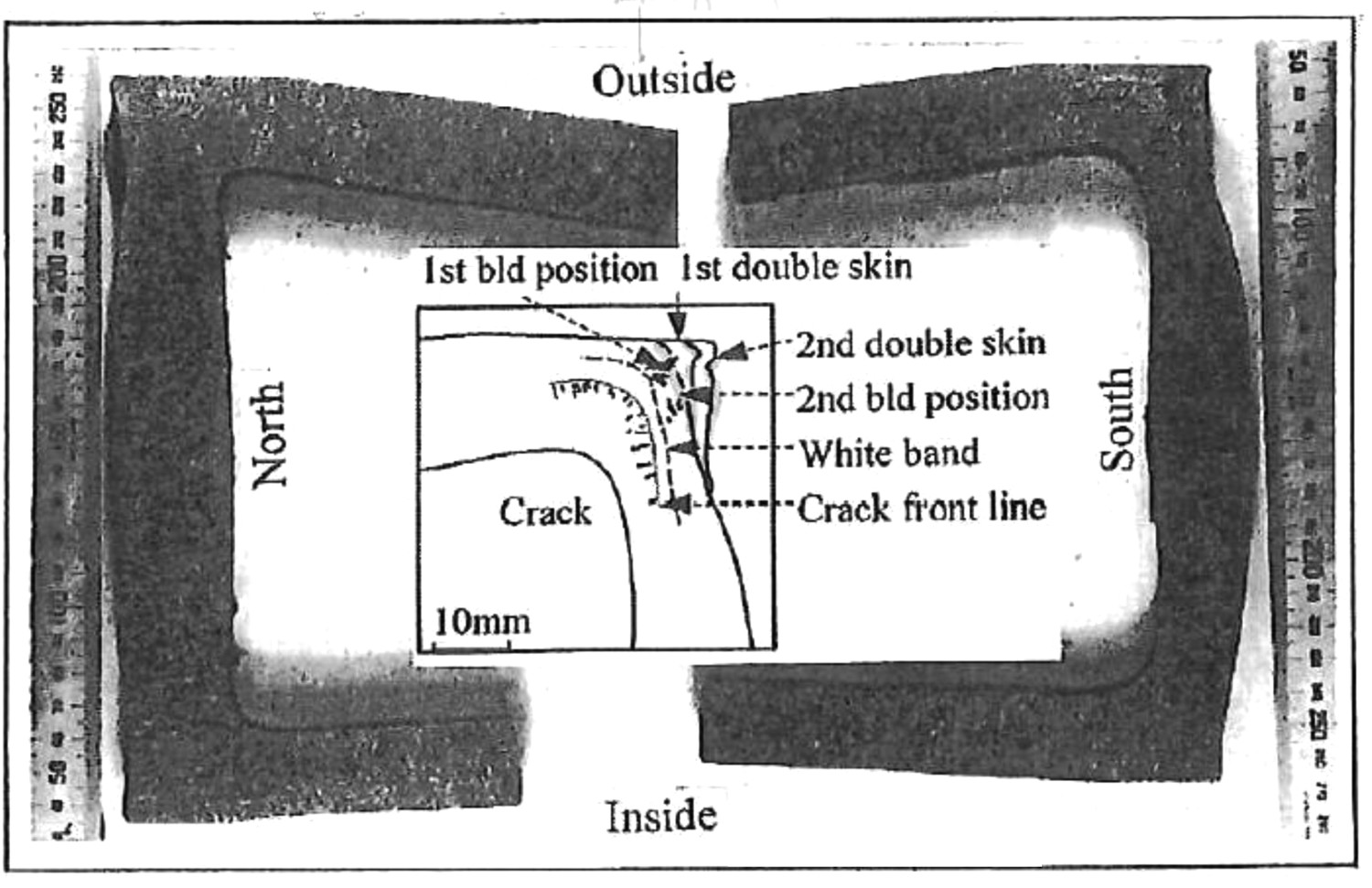
Mathematical model
The heat transfer calculation and the calculation of the solidified shell deformation in the mould were carried out for a Fe-0.1 wt-% C hypo-peritectic steel with the commercial FE package ABAQUS. Figure 2 shows schematic illustrations of the heat transfer and solidified shell deformation models. The calculations were performed on a two-dimensional quarter cross-section of a slab 252 mm in thickness and 1000 mm in width with a regular square mesh [21]. Schematic illustration of (a) heat transfer model and (b) solidified shell deformation model in the mould.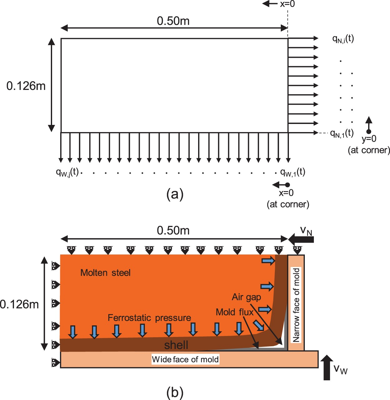
Heat transfer model
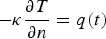
The temperature distribution in the solidified shell shown in Figure 2(a) was calculated by two-dimensional unsteady state heat transfer conduction by a heat transfer equation and a heat transfer boundary condition, i.e.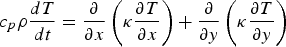


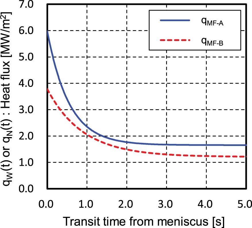
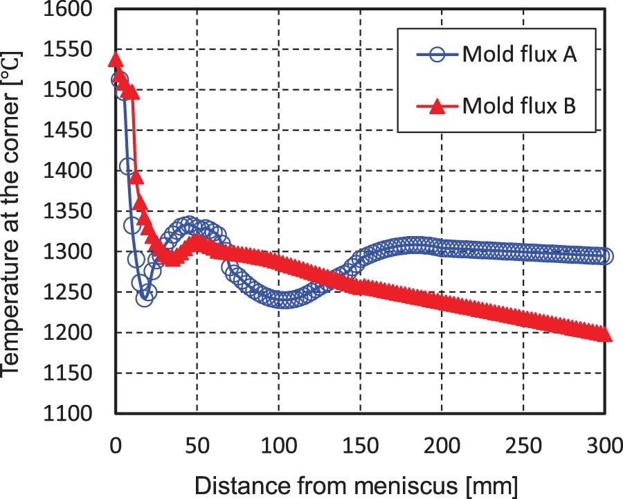
The latent heat (ΔH [272.1 J g–1] [23]) effect is considered by the apparent heat capacity method given by Heat flux as a function of transit time from the meniscus for mould flux A and mould flux B [11].

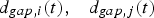


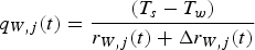
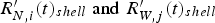
The average mould flux film thickness used in this study was calculated based on the relationship between the casting speed and the consumption of mould flux A and mould flux B, respectively, as reported by Kanazawa et al. [2] In this calculation, the solidified shell, air gap, mould flux film, and mould are considered as the heat transfer resistance in the mould [11]. The expressions for the heat flux of the narrow side and wide side moulds are shown in Equations (5) and (6).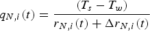
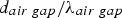
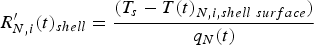
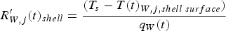
The thermal resistance 


Further, the thermal resistance 


Thermophysical properties of steel used in the heat-transfer model.
Mechanical model of solidified shell deformation
A shell deformation static analysis of the two-dimensional cross section shown in Figure 2(b) was performed under the same conditions as the width, thickness, mesh size, and number of meshes used in the heat transfer calculation. A pressure P (Pa) is applied at the boundary between the liquid and the solidified shell corresponding to the ferrostatic pressure, as expressed by Equation (12).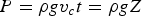

The elastic modulus was based on the experimental data of Mizukami et al. [27] was used, and Poisson's ratio was assumed to be 0.3. In the experiment by Mizukami et al. [27], the elastic modulus of Fe–0.08%C–0.19%Si–0.66%Mn–0.019%P was measured. This composition can be regarded as hypo-peritectic steel from the equivalent carbon content (Ceq = 0.10 wt-%), considering the effects of the various elements proposed by Xu et al. [28] to predict if a steel exhibits peritectic behaviour.
The strain rate dependent plasticity constitutive equation expressed by Equation (13) was used to predict the temperature and strain-rate dependence on flow stress [29]. Flowchart of calculation procedure.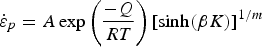


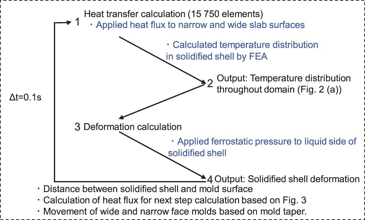
Note that friction between the solidified shell and the mould was neglected in this model for simplicity. The heat flux was calculated considering the size of the gap between the solidified shell and the mould obtained from the solidified shell static deformation calculation expressed by Equations (5) to (10), and the result was used as the heat flux for the next step of the heat transfer calculation. The calculation was carried out under the conditions that the time step of the calculation was 0.1 s, the length from the meniscus to the bottom of the mould was 800 mm, and the casting speed (Vc ) was 1.5, 3.0, or 5.0 (m min–1).
Further, this model also considers the effect of the cooling rate on the density and thermal expansion resulting from the 


The key assumptions of the model are that undercooling below the peritectic temperature is negligible, carbon diffusion is controlling for the growth of the 


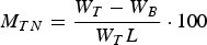
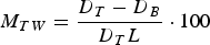
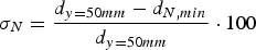
In this calculation and the experiment, the unevenness near the corner of the narrow side (


Experimental method


Casting conditions.
Furthermore, a comparison with and without longitudinal cracks caused by uneven solidification in the vicinity of the mould corner was also carried out. R was obtained by calculating the heat fluxes in the mould [36] from the results of temperature measurements 50 mm below the meniscus using thermocouples embedded in the centre of the width of the wide side mould and the centre of the thickness of the narrow side mould.
Results and discussion
Effect of narrow side mould taper
In the present heat transfer calculation, as described above, the calculations were carried out under the condition that both the mould flux and an air gap can coexist between the mould and the solidified shell. Figure 5 shows the result of a preliminary evaluation of the effect of the heat transfer in the gap between the mould and the solidified shell on the unevenness of the solidified shell near the mould corner. Three cases were evaluated: existence of only the air gap, existence of only the mould flux as determined from the consumption of mould flux, and coexistence of the air gap and the mould flux in the gap part. The figure shows the unevenness near the corner of the narrow side mould in solidification (
σN
as a function of distance from the meniscus with only an air gap, air gap + mould flux, and only mould flux (mould flux A, MTW
= 0%/m, MTN
= 1.1%/m, V
c = 1.5 m min–1, R = 1.0). Deformed geometries of solidified shell and air gap at (a) 100 mm, (b) 300 mm,(c) 500 mm, and (d) 800 mm from meniscus (mould flux A, MTW
= 0%/m, MTN
= 1.1%/m, V
c = 1.5 m min–1, R = 1.0).


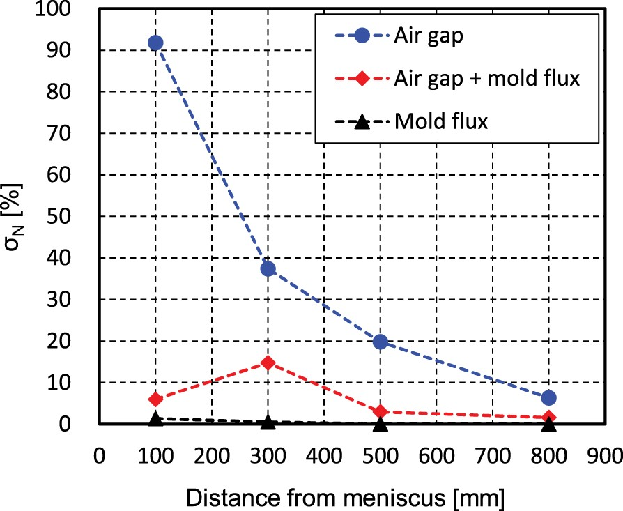
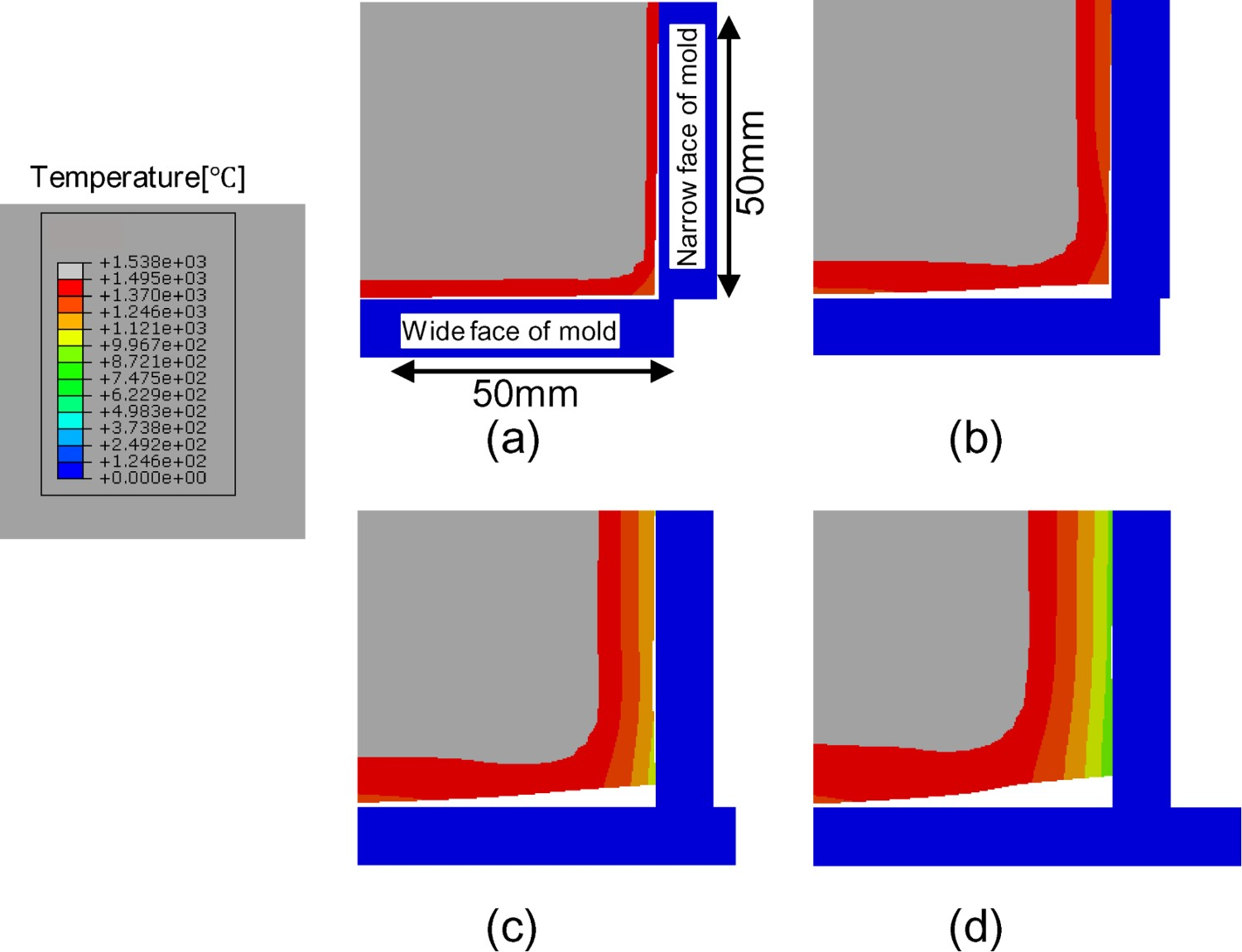


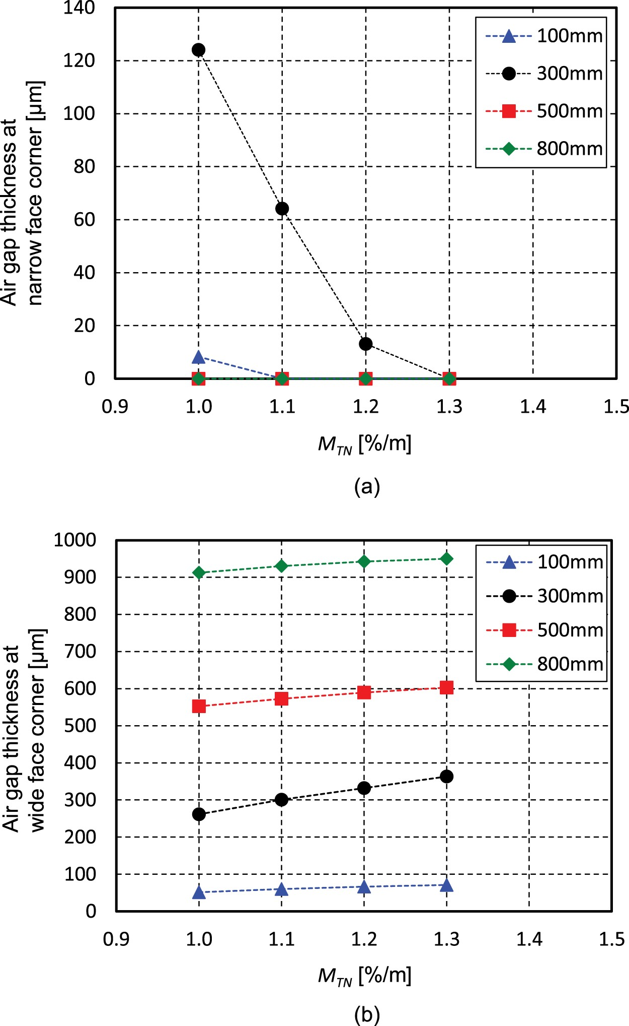
Figure 8 shows the relationship between the narrow side mould taper MTN
and the air gap thickness between the corner solidified shell and the narrow side mould (a) or the wide side mould (b) in the case of mould flux A, MTW
= 0%/m, Vc
= 1.5 m min–1, and R = 1.0. When MTN
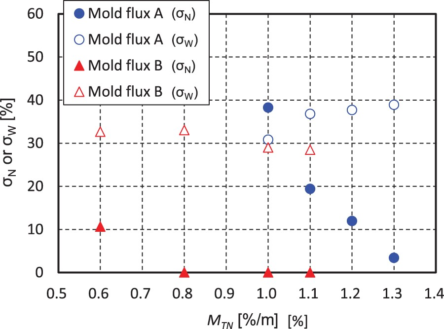
decreases, the air gap thickness on the narrow side mould becomes larger, and the air gap on the wide side mould becomes smaller. Thus, the taper on the narrow side mould affects not only the narrow side mould but also the air gap thickness on the wide side mould. Figure 9 shows the effect of the mould flux on the relationship between MTW
and Air gap thickness at (a) narrow face corner and (b) wide face corner as a function of the mould taper of the narrow face (mould flux A, MTW
= 0%, Vc
= 1.5 m min–1, R = 1.0). Influence of mould taper of the narrow face on σN
and σW
300 mm from the meniscus with mould flux A and mould flux B (MTW
= 0%, Vc
= 1.5 m min–1, R = 1.0).


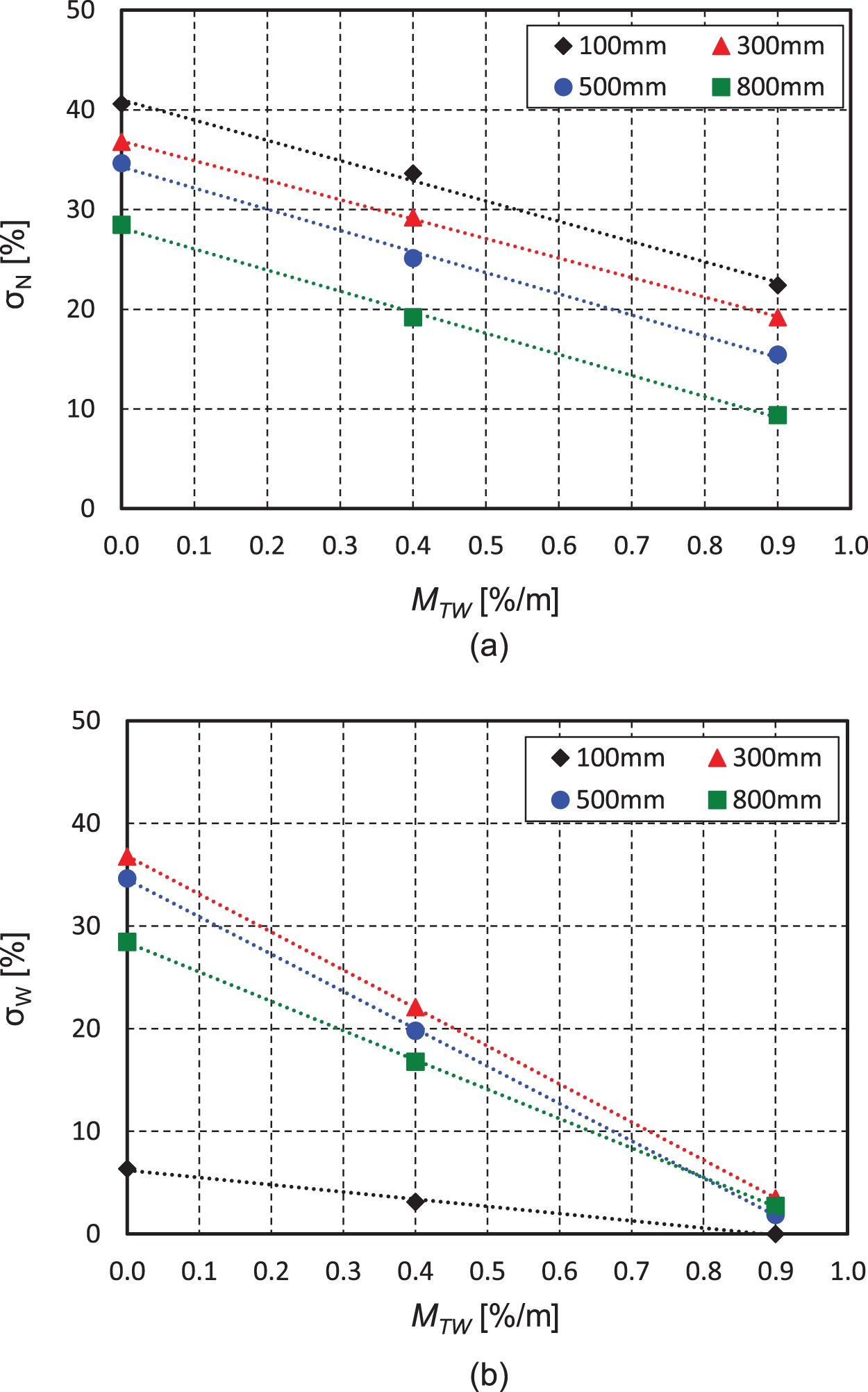
Effect of wide side mould taper
Figure 10 shows the relationship between the wide side taper and Influence of mould taper of the wide face on (a) σN
and (b) σW
at 100, 300, 500, and 800 mm from the meniscus (mould flux A, MTN
= 1.1%/m, Vc
= 1.5 m min–1, R = 1.0).


Effect of heat flux difference between wide and narrow sides
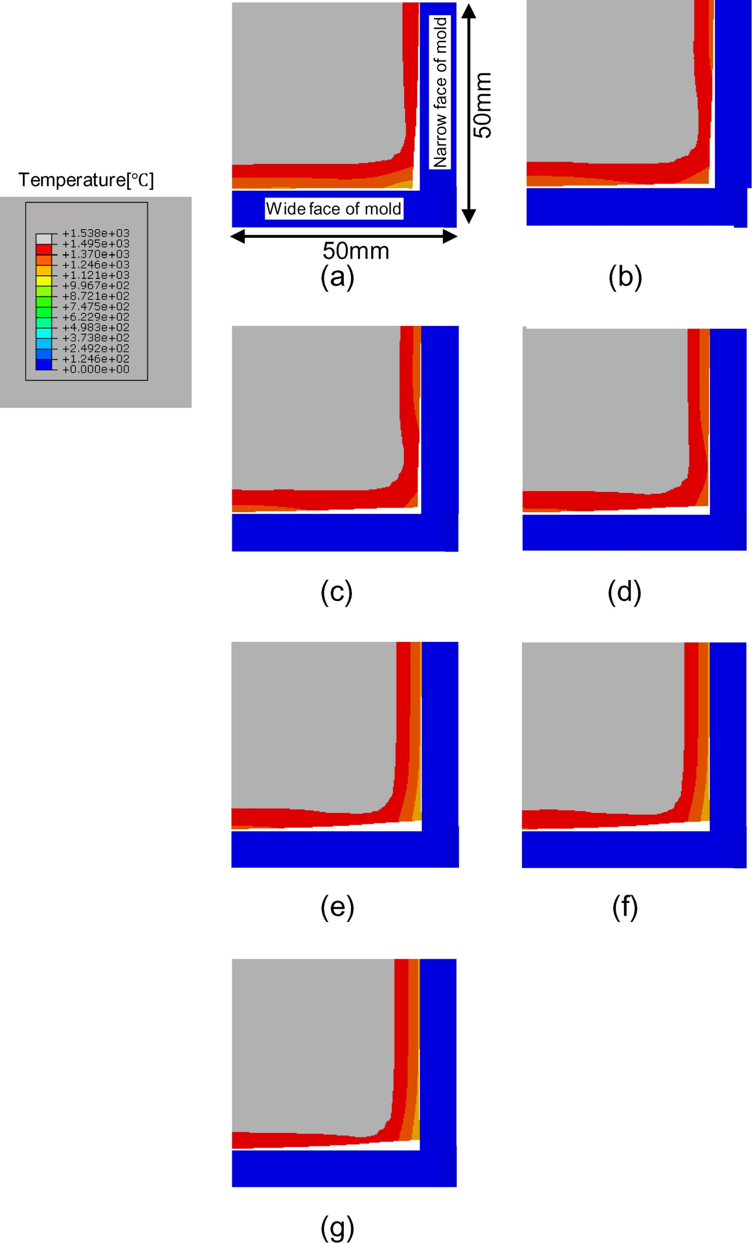
The influence of the heat flux difference ratio R between the wide side mould and the narrow side mould given by Equation (11) on the unevenness of the solidified shell near the corner was evaluated. Figure 11 shows the solidified shell temperature distribution and the shell deformation at 300 mm below the meniscus under the conditions of mould flux A, MTW
= 0%/m, MTN
= 1.1%/m, Vc
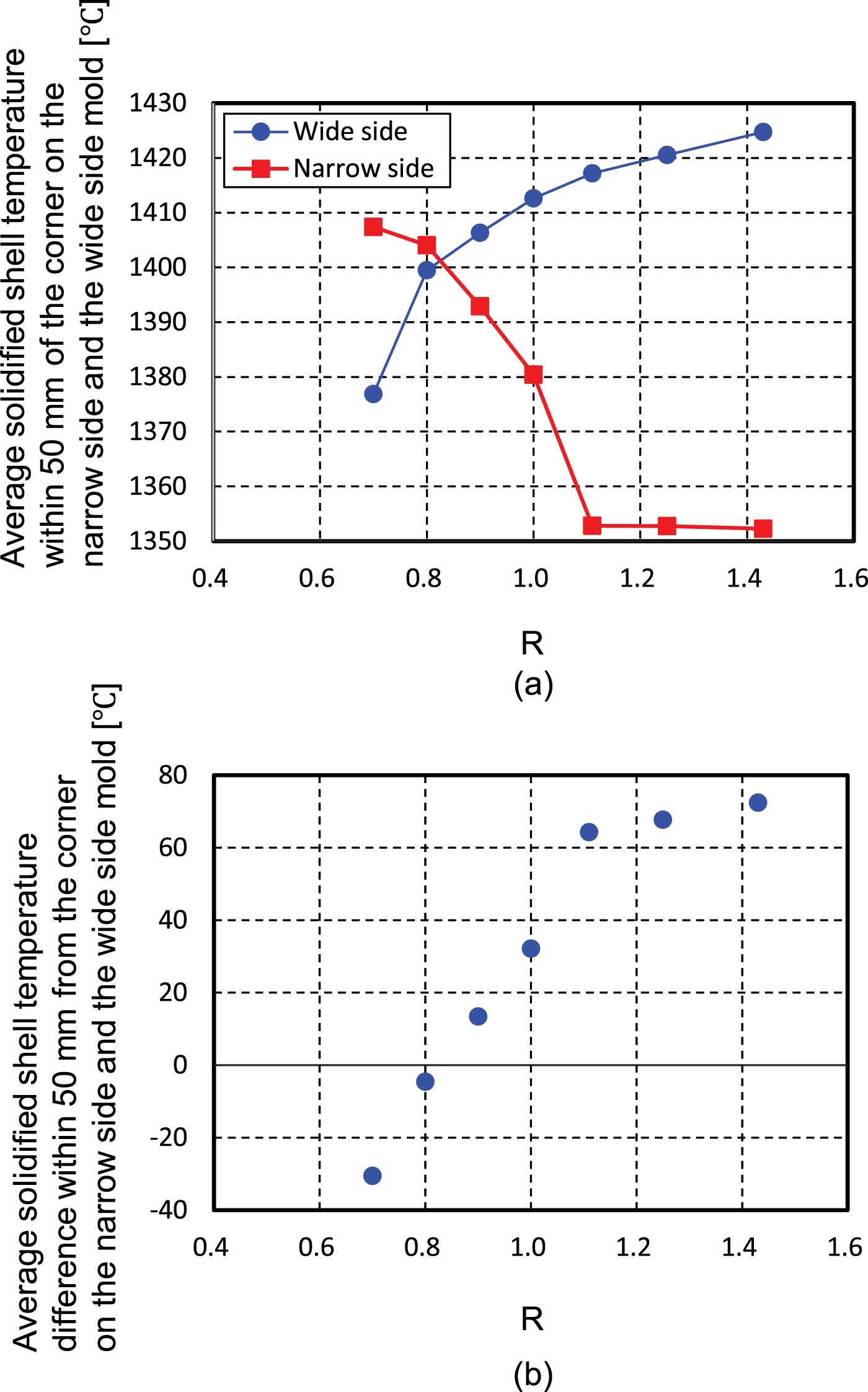
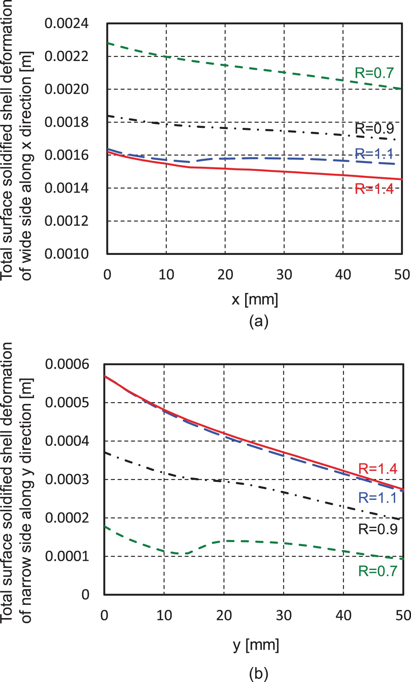
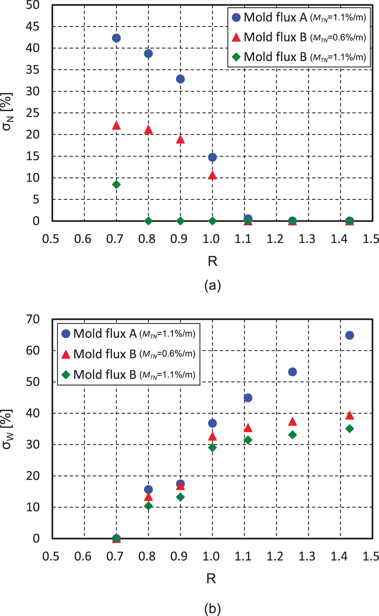
= 1.5 m min–1 and R = 0.70, 0.80, 0.90, 1.00, 1.11, 1.25, or 1.43. It is confirmed that this calculation results show a solidification retardation area near the corner due to the unevenness of solidified shell and this simulation results of solidified shell structure are similar to the actual macro structure where bleeding occurred during continuous casting shown in Figure 1. Figure 12 shows the average solidified shell temperature and the average solidified shell temperature difference within 50 mm from the corner on the narrow side and the wide side moulds. These results confirmed that the solidified shell temperature at the wide side increases with increasing R because of the smaller heat flux. Further, Figure 13 shows the total surface solidified shell deformation with shrinkage of the wide side mould along the x-direction and narrow side mould along the y-direction at different values of R. The amount of deformation in the x-direction increases with smaller values of R, whereas that in the y-direction increases with increasing R. From the results shown in Figures 11 and 12, it is found that the heat flux difference between the wide side and narrow side moulds affects the solidified shell deformation due to the shrinkage of the solidified shell. As the mechanism of this phenomenon, it is considered that the solidified shell is deformed in the direction of the larger heat flux side from the smaller heat flux side, and as a result, a gap is formed on the smaller heat flux side. Figure 14 shows the relationship between R and Deformed geometries of solidified shell and air gap of (a) R = 0.70, (b) R = 0.80, (c) R = 0.90, (d) R = 1.00, (e) R = 1.11, (f) R = 1.25, and (g) R = 1.43 at 300 mm from the meniscus (mould flux A, MTW
= 0%/m, MTN
= 1.1%/m, Vc
= 1.5 m min–1). (a) Average solidified shell temperature within 50 mm of the corner on the narrow side mould and the wide side mould and (b) average solidified shell temperature difference within 50 mm from the corner on the narrow side and the wide side mould (mould flux A, MTW
= 0%/m, MTN
= 1.1%/m, Vc
= 1.5 m min–1). Total surface solidified shell deformation of (a) wide side mould along x direction and (b) narrow side mould along y direction (mould flux A, MTW
= 0%/m, MTN
= 1.1%/m, Vc
= 1.5 m min–1). Relationship between R and (a) σN
and (b) σW
with mould flux A and mould flux B at 300 mm from the meniscus (MTW
= 0%/m, Vc
= 1.5 m min–1). Relationship between distance from the meniscus and temperature with mould flux A and mould flux B (MTW
= 0%/m, MTN
= 1.1%/m, Vc
= 1.5 m min–1, R = 1.0).


Influence of casting speed
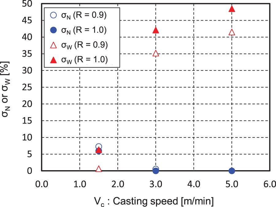
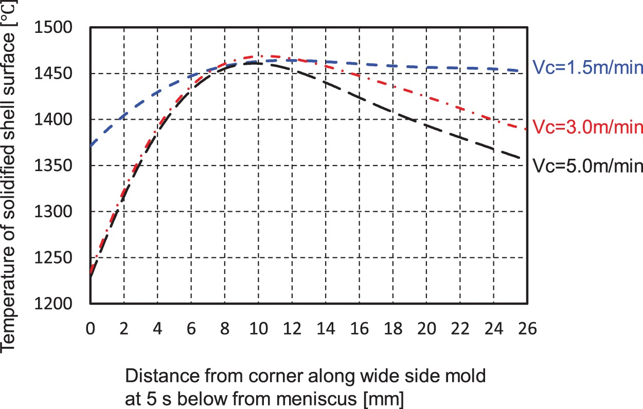
Next, the influence of the casting speed on uneven solidification within 50 mm of the corner was evaluated. Figure 16 shows the relationship between the casting speed vc
and Influence of casting speed on σN
and σW
at 5 s from the meniscus (mould flux A, MTW
= 0%/m, MTN
= 1.1%/m). Relationship between distance from the corner along the wide side mould and the temperature of the solidified shell surface.


Plant test results
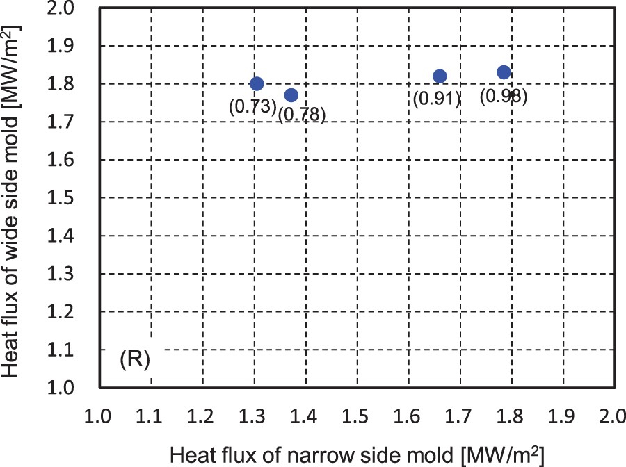
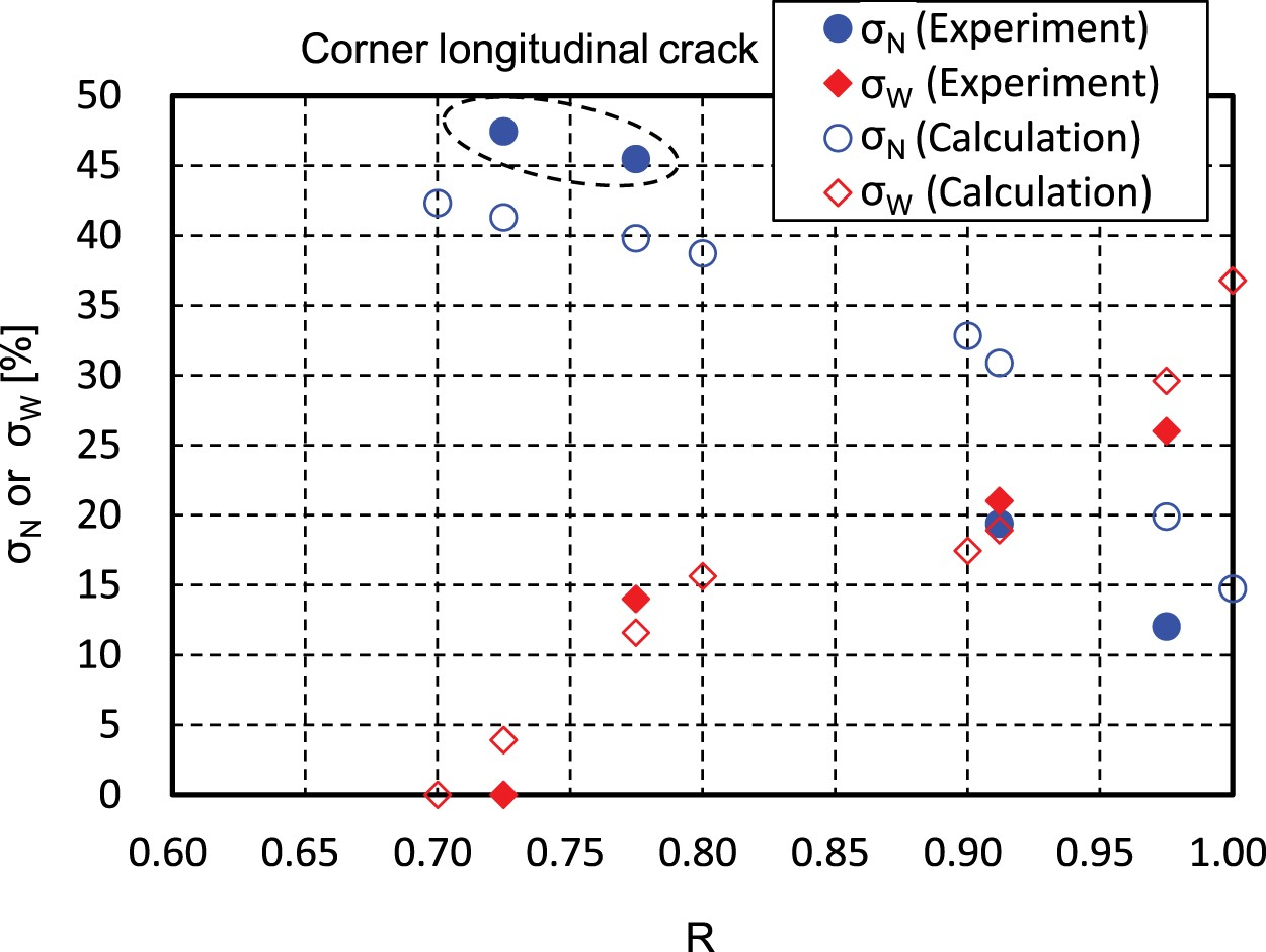
Figure 18 shows the heat flux of both the wide and narrow side moulds at 50 mm below the meniscus and each R conditions are given as indicated by the numbers in parentheses. Figure 19 shows the relationship between R and Relationship between heat flux of the wide and narrow side moulds at 50 mm below the meniscus. Relationship between R and σN
or σW
in the both plant test and calculation results. Comparison of casting conditions between plant test and simulation in Figure 19.


Conclusion
The effects of the heat flux difference between the wide side and narrow side of the mould, the taper value of the mould, the casting speed, and the cooling rate of the solidified shell in the mould on the air gap formation, the solidified shell deformation behaviour and the unevenness in the solidified shell near the corner in the mould were evaluated through a FEM analysis and plant tests using a commercial slab continuous caster. The results are summarized as follows. Optimization of the taper values of both the wide side mould and the narrow side mould is important for reducing uneven solidification near the corner, as the taper values affect the solidified shell deformation on both the wide side and the narrow side. At high casting speeds, the thickness of the mould flux infiltration in the gap becomes small, and it is considered that this condition causes increased solidification unevenness. The heat flux difference between the wide side and narrow side moulds affects the solidified shell deformation due to the shrinkage of the solidified shell. The solidified shell is deformed in the direction of the larger heat flux side from the smaller heat flux side, and as a result, uneven solidification increases on the smaller heat flux mould side. This study also clarified the fact that mild cooling by using an appropriate mould flux is effective for decreasing this uneven solidification. The heat flux difference between the wide side mould and the narrow side mould and the uneven solidification in the vicinity of the corner were evaluated by plant tests with a commercial slab continuous caster. It was found that longitudinal cracks were easily generated in the vicinity of the corner when the heat flux difference and uneven solidification between the wide side mould and the narrow side mould were large, and the agreement of the experimental results of the unevenness of the solidified shell with the results of the model calculations was confirmed. Based on the above results and considerations from simulation and plant test, the optimization of the heat flux difference between the wide side and narrow side moulds is required in order to suppress the uneven solidification near the corner in the mould.
Footnotes
Disclosure statement
No potential conflict of interest was reported by the author(s).