
Abstract
A novel setup of fluidized bed was developed to study the reduction of iron oxides by pure hydrogen. The setup enabled the introduction of powder directly to pure hydrogen atmosphere at experimental temperature. The arrangement was to minimize the experimental uncertainties due to gas switching. Hematite and magnetite powders were studied in the temperature range of 768-888 K. Reduction rates of the two powders were found to be similar. For both powders, the reduction rates were very high before the O/Fe ratio reached 0.5. Thereafter, the reduction was sluggish. SEM analyses revealed that the later stages of reaction was controlled by diffusion through the product layer on bigger particles, irrespective of the type of oxide powder. The results have indicated that both hematite and magnetite powder could be employed in fluidized bed. The results have also suggested that process optimization is essential regarding the sluggish reaction below 0.5 O/Fe ratio.
Introduction
Fluidized bed reactors for hydrogen reduction of iron ore used today still demand improvements and further development. Reduction of fine powder of iron ore can be an economically sound process since it can take both the ore powder, and the fines generated in and after the pelletizing process. Because a coarser powder can be utilized when fluidizing, compared to the pellet reduction route, it might offer an additional economic advantage. And as the fluidized bed also tends to have a faster reduction rate compared to pellets, the process temperature can be lowered, and the process time can be reduced.
Some iron ore deposits, this is especially true in Sweden, are mainly in the form of magnetite. Pellets based on magnetite are oxidized into hematite during pellet production. This is usually an advantage, since mechanical and metallurgical properties are improved in the process. When fines are used directly the same might not be true. Keeping the ore in the form of magnetite would decrease powder processing and should help with energy savings due to the lower oxygen content. Another important possibility by using fluidized bed is the facility of using industrial fines, such as pellet screenings.
In view of the potentials of the fluidized bed production route, a number of industrial scale plants have been operated, but the commercial success has been limited. The FIOR process was operated in Venezuela from 1977; while the Iron Carbide and Circored processes were in Trinidad. Today, the only operating plant is the FINMET plant built for Orinoco Iron, but the production is limited by availability of iron ore and natural gas. The only industrial scale DR plant using only hydrogen as reduction gas is the Circored process. Primetals will be commissioning a pilot scale plant during 2020. In Sweden, HYBRIT is a continuing project which aims at a solution for fossil-free steel production. A production rout based on hydrogen is expected to be fully developed by 2035. It is expected to be fully implemented in Sweden and Finland by 2045, thus reducing the Swedish CO2 emissions by 10% and Finnish by 7%. The current study is a part of the initial studies conducted for this project, where the possibility of utilizing fluidized bed is investigated.
Many studies have been carried out on a lab scale [1–8] to support the development of the fluidized bed for the industry. The studies have provided a lot of useful information about the reduction and fluidization properties of iron ore powder in fluidized beds, it is common practice in many studies [3–8] to switch inert gas to reaction gas in the reactor to start the reaction. Since the particles are very small, the effect of gas switching on the reduction might play a considerable role. This would be more profound when a bigger reaction chamber is used, in which a good control of the hydrogen partial pressure would be extremely difficult during the gas-switching period. The gas composition and experimental temperature have strong impact on the morphology of the reduced sample [9,10]. The formation of whiskers is shown to be related to the amount of CO in the reduction gas, and utilizing a pure hydrogen atmosphere inhibits the growth of whiskers [10]. Agglomeration and sticking is found in hydrogen reduction with temperatures exceeding 873 K [11].
To eliminate the effect of gas switching and gain a better understanding of the reaction mechanism in the fluidized bed, a new experimental design is used in the present work. The setup allows introduction of the oxide powder directly into the fluidized zone with 100% reduction gas and at a pre-determined temperature. By dropping the powder from a cold zone in the setup into the hot zone. The powder is assured to be fully fluidized from the moment it hits the filter forming the bed in the hot zone. Two types of industrial powders are studied, one consists mostly of magnetite and the other consists of both magnetite and hematite.
Experimental
The experimental setup is schematically shown in Figure 1. A vertical resistance heated furnace having high temperature limit of 1473 K was employed. It had a type-S thermocouple placed in the refractory wall just outside the outer tube for temperature control. The quartz outer tube had a 95 mm ID and was used as the main chamber, inside which the inner tube with the fluidized bed was kept. The inner quartz tube had a 45 mm ID, its middle part was made narrow (see Figure 1(A) so that a sintered quartz filter (with 30 mm in OD, and porosity 1) could be kept in position. The quartz filer was fixed on the wall of the inner quartz tube by melting the two parts together. As shown in Figure 1(A) a type-K thermocouple is positioned in the inner tube 5 mm above the filter. Special care was taken to make sure the thermocouple was not touching the wall. A new design was implemented in order to introduce the powder into the fluidized bed zone when a stable gas temperature, composition and flow rate had been established. The powder delivery system was placed inside the inner tube, suspended in the cold zone of the furnace, Figure 1(B). The position of the powder delivery system is adjustable along the length of the tube, from the cold-zone down to the filter. If pre-heating of the powder was needed the powder position could be changed. The powder delivery system consisted of a stainless-steel tube with a detachable bottom and open top. Keeping the top end open was to keep the powder in the same atmosphere as in the reaction zone. To release the powder, the bottom of the powder container was moved down relative to the container by a steel pushing rod. This would allow the powder to be dropped onto the filter forming the fluidized bed immediately. The fluidized bed setup, with A and B showing the filter part (A) and the powder introducing system (B) in greater detail.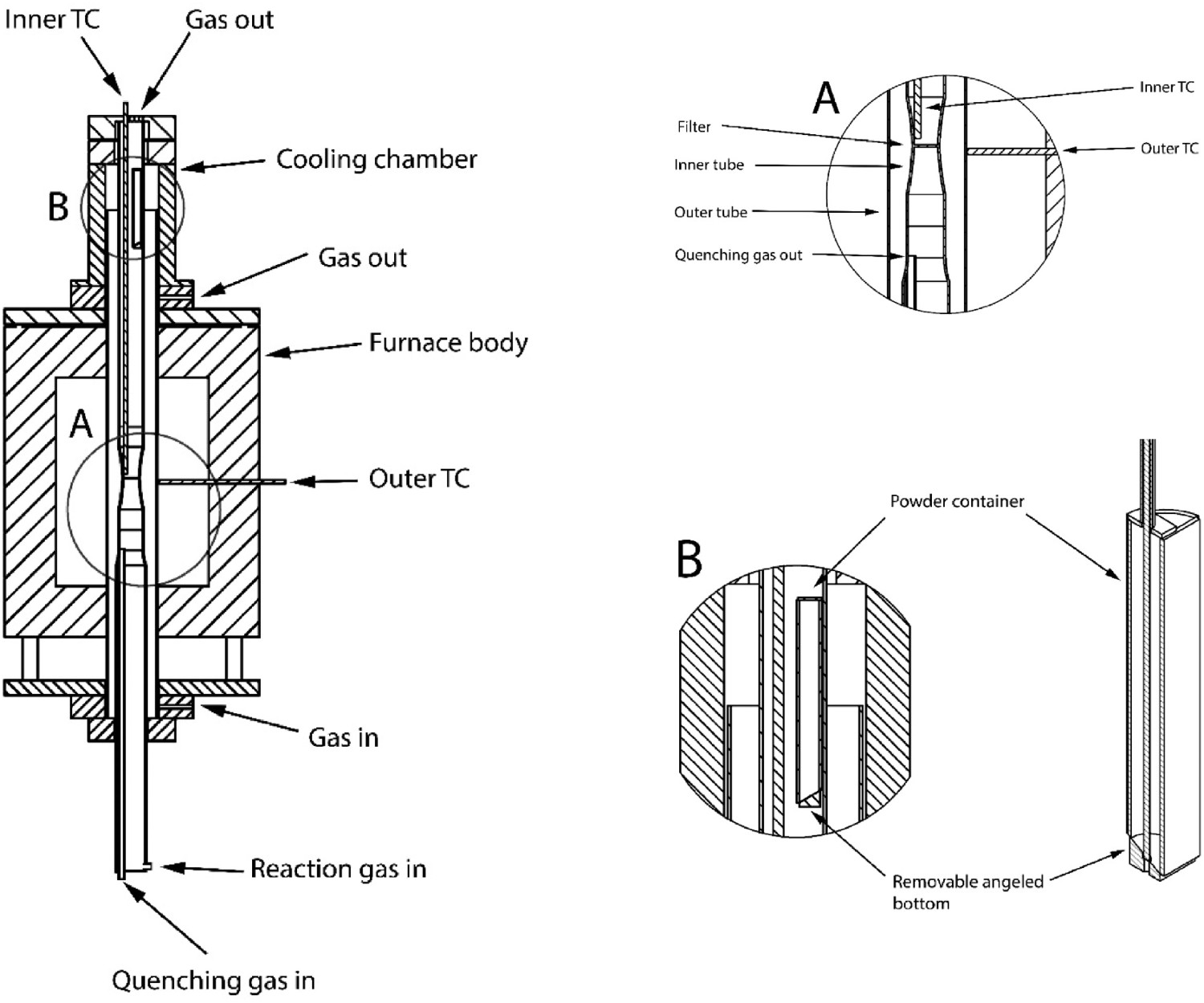
The whole system was sealed using Viton O-rings, so that no hydrogen (or any reaction gas) could escape from any connection point. An inlet for argon gas was placed at the bottom of a water-cooled aluminium cap at the lower end of the chamber. The position of this inlet was between the two quartz tubes. This arrangement ensured a constant inert gas flow between the tube of fluidized bed and the air outside the outer quartz tube, for safety consideration. The reaction gas was introduced from the bottom of the inner quartz tube, under the fluidized bed. This part of the reaction chamber (below the filter) was filled with small quartz rings, which ensured a good mixing and pre-heating of the reaction gases. The argon gas used for stopping the reaction in the bed had a bypass through these rings to minimize pre-heating. The outlets of the gases were placed on the upper ends of the inner tube. The flow rates of the inert gas and reaction gases were controlled by Bronkhorst High-Tech mass-flow meters.
The main difference between this setup and previous ones is the powder release mechanism. Standard tests today are conducted by fluidizing the powder in an inert gas and heating up the bed under an inert flow. The reaction is started by switching the gas from inert to reactive. This creates an initial timestep where the atmosphere composition is unknown, changing, and difficult to track. Note that since the surface area is enormous in this initial period, the uncertain partial pressure of the reaction gas would have huge impact on the reaction and therefor the results obtained. With the current setup the furnace is heated up without the powder, and the partial pressure of the reaction gas is ensured before the powder is introduced. The powder is kept cold as to not start the reaction prematurely. The reaction is started by dropping the powder into the furnace hot zone. Note that with this new setup, a certain temperature drop is expected when the powder is introduced, since the powder is cold initially. However, the temperature is easily tracked through the thermocouple. The temperature is more easily recorded compared to the PH2 during the gas switch.
Gas flow rate
There have been studies on the flow rate needed to generate a fluidized bed. The minimum flow rate for a fluidized bed can be calculated and the equation can be found in the literature [12]. Since the present study aims at a fully fluidized powder bed with a wide particle size distribution, this equation could not be employed. To make sure of full fluidization, the flow rate was chosen experimentally based on room temperature experiments. An argon flow of 31 nl min−1 was found to fully fluidize the entire depth of the powder bed in the current setup.
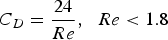
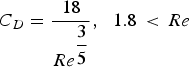
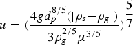
At the experimental temperature, the gas density is lowered. To determine the flow rates at high temperature, the expression of terminal velocity of the particle was employed, Equation (1):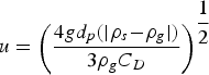


Calculated flow rates for the fully developed fluidized bed at different temperatures.
Materials
Composition and size distribution of powders used in this study
Procedure
Before each experiment, the powder delivery system was filled with 14 g of powder and suspended in the top of the inner tube. The furnace was carefully sealed. Thereafter, both the space between the outer and inner tube, and the inner tube were flushed first with argon at 1 nl min−1 for 30 min, after which the flow rate was lowered to 0.3 nl min−1. A constant flow of argon at this flow rate was kept through the space between the two tubes throughout the whole experiment. The reaction chamber was heated up to a temperature 115 K above the experimental temperature. 120 min was allowed for the furnace to stabilize at the wanted temperature. Subsequently, reaction gas (H2) was flushed into the inner tube at fluidization flow rates. Note that the high flow gave a marked drop in temperature, the furnace temperature stabilized at a new temperature after 30 min of flushing, generally 90 K below furnace temperature. At this point, a final fine tuning of the temperature was done to hit the experimental temperature with the fluidization flow rates.
After the temperature was stabilized, the powder was dropped onto the filter. The powder was fluidized for a fixed amount of time in the reaction gas, after which the reaction was stopped by replacing the reactive fluidizing gas with argon. The powder was fluidized in argon for 7 min. Thereafter, the flow of argon was lowered to 0.3 nl min−1, this flow was kept until the furnace was cold. The furnace was ramped down at 10 K min−1 when the reaction gas was switched off. While most of the experiments were conducted with a reduction time of 15 min, some experiments were terminated at shorter reduction times to study the reduction mechanism.
Preliminary experiments showed that the reduced powder self-ignited easily when exposed to air. Hence, a special unit was designed to be connected to the reaction chamber, so that the powder could be delivered into a bottle under constant argon atmosphere. This was found to be essential to avoid self-ignition and keep the reduced powder from any degree of re-oxidation.
While most of the experiments were conducted by introducing the powder into hydrogen atmosphere at the experimental temperature, two experiments were carried out using the traditional method wherein the powder was heated up in argon before the argon flow was switched to hydrogen.
In view of the loss of particles small than 76 µm, the degree of reduction of each experiment was determined by the total content of oxygen. This was done using LecoONH with a ± 10% error margin of the measured value.
SEM analysis was conducted on the samples using a Hitachi S-3700N. Powders were mixed with Struers EpoFix epoxy and cast in 25 mm diameter dies. The dies were subjected to vacuum to remove any entrained gas bubbles. After hardening the powder/epoxy cylinder was polished, finishing with 0.05 µm alumina suspension and sputtered using a Jeol JFC 1300 with an Au/Pt target.
Results
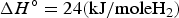
The temperature in the powder bed was measured throughout the experiments. A temperature drop of about 10–20 degrees is noticed. This decrease could be explained by three reasons. First, the powder had lower temperature than the bed chamber before addition. Second, hydrogen has different physical properties compared to argon. Thirdly, the total vast surface area results in fast reduction according to reaction (6), which consumes a lot of heat [20]: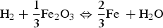
Reduction
To present the results, the O/Fe ratio defined in Equation (7) is employed.


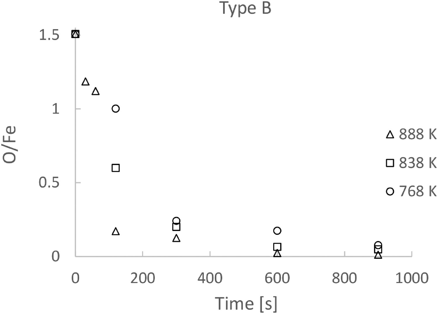
The ratio as a function of time for Type A and Type B powders are presented in Figures 2 and 3 respectively. Note that each experimental point shown in the figures was obtained in an individual reduction run. The figures clearly show the reaction rates increases with temperature, especially in the initial stages of the reduction for both powders. On the other hand, the effect of temperature on the reaction rate becomes less profound after about 300 s. It is also seen in the figures that the reduction rates become very low after 300 s, irrespective of the type of powder and experimental temperature. The reduction is almost stopped after 600 s. After 900 s, the reductions at all temperatures have come to a similar O/Fe ratio. O/Fe ratio for Type A powder as a function of time, for three temperatures. O/Fe ratio for Type B powder as a function of time, for three temperatures.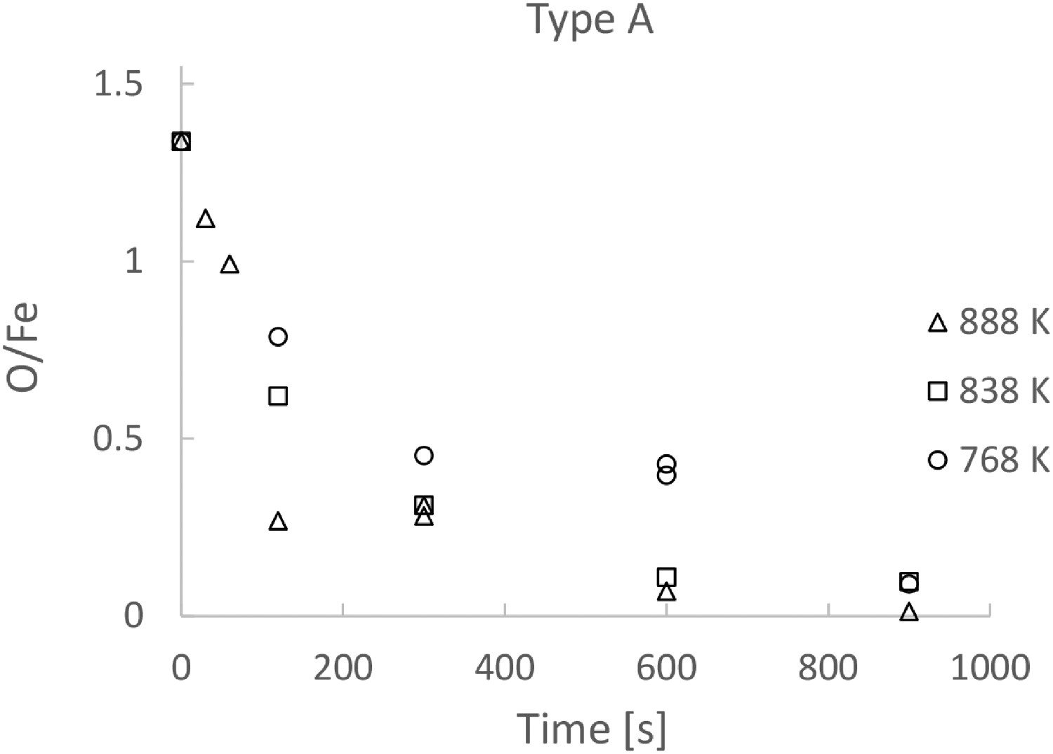
SEM analyses were carried out on some of the samples after reduction. The SEM micrographs of the samples of Type A after 30, 60, 120 and 600 s of reduction are presented in Figure 4(a–d), respectively. As seen in Figure 4, almost all the particles consist of a dense Fe layer surrounding a core of oxide. Four timesteps of Type A powder at 888 K, showing the reduced layer thickness growth over time.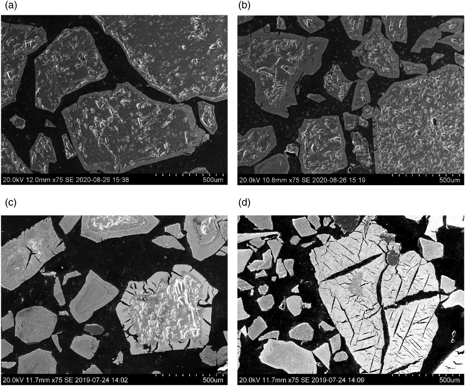
Figure 5(a–d) presents the SEM micrographs of the Type B sample after 30, 60, 120 and 600 s reduction, respectively. The similarity between Type A and Type B is evidently brought out by Figures 4 and 5. Four timesteps of Type B powder at 888 K, showing the reduced layer thickness growth over time.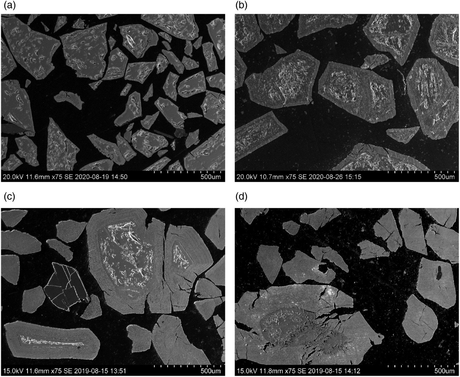
Figures 4(d) and 5(d) evidently show that the bigger particle in the sample after 600 s of reduction still consist of both Fe and oxide layers, while the small particles are completely reduced. Irrespective of the reaction time and reduction temperature, the produced Fe phase is considerably dense. Note that some cracks in the metal phase are observed in some of the particles. The larger particles seem to crack to a larger extent, as can be seen in Figures 4 and 5.
To examine the growth of the product layers and compare the behaviours of the two types of powders, Figure 6 shows the SEM microphotographs of the product layers at different reduction times with higher magnification. While Figure 6(a,b) presents the samples for Type A at 30 and 60 s of reduction, Figure 6(c,d) shows the particles of Type B at the same two reduction times. The figures clearly show the growth of the product layer over time, and the layers of oxides inside the pure iron product layer. In the case of Type A powder, as seen in the Figure 6(a), an iron layer is formed after 30 s. For type B powder even magnetite is formed, Figure 6(c). At 60 s, three layers are found in the Type A particles; namely iron-wüstite-magnetite from the surface towards the centre, Figure 6(b). For Type B powder the layers are iron-wüstite-magnetite-hematite, Figure 6(d). SEM micrographs at a higher magnification, to clearly show the structural evolution of the reduced layers growth. All powders are run at 888 K.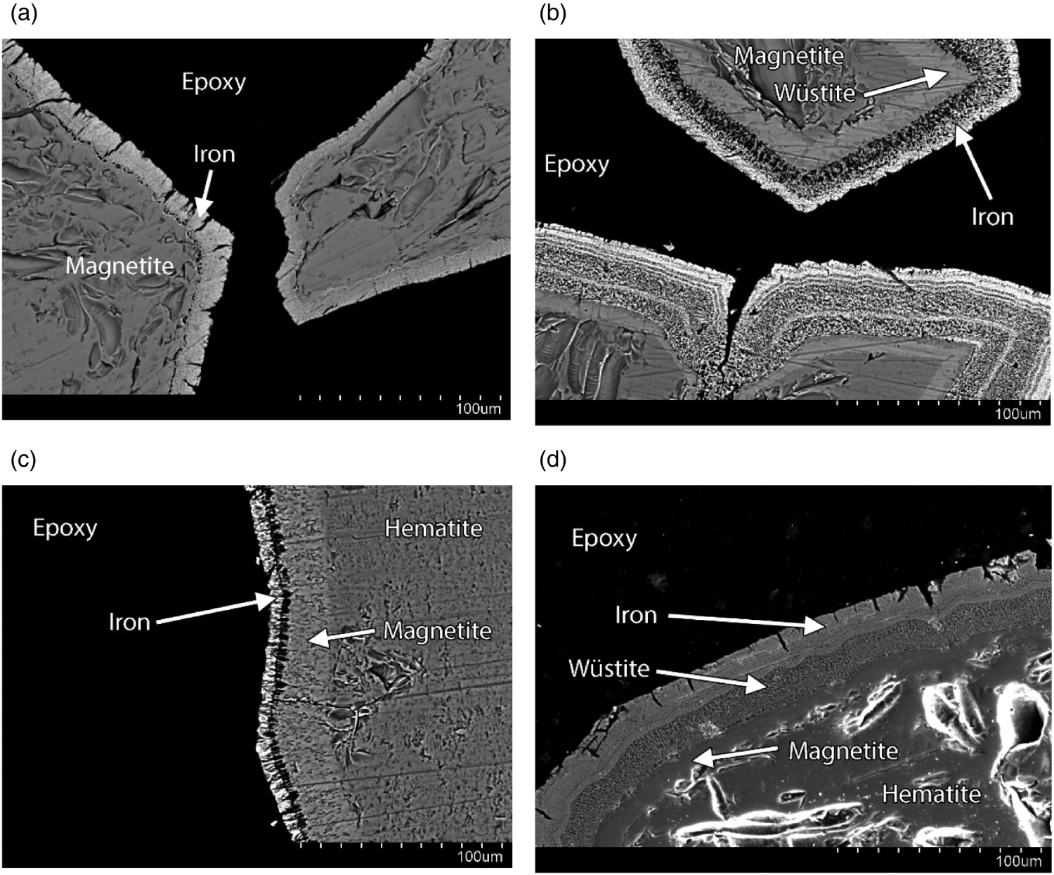
Discussion
Repetitions of some experiments were conducted to examine the reproducibility of the experiments. As seen in Figure 2, the dual measuring points for 768 K at 300 s and 888 K at 600 s show evidently the agreement between different runs under the same experimental conditions.
O/Fe ratio for Type B powder after 120 s, comparing two experimental setups; the one used for this work and the conventional method
Note also that the temperature drop due to the endothermal heat of the reduction is inevitable even in the traditional experimental setup, though very little discussion regarding the temperature drop can be found in the literature. Most of the works have assumed that the temperature in the powder bed is constant and no monitoring of the temperature was excessed and discussed. It seems to be common practice to dilute the powder with silica or alumina powder, and use low concentrations of hydrogen [1,3,6,21,22]. While the dilution might lower the effect of the heat consumption, since there is heat stored in the un-reacting powder, it would introduce other uncertainties, for example, the contact of the gas to the particles.
It should be mentioned that Liu [22] also added powder into the reaction gas at a given temperature. However, the author also used a lot of alumina powder to dilute the iron oxide content and used low concentrations of hydrogen [22] due to the experimental setup. Therefor it is difficult to compare the two experimental setups.
No sticking is observed in the reduced powders. This can be attributed to the low reduction temperatures employed, as discussed by [2] and [11]. Lu and co-workers reported that using pure H2 as the reduction gas would avoid the formation of whiskers [10]. Hence, the use of pure hydrogen is another important reason for the absence of sticking.
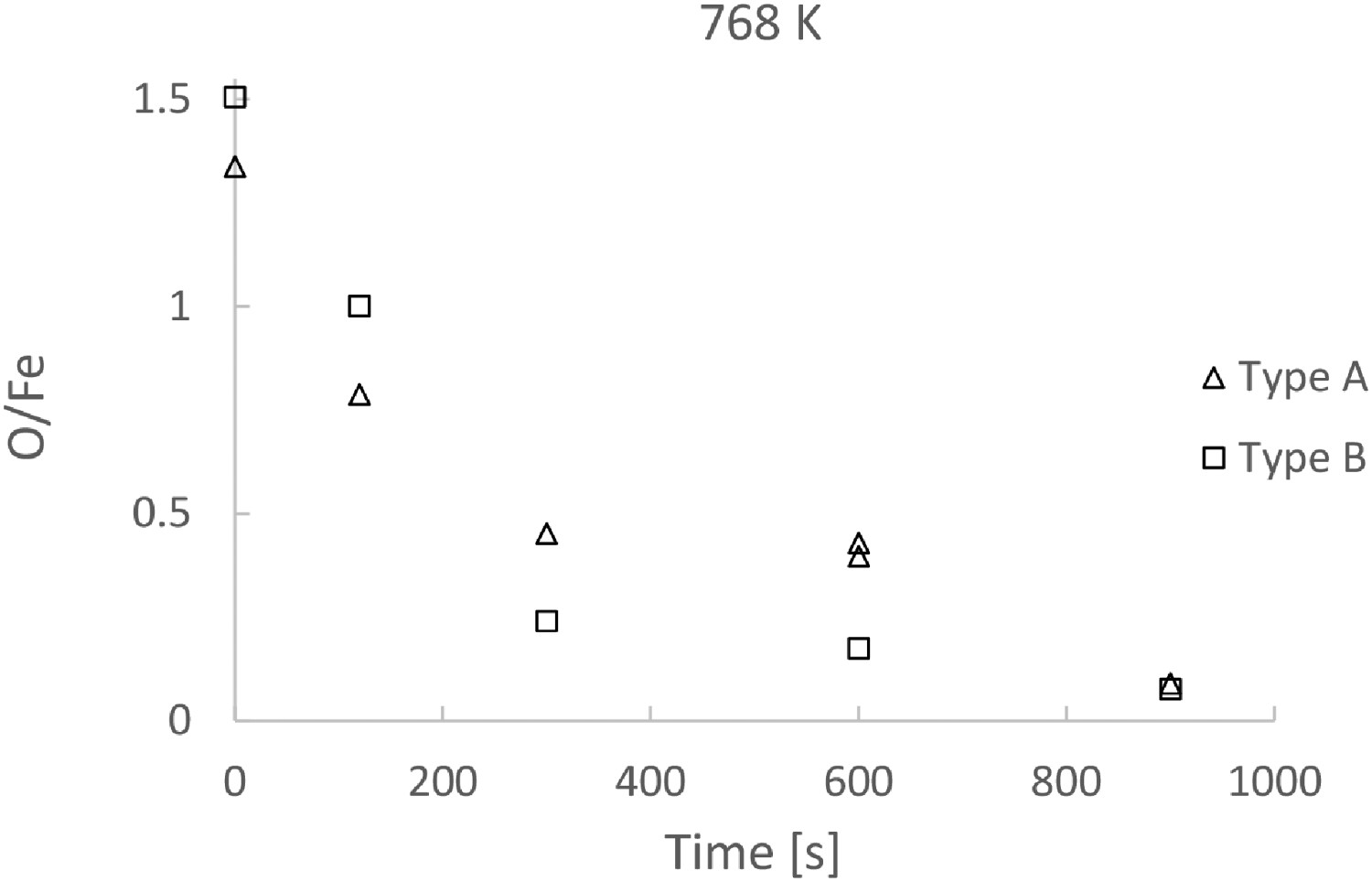
To compare the reduction rates of Type A and Type B, the O/Fe ratio of the two types of powder are presented as functions of reaction time in Figures 7 and 8 for reaction temperature 888 and 768 K, respectively. No substantial difference can be seen, though the O/Fe ratio is slight lower in the case of Type B. Note that in view of the loss of smaller particles, the only way to follow the ratio is to follow the loss of oxygen. Since the oxygen analysis associates with certain uncertainties, the difference in the reaction rates shown in the two figures is within the uncertainty level. Comparing O/Fe ratio of Type A and Type B as a function of time, at 888 K. Comparing O/Fe ratio of Type A and Type B as a function of time, at 768 K.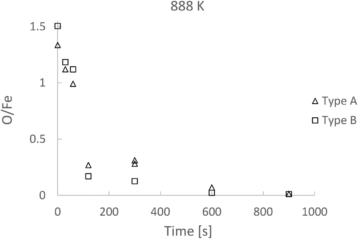
Figures 2 and 3 show that, reaching an O/Fe ratio lower than 0.02 requires 15 min of reduction time at 888 K for both powders. It is interesting to mention that the drawbacks of magnetite pellets in the processes of reduction are mostly related to the mechanical properties of the pellets. Since the fluidized bed does not use pellets but powder, it is possible to use the ore of magnetite directly without oxidizing it to hematite. This would lead to a big energy saving and considerable reduction of H2 consumption.
Figures 2 and 3 (also Figures 7 and 8) evidently show that the reaction rate become very low after 300 s at 768 K and after 120 s at 888 K, irrespective of the type of powder. As revealed by Figures 4–6, a considerable dense layer of Fe is formed on the particles. Figure 6(a–d) shows the progress of the growth of the product layer, and the stepwise reduction inside the grain. For Type A, a layer of Fe is formed on the surface. Between the Fe layer and the unreacted magnetite core, a wüstite layer is formed. This can be easily explained by the increasing oxygen potential towards the centre of the particle due to slow hydrogen diffusion. In the case of Type B, 3 layers are found outside the unreacted hematite phase, namely magnetite, wüstite and Fe. Again, due to the increase of oxygen potential toward the centre, magnetite is found next to hematite, and wüstite is found between magnetite and Fe. Nevertheless, for both types of powders, the growth of the product layer is evident. Owing to the formation of the layers, further reduction would require the diffusion of hydrogen gas to the reaction front, and there is a specific reaction front for each reduction step. When the layers become too thick, the diffusion process becomes very slow. This would explain the very low reduction rate after 300 s.
Since a very high flow rate of hydrogen gas is employed, the mass transfer in the gas phase is very fast. The rate controlling step of the reduction would be the H2–H2O interdiffusion through the product layer after the initial stage of reduction. As shown by Figures 2 and 3, the reaction rate is already dominated by diffusion after 120 s. It should be mentioned that some cracks are formed in the product layer (see Figures 4 and 5). The micro cracks would be of some help for the transfer of gas. However, the path formed by the cracks for gas transfer is still limited considering the mass of the particle and total reaction interface. The micrographs presented by Matthew and Hayes [9] show similar microstructures to the ones observed here. Reduced layers found by them are thinner even though they run similar times and temperatures. This could be explained by the mixed hydrogen/water vapor atmosphere used by the authors [9]. A water enriched atmosphere would reduce the concentration gradient between the reaction interface and the gas phase, slowing interdiffusion and the reaction rate.
Note that the product layer of Type A (Figure 6(a)) is slightly thicker than Type B (Figure 6(c)) after 30 s. This is in accordance with the reduction curve in Figure 7, where the O/Fe ratio is slightly lower in the case of Type A after 30 s. On the other hand, the difference in the reduction rate is small.
Figure 7 shows that the reduction at 888 K needs less than 120 s to reach a reduction extent of 0.8, while Figure 8 shows that reduction at 768 K needs 360 s to reach the same extent. The comparison suggests a higher process temperature in industrial practice. Although the time required is much shorter, to keep the reaction temperature above 890 K would need more energy compared to 770 K. But the shorter reduction time would save energy in turn. An optimization of the process with the reaction time is necessary to address this aspect. All the reduction curves indicate that it would take considerable time to go from 80% reduction to 97% reduction at both temperatures.
Summary
A novel experimental setup has been developed to study the hydrogen reduction of oxide powder in a fully fluidized bed. In this set up, the effect of gas switching on reduction has been avoided by introducing the powder directly into the reaction atmosphere at experimental temperature. The results have shown that the reduction carried out in the newly designed equipment is faster than in the traditional setup. Experiments have been carried out using this setup to study hydrogen reduction of two types of industrial fines. The SEM micrographs of the reduced and partially reduced samples show the reaction in the later stage is controlled by diffusion of gas through the dense product layer. The reduction has been found to reach a O/Fe ratio of 0.5 in a short time, e.g. only 120 s at 888 K. However, further reduction has been found to be slow due to the slow diffusion process. The experimental results have also shown that the reductions of magnetite powder and hematite powder have similar rates.
Footnotes
Acknowledgements
This work has been conducted as part of the HYBRIT research project RP1. We gratefully acknowledge financial support from the Swedish Energy Agency. HYBRIT (Hydrogen Breakthrough Ironmaking Technology) is a joint initiative of the three companies SSAB, LKAB and Vattenfall with the aim of developing the world’s first fossil-free ore-based steelmaking route.
Disclosure statement
No potential conflict of interest was reported by the author(s).