
Abstract
The wear of industrial refractory materials was studied in contact with slag containing high amounts of FeO using the rotating finger technique. The thermodynamic equilibrium of the refractory slag systems was also determined in Thermo-calc® and FactSage™. The studied refractories were alumina spinel, zirconia, graphite, silicon carbide (SiC), magnesia-carbon (MgO-C), chromite (Cr2O3), and MgO-Spinel (MgO–Al2O3). The fingers were rotated in a FeOx (90wt%) – SiO2 (5wt%) – CaO (5wt%) slag for 3 hours in a molybdenum crucible at 100 RPM at 1700K. The wear of the refractory fingers was determined by dimensional changes and changes in composition of the slags. Only MgO-spinel refractories exhibited resistance to the slag. The thermodynamic equilibrium calculations were able to predict the experimental behavior when appropriate databases were used, with the exception of the chromite slag.
Introduction
In ironmaking, the blast furnace is the industry standard and has been so for centuries. Owing to the increasing awareness of the potential hazards of greenhouse gas emissions (GHG) for the climate, alternative process routes are explored to reduce the CO2 emissions associated with ironmaking [1]. A proposed alternative ironmaking process is the IronArc process, where iron ore is melted using superheated gas from electrical plasma generators (PGs). With additions of hydrocarbons from liquid petroleum gas (LPG) or liquid natural gas (LNG) into the molten slag, the iron oxide is reduced to molten iron. This process route will reduce the CO2 emissions from the reduction of iron ore by at least 50% when compared with the Blast Furnace [2]. Since all energy in the IronArc process is supplied by electricity rather than burning of coal or coke, the only CO2 emissions produced are from the reactions between the injected hydrocarbons and oxygen in the iron oxide slag.
The production of crude iron in the IronArc process will occur in two discrete steps to maximize the carbon efficiency. In the first step, the iron ore will be heated and melted by superheated gas from a PG with additions of recycled CO from the second reactor. This will reduce the iron oxide slag from hematite (Fe2O3) to wüstite (FeO x ). After the initial reduction, the slag composition is expected to be 90% FeO x – 5% SiO2 – 5% CaO. The slag is then transferred to a second reactor via a slag runner, which prevents the transfer of process gas. In the second reactor, superheated hydrocarbons are injected into the melt with another PG. This reduces the slag to molten crude iron. To facilitate the IronArc process, a refractory material which can withstand contact with the molten iron oxide slag for an extended amount of time is required [2].
Refractory materials are essential in the steel and metals industry for use in ladles and furnaces to contain high-temperature melts and slags. Conventional refractory materials used in the iron and steel industry include MgO, MnO, Al2O3, ZrO2 and Cr2O3-based bricks. These compounds combine to form mineral structures which have high thermal stabilities [3].
Despite high thermal stabilities, refractory materials are subject to reactions from contact with slag or molten metal. Owing to the high temperature of the process, any reactions are expedited and may cause significant wear of the refractory due to chemical reactions [3]. In addition, the high-temperature environment may reduce the structural integrity of refractory materials and make them subject to an increased wear from erosion and mechanical damages. Therefore, the choice of a refractory material must be tailored to the process in question to maximize the campaign life of the equipment. The two major factors to consider when determining the appropriate refractory material are: mechanical wear from erosion due to flow and shear stresses in the process, and a chemical compatibility between the refractory and molten metal, slag, and process gasses. The internal thermo-mechanical stresses from heating and cooling cycles should also be considered.
It is known that increased amounts of FeO x in metallurgical slags are detrimental to refractory lifetimes and that metallurgical slags with high amounts of FeO x dissolve many refractory materials quickly. The mechanism for dissolution depends on the refractory material, but often includes chemical reactions and formation of phases with low melting temperatures [4]. Phases with low melting temperatures will quickly be removed from the refractory wall and cause a spalling of other insoluble particles. FeO x is an inevitable constituent of metallurgical slags for ironmaking and steelmaking but is generally not found in as high concentrations as in the IronArc process. The highest FeO x content in other metallurgical processes is ∼30% [5–7].
Very few studies have been done on refractory wear from slags with FeO x compositions exceeding 50%. Zhang and Seetharaman [8] performed a study on FeO x –SiO2–CaO–CaF2 slag with 45% FeO x for MgO refractory wear. Furthermore, a study by Oeters and Neuer shows that slags with FeO x compositions over 50% may be less aggressive to refractories of sintered magnesite [9]. Many other studies of FeO x -rich slags have instead focused on the viscosity or melting temperature of the slag, rather than the refractory wear [10,11].
The present study aims to evaluate the wear behaviour of a set of common refractory materials when being in contact with a metallurgical slag with a high FeO x content, under conditions found in the IronArc process. The interaction between such a slag and refractory has not been studied in previous work to the authors’ knowledge. The chemical reactions were estimated by thermodynamic equilibrium calculations in Thermo-calc® using the TCOX8 and TCFE9 database as well as FactSage™ using the FactPS, FToxide, and FTmisc databases [12,13]. Additionally, the dynamic wear was predicted by studying the shear stress using CFD simulations. The thermodynamic equilibrium calculations give a basic understanding of what refractory materials are viable for testing and help to explain the wear mechanisms.
The combined wear from chemical and dynamic factors was studied using high-temperature experiments using the rotating finger technique and using a controlled atmosphere. In the rotating finger experiments, a finger of refractory material is lowered into a molten slag and thereafter rotated to study the dissolution as a function of time. This method has been used extensively in the literature for studies of refractory wear [14–16]. Since the two mechanisms are studied using the same experiment, it is difficult to determine which of the wear mechanisms is the dominant one [17]. However, some studies have found that the forced convection in the rotating finger method is dependent on the ratio of the finger radius to crucible radius and thus the magnitude of the dynamic wear can be estimated [18].
The CFD study helps to determine the shear stresses on the rotating refractory finger to properly replicate the wear conditions in the up-scaled process. Work by Wang et al. [19] found that the dissolution rate of cylindrical rotating refractory fingers is mostly independent of the rotation speed, due to low radial velocity of the flow. However, shear stresses on the rectangular-shaped refractory finger used in the present study are expected to be dependent on the rotational speed.
The resistance of refractory materials to chemical and dynamic wear by corrosive slags is affected by both material properties and the production process of the refractory bricks. Factors such as porosity, grain size, and the degree of fusion between grains in a refractory brick can have as much of an impact on the corrosion resistance as the chemical composition of the refractory [3,5].
Composition of studied refractory materials in wt-%.
The chemical wear can be divided into two distinct mechanisms: oxidation–reduction reactions, and dissolution and diffusion. The magnitude of these effects is also dependent on the apparent density and pore size of the refractory, as well as the wetting properties between slag and refractory. An increased porosity corresponds to a larger surface area for the reaction between the slag and refractory as well as the potential for spalling of the refractory. Since the matrix and binder phase of the refractory materials often is the most porous and impure part of the refractory, it will be the weakest link that will be attacked first.
The mechanical wear can also be divided into two distinct mechanisms, namely erosion and penetration. Erosion is directly related to the flow rate of liquid over the refractory and can be evaluated in terms of the shear stress on the refractory wall [20]. Penetration is an enabler to the actual wear by corrosion or spalling. Spalling is the event where a piece of refractory is broken off the brick by shear stresses below the surface of the brick [5].
Iron oxide in metallurgical slags has been found to reduce the melting temperature of the slag significantly. Iron oxide will also react with many refractory materials and form low melting point phases, which increases the rate of the refractory wear [6,7]. Increased amounts of iron oxide have the potential to reduce the viscosity of the slag, which increases the wetting between the refractory and slag and increases the refractory wear by penetration [11].
MgO refractories react with FeO x –Silicate slags and form layers of magnesiowüstite under static conditions. This slows down the corrosion rate of the refractory, which is then controlled by the diffusion of Mg through magnesiowüstite [8]. Additions of carbon to magnesite refractories reduce the wetting of slag and thus reduce the refractory wear. Higher amounts of C in the refractory increase the C loss by oxidation from slag due to a formation of CO and CO2, which reduces the structural integrity of the refractory [21]. Since MgO has no liquid phase in contact with FeO x or Fe2O3, the wear by corrosion should in theory not increase with increased amounts of FeO x in the slag [22]. Additionally, MgO–C refractories in steelmaking applications experience the formation of a dense layer of MgO at the interface between refractory and steel [23]. Refractory bricks with dense layer formation have been shown to experience lower dissolution rates than bricks without the dense layer [24].
Magnesia–chromium refractories are common in the copper converting industry. For copper anode slags with 30–35% FeO x and 50% CuO, 8% SiO2, it was found that chromium-containing refractories were more resistant to corrosion than refractories without chromite [15]. Reactions between alumina–chromite refractories with slags containing SiO2 and CaO results in slag penetration and reactions with the matrix. Reactions with FeO x lead to the formation of a composite spinel of FeO x –Cr(Al)2O3. Furthermore, if MgO is present in the slag, a spinel of MgO–Fe2O3–Cr2O3 will form which decreases the rate of further degradation [25]. Reactions with CO-rich atmospheres also accelerate the brick corrosion by reactions with the refractory, but this may be avoided by increasing the chromite ratio in the refractory [26].
Zirconia is stabilized by magnesia, lime, or silica to increase the structural integrity of the bricks. A common stabilizer is alumina and silica to form an AZS refractory. The phase diagram of FeO x and ZrO2 shows that ZrO2 is stable at reactor temperatures up to an 80% dissolution of FeO x in ZrO2. This indicates that ZrO2-based refractories may be resistant to FeO x slags [27]. Other research results indicate that magnesia-stabilized zirconia is more resistant to corrosive slags than calcium-stabilized zirconia [14]. However, no magnesia or calcium-stabilized zirconia refractories were available for testing in the current study.
The corrosion resistance of high alumina spinel castable are more dependent on the spinel content rather than the porosity of the refractory. The formation of C2AS is detrimental to a refractory corrosion resistance due to its low melting temperature, which in turn increases the slag infiltration [28].
Alumina refractories are resistant to wear by most common steelmaking slags. Slags containing high amounts of FeO x lead to the formation of hercynite (FeAl2O4), which is stable and highly resistant to wear and thermal shock [29,30]. In combination with chromite, the alumina refractories show a high corrosion resistance towards most slags due to a low solubility in slags. Additionally, some additions of TiO2 may further increase the density and grain size of the refractory which increases the thermal shock resistance [31].
Alumina silica refractories are not suitable for use with FeO x -rich slags since the presence of FeO x causes a formation of liquid phases at low temperatures. When 25–35% FeO x has been absorbed into the refractory material, the formation of liquid phases is possible down to temperatures of 1478 K [32].
Method
Thermodynamic calculations
The chemical stability of refractory materials in contact with the IronArc slag was evaluated by using thermodynamic equilibrium calculations using Thermo-calc® with the TCOX8 and TCFE9 databases, and FactSage™ with FactPS, FTmisc and FToxid databases. The phase stability diagrams from such calculations provide information on the compatibility of slag–refractory systems and may help to predict the wear behaviour at equilibrium conditions. The phase stability diagrams do not give any information regarding the kinetics of the dissolution, but in combination with experimental studies, the phase stability diagrams may help to explain the dissolution mechanisms of the refractory materials [33,34]. The thermodynamic calculations also do not consider that the refractory is a compact piece of brick with a limited surface area. The calculations are more representative of the equilibrium of a homogenous mixture of the refractory material and slag than the actual experimental set-up.
This part of the study aims to investigate if it is possible to predict what refractories are thermodynamically stable at varying temperatures and slags by creating a system with the refractory constituents and the slag constituents. If the calculation shows that phases with high fractions of refractory materials are solid at a certain temperature, that is an indication that the refractory may be stable. If large amounts of the refractory constituents are found in liquid phases, that is an indication that the refractory is not stable at that temperature and the refractory has melted in the reaction with slag. If some of the refractory constituents are stable and some are not, the partial melting of the refractory may reduce the structural integrity of the brick and cause failure despite partial thermodynamic stability. This will allow for penetration of slag further into the refractory material which will lead to spalling of the grains and subsequent failure [5,35,36].
If new solid phases form above the melting temperature of the added slag, it indicates that the refractory material may react with the slag, but form phases which are more stable than the original refractory material. These may form a stable interface between the slag and refractory and hinder further reactions. This is the case for the reaction between FeO x in slag and MgO in refractory for some metallurgical processes where a layer of magnesiowüstite may form and limit further wear of the refractory [8].
Composition of thermodynamic systems in grams
Mathematical modelling
A CFD study was done to determine appropriate rotation speed for the high-temperature experiments for the refractory to experience the same shear stresses as in the IronArc Process. The shear stress in the slag runner in the IronArc process has previously been found to be in the range of 1–100 Pa [37]. The experimental set-up was constructed in Spaceclaim® and the shear stress on the rotating refractory finger was evaluated by a steady-state simulation in Ansys Fluent® 2019 R1 using the moving reference frame approach. The rotational speed of the refractory was then adjusted to produce shear stresses in the same range as found in the IronArc process. The simulation was done in both 2D and 3D to observe how the flow behaviour and wear patterns change in the vertical axis.
The RANS model Reynolds stress model (RSM) was used to give an estimation of the turbulent flow behaviour in the system. This turbulence model has been found to produce accurate results in rapidly swirling flows and was used in the previous work to estimate the shear stress in the IronArc slag runner [38]. The mesh was constructed using 71k triangular cells in the 2D simulation and with 220k tetragonal cells in the 3D simulation.
Experimental set-up
The choice of crucible material is important to the experimental procedure since it affects the composition of the slag and the possible experimental temperatures. The common approach for crucible material is to use oxide crucibles for metallic melts and metallic crucibles for oxide melts. When performing experiments with FeO x -rich slags, many previous research teams have used molybdenum crucibles or platinum crucibles [8,39,40]. Such crucibles allow for high experimental temperatures without risking melting of the crucibles. However, crucibles of Mo and Pt cannot be used in combination with molten iron metal as they will form an alloy with significantly lower melting temperature than the crucible material [41].
The third possibility is to use a crucible of low-alloyed iron as it has a higher melting temperature than the IronArc slag. This does, however, limit the experimental temperature to 1800 K as higher temperatures will cause significant weakening or even melting of the crucible [41]. An iron crucible will still oxidize slightly at high experimental temperatures, but this will only introduce slightly more iron into the system. Any impurities in the crucible will, however, be dissolved in the melt and possibly shift the studied system equilibrium [42].
Ultimately, a molybdenum crucible 3.6 cm in diameter with 2 mm thick walls and 10 cm high was chosen for the experiments due to convenience, as molybdenum crucibles were readily available, and iron crucibles were not. This is motivated as there will not be a significant reduction of the iron oxide in the slag to form molten iron, which could form an alloy with the crucible material. Test runs of crucibles of molybdenum and iron show that both crucibles experience insignificant amounts of wear over the 3 h experimental time.
Refractory finger experiments
The refractory materials were shaped into ∼10 × 10 × 80 mm fingers. The shaping was done using a diamond sawblade and Dremel bit with water cooling. To remove all moisture, the refractory fingers were dried at 150°C for 2 h after which they were weighed, measured, and photographed. The weight of the refractory fingers before the experiment was ∼20 g, with slight variations due to the varying size and density of the refractories.
The experimental slag consisted of FeOx, CaO, and SiO2. FeO x was prepared by mixing an Fe2O3 powder and a pure Fe powder to a 51% Fe content by mole. The mixture was heated under an argon atmosphere in an iron crucible with a lid for 60 h at 900°C to facilitate a reduction to FeO x [8]. The produced FeO x powder was crushed and mixed with a dried lab-grade SiO2 and a CaO powder to a slag composition of 90% FeO x , 5% SiO2, and 5% CaO by weight. For the experiments, 100 g of slag mixture was used for each experiment.
The experiments were carried out in a vertical tube furnace under an inert atmosphere imposed by high purity argon 5.0 in an alumina tube. The holder and crucible in the hot zone of the furnace are made of molybdenum. The temperature control in the furnace was done by using one type-B thermocouples in the hot zone of the furnace 10 mm below the sample and a type-B thermocouple outside the reaction tube. The furnace set-up can be seen in Figure 1. Schematic image of the furnace and experimental set-up.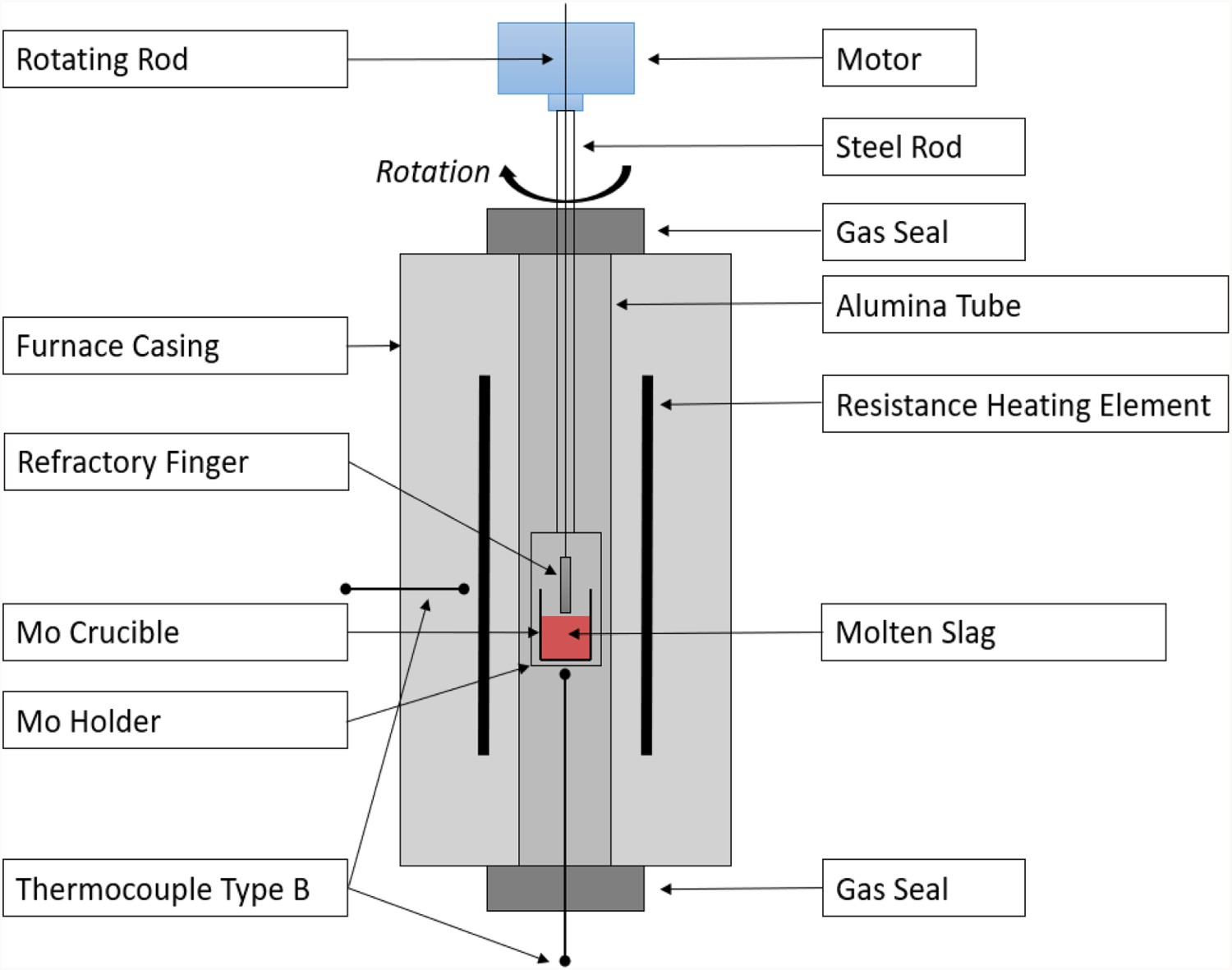
The crucible with slag and refractory finger were lowered to the hot zone before the furnace was sealed and evacuated using a vacuum pump. The furnace tube was flushed with argon and evacuated three times to remove oxygen. The furnace was heated at 2 K/min to the experimental temperature of 1700 K where it was held for 2 h for homogenization of temperatures. The refractory finger was lowered into the molten slag and rotated for 3 h at 100 RPM. After 3 h, the refractory finger was withdrawn from the molten slag before the furnace was cooled at 3 K/min to room temperature.
The wear of the refractory finger was examined in the cross-section of the finger and by measuring the weight and dimension before and after the experiment. The composition of the final slag was analysed to determine the amount of dissolved refractory and crucible material.
Results
Thermodynamic calculations
The thermodynamic calculations show clear differences in stability between the different refractory materials when in contact with the IronArc slag. However, the results are also affected by which software and database is used for the calculation. The calculated slag formation temperatures for the different refractory–slag systems and expected experimental results are summarized in Table 2.
IronArc slag
The IronArc slag has a composition of 90% FeO, 5% CaO and 5% SiO2 by weight. The equilibrium calculation for 100 g of this composition shows a slag formation temperature of 1420 K using the tcox8 database. In the FactSage™ calculations employing the Equilibrium module, the formation temperature of the slag is 1470 K, and at 1600 K, the system is entirely liquid. For the slag–refractory systems, some slag formation should be expected at this temperature range when the FeO forms an initial slag.
SiC refractories
The SiC refractory contains a significant amount of alumina as is shown in Table 1. The thermodynamic calculations for the SiC system with 90 g FeO, 5 g SiO2, 5 g CaO, 6 g Si, 11 g Al2O3, and 3 g C return significantly different results depending on database and calculation method. However, both the FactSage™ calculations with the FactPS, FT misc and FT oxid databases and the Thermo-calc® calculations using TCOX8 show that the solid olivine phase with high amounts of Si melts at 1300–1400 K and that a spinel phase with high amounts of Al is stable up to almost 1600 K. The phase distributions at different temperatures in TCOX8 and FactSage™ for the SiC experimental system are compared in Figures 2 and 3. Phase distribution along the temperature interval 1000–2000 K in FactSage™ calculations. Phase distribution along the temperature interval 1000–2000 K in Thermo-calc® calculation sin TCOX8.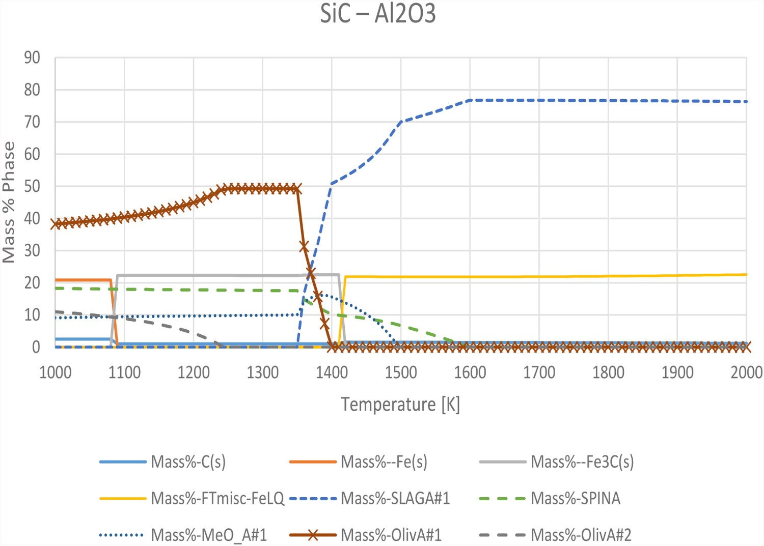
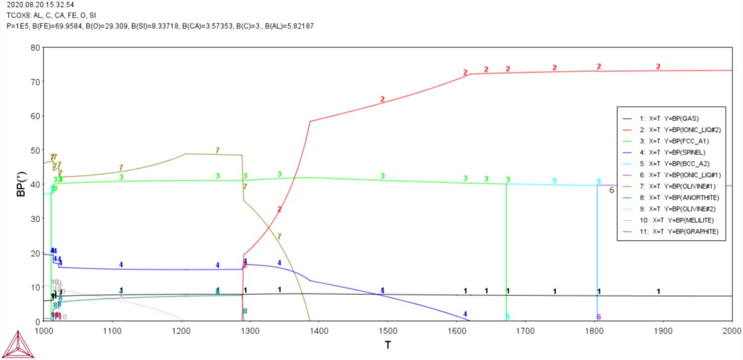
The main differences in the calculations are that FactSage™ predicts a significant amount of cementite from 1100 to 1400 K, which transforms to a liquid iron phase above the eutectic of 1420 K. Thermo-calc® and TCOX8 instead predicts significant amounts of metallic iron in the FCC and BCC phases up until 1800 K, as well as a steady amount of gas in the system. The TCFE9 database predicts the solid phases to be stable up to 1530 K, where some slag is formed. However, a metallic FCC phase high in Fe remains stable up to 1800 K. This discrepancy between the calculation methods casts doubt on the accuracy of the calculations in this system, which are most likely based on incomplete or wrong data in the databases.
MgO–C
The calculation results in the MgO–C system with 90 g FeO, 5 g SiO2, 5 g CaO, 1 g C, and 19 g MgO show similar results in the Thermo-calc calculations using the TCOX8 database and the FactSage™ calculations using the FactPS, FTmisc, and FToxid databases, with the TCFE9 database shifting the results to 300 K higher values. The solid phases are stable up to 1600 K after which they start to decompose to slag. However, at 1800 K, MgO is still present in the solid phases to a high degree, and the amount of MgO in the slag is very low. This indicates further stability at higher temperatures. However, the calculations show that carbon alloys with iron in this system to form a low melting temperature iron melt. This removal of the carbon from the MgO may reduce its structural integrity despite thermodynamic stability.
MgO–spinel
The calculation results for the MgO–spinel system with 90 g FeO, 5 g SiO2, 5 g CaO, 4 g Al2O3, and 16 g MgO are very similar in Thermo-calc® using TCOX8 and FactSage™ with FactPS, FTmisc, and FToxid database, with the TCFE9 calculations shifting the results to 300k higher values. Like the MgO–C calculations, the metallic oxide phases are stable to 1500 K after which they start to melt to a slag. The MgO is stable as a monoxide up to 1800 K, but most of the Al2O3 in the spinel is dissolved in the slag. This may compromise the structural integrity of the refractory brick.
Alumina spinel
The calculation results for the Alumina spinel system with 90 g FeO, 5 g SiO2, 5 g CaO, 18 g Al2O3, and 2 g MgO were very similar for the FactSage™ calculations with FactPS, FTmisc, and FToxid database and the Thermo-calc® calculations with TCOX8. However, TCFE9 shows significantly different results. The FactSage™ and TCOX8 calculations show that the FeO is stable up to 1550 K after which it rapidly melts. Spinel phases of mainly FeAlO, Fe2O3, and Al3O4 are also stable but in decreasing amounts with increasing temperatures, to be completely molten at 1750 K. At 1600 K, the slag contains 8% Al2O3 and 1% MgO which indicates that a lot of the refractory material is molten. This will most likely result in structural failure of the refractory brick, despite some spinel phases still being stable.
Cr2O3
The calculation results for the chromite system with 90 g FeO, 5 g SiO2, 5 g CaO, 1.5 g Al2O3, and 18.5 g Cr2O3 were very similar between FactSage™ calculations with the FactPS, FTmisc, and FToxid databases and the Thermo-calc® calculations with TCOX8 and show that a metal oxide phase with high amounts of FeO and 4.5% Cr2O3 is stable up to 1600 K. Additionally, a spinel phase with 75% FeCr, 5% FeAl, and 5% CrAl is stable up to 1650–1800 K after which it starts to slowly decrease in amount with an increased temperature. The slag starts forming already at 1450 K but does not reach high amounts until 1600 K when all the monoxide phases melt. At 1800 K, the slag phase only contains 4% Cr and 1% Al with a significant amount of FeCr Spinel still stable. This indicates that the refractory may survive in high temperatures if the FeCr Spinel can form a protective layer on the refractory brick.
ZrO2
The calculation results for the ZrO2 system with 90 g FeO, 9 g SiO2, 5 g CaO, 8 g Al2O3, and 8 g ZrO2 were very similar in the FactSage™ calculations with the FactPS, FTmisc, and FToxid databases and the Thermo-calc® calculations with TCOX8, but TCFE9 did not have proper support for calculations with zirconia oxides. The calculations show that slag formation starts already at 1300 K and at 1700 K the system is entirely liquid. At 1400 K, the slag consists of 50% ZrO2 which indicates very low stability in the refractory material.
Graphite
The calculation results in the graphite system with 90 g FeO, 5 g SiO2, 5 g CaO, and 20 g C show that graphite is never stable over the studied temperature range. The calculations in Thermo-calc® with the TCOX8 database predict significant gas formation even at low temperatures and a slag formation at 1400 K. The FactSage™ calculations with the FactPS, FTmisc, and FToxid database show that a liquid iron saturated with carbon is formed above the eutectic point at 1420 K.
Molybdenum in experimental systems
When 5 g of molybdenum were added to the thermodynamic calculation of the experimental composition in Thermo-calc® using the TCOX8 database, only very small changes could be seen in some of the refractory systems at equilibrium. All systems show slightly higher amounts of spinel phase at lower temperatures at the expense of other solid phases. In the MgO–spinel and AZS system, the slag formation temperature was increased by 20 K but is still significantly below the experimental temperature.
Expected experimental results
Summary of thermodynamic calculations
Mathematical modelling
The mathematical model results showed that the shear stresses on the refractory piece were highest in the corners of the rotating refractory rod and that the shear stresses in the refractory corners were directly correlated to the rotational speed.
In the 2D simulation, it was found that shear stresses of 5 Pa were produced, when rotating the refractory piece at a speed of 10 rad/s. This is equivalent to 95 RPM, which is an appropriate rotational speed to use in the experiments without introducing too much instability to the rotation system. This rotation produces a velocity of a 7 cm/s at the edges of the refractory finger, which is shown in Figure 4. Velocity profiles in 2D modelling of experimental set-up.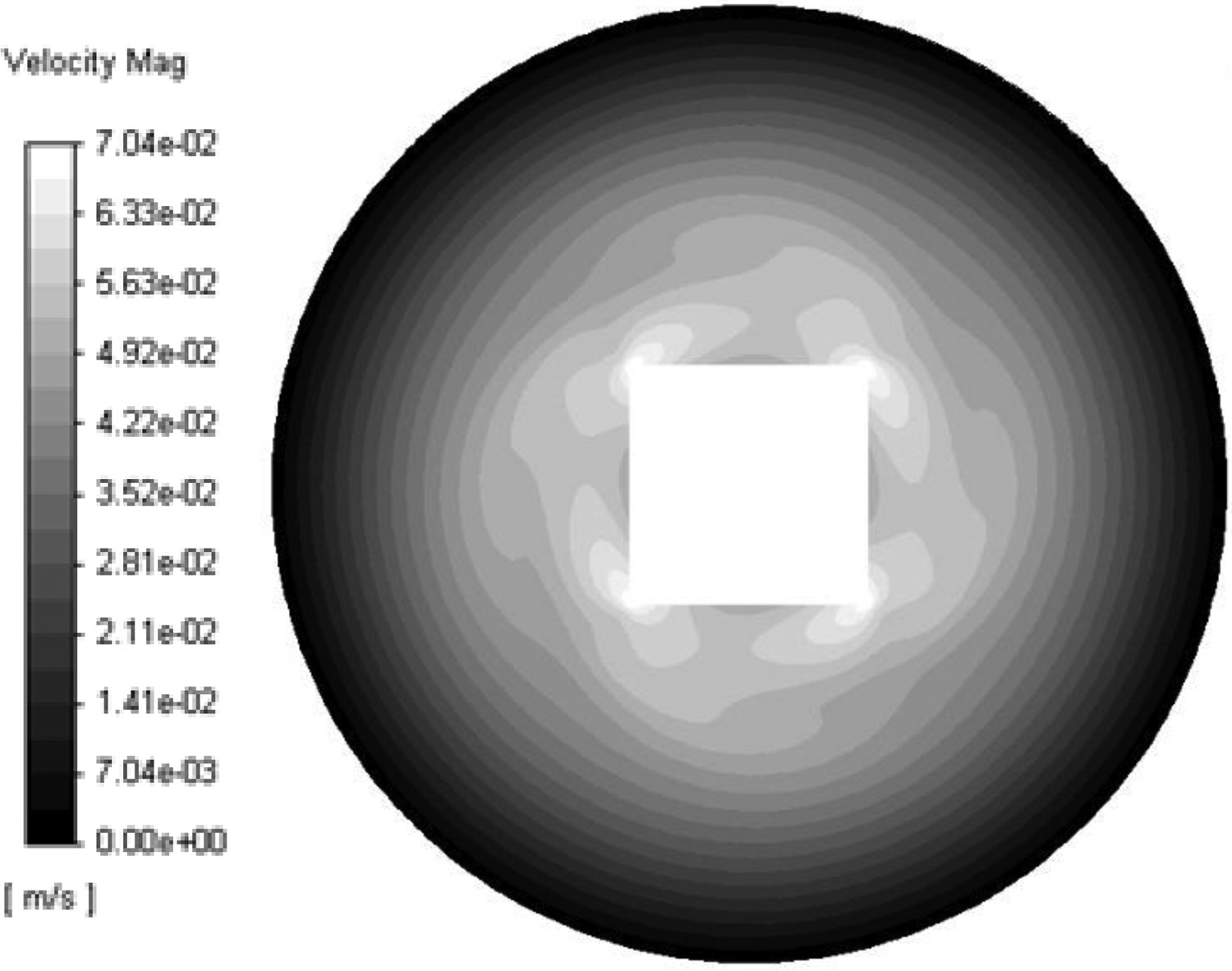
The 3D simulation was run with the same settings as the 2D simulation to study how the flow pattern develops differently in the upper and lower parts of the crucible. It was found that the movement of slag was very limited in the lower part of the crucible and at the lower end of the refractory finger, and that the edges of the refractory finger experiences the most wall shear stress. The velocity vectors and shear stress on the refractory in the 3D domain can be seen in Figure 5. Shear stress on impeller.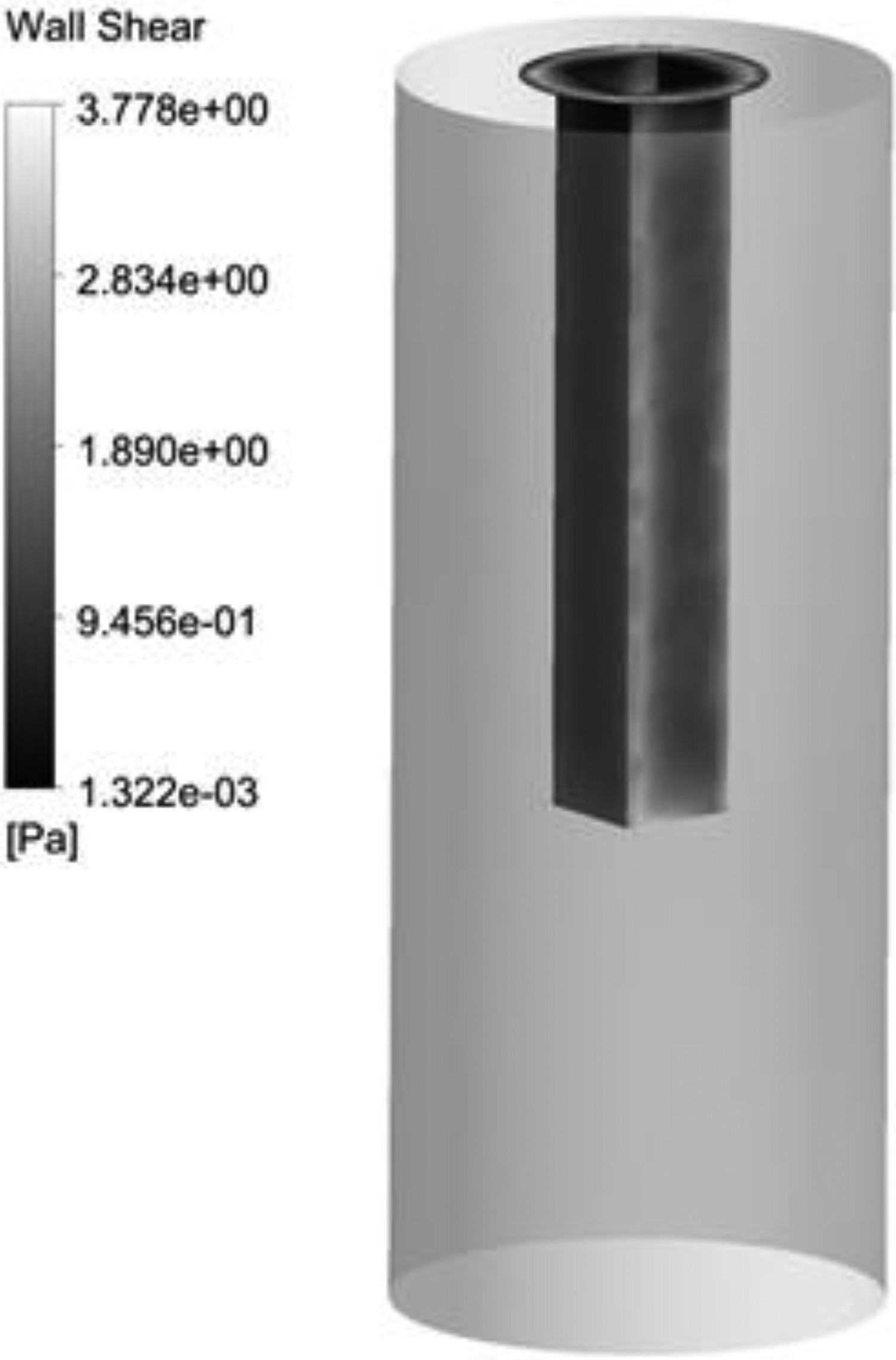
It was confirmed that the shear stress on the refractory piece is dependent on the viscosity used in the simulation. With increasing viscosities, the shear stresses increase significantly. Since the exact viscosity of the slag is not known, the same value as in the previous study of the flow in the IronArc slag runner of 0.1 Pa s is used. The expected shear stress of 5 Pa is also in the range which was measured in the previous study, where the average shear stress was 0.5 Pa and the maximum shear stress was 20 Pa [37]. Therefore, a rotation speed of 95 RPM could be used in the experiments.
High-temperature experiments
The results from the high-temperature experiments showed that the alumina spinel, Cr2O3, and AZS refractories completely dissolved in the slag during the experiment, as shown in Figure 6. The composition of the remaining slag, as seen in Table 4, shows increased levels of the refractory components. These results confirmed that the material is still in the system, but that it is dissolved in the slag. Refractory fingers before and after 3 h rotation in IronArc slag. EDS area analysis of adhered layer (Spectrum 1) and bulk refractory (Spectrum 2)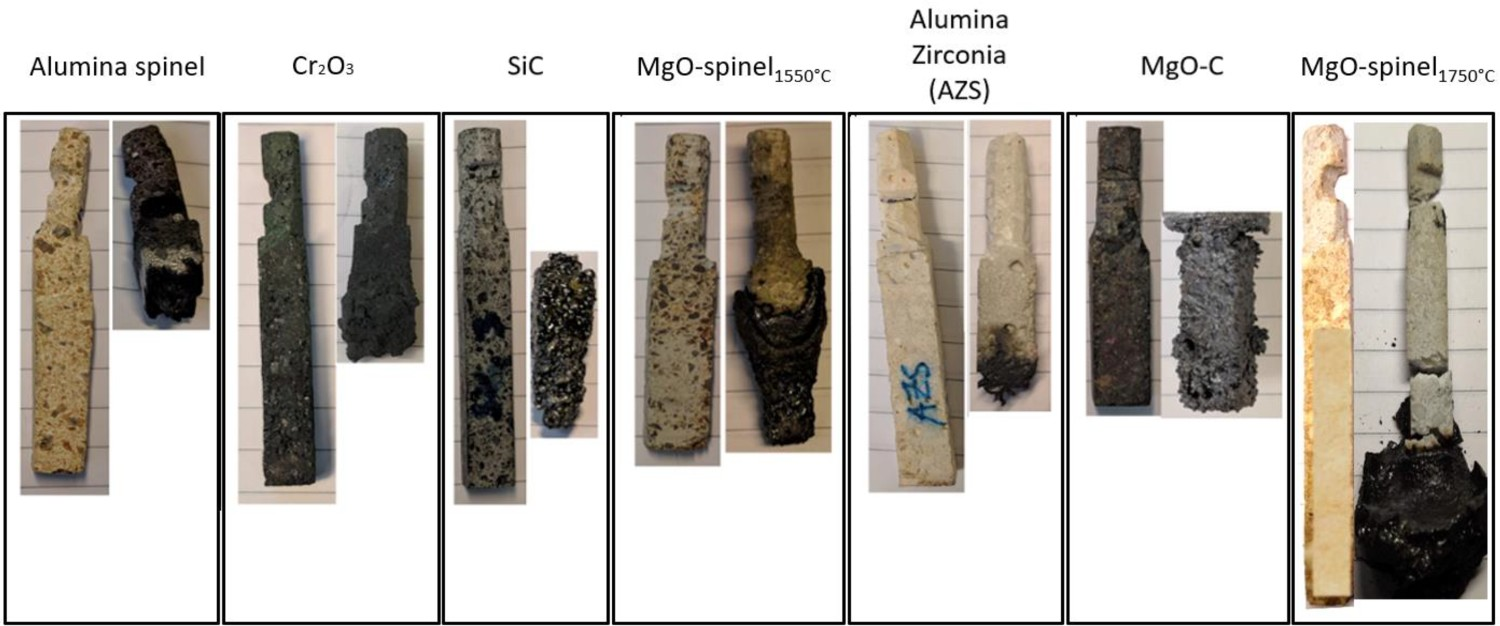
The SiC and MgO–C refractory fingers reacted with the slag during the experiments to form gas and a foaming slag. The gas and foaming slag expanded and escaped the crucible. An examination of the SiC and MgO–C refractories show only partially dissolved refractory fingers, but the escape of the slag from the crucible may have caused the refractory fingers not to be submerged for the entire experimental time, resulting in a lower wear. The remaining SiC refractory is covered in metallic blisters and the MgO–C piece is covered in a thin layer of metallic iron, which is adhered to the refractory fingers.
The graphite refractory finger reacted with the slag and reduced it to metallic iron. The molten iron formed an alloy with the Mo crucible which caused partial melting of the crucible, due to the lowered melting temperature of the Fe–Mo alloy. Part of the graphite finger remained in the solidified metal after the experiment, indicating carbon saturation of the liquid iron phase. This is in line with the thermodynamic calculations described previously.
The MgO–spinel1550°C refractory lost ∼17% in width and 2% in length due to wear but was still intact. When removed from the furnace, a significant amount of solidified slag was adhered to the refractory finger. This indicates a presence of a highly viscous slag phase, which formed in the vicinity of the refractory piece and adhered to it during cooling.
The MgO–spinel1750°C refractory finger broke during the experiment and was therefore not rotated for the entire experimental time in the slag. However, it was exposed to the slag corrosion until the furnace was cooled to room temperature. The pieces of the refractory finger recovered from the slag after the experiment were still intact, indicating a chemical resistance to slag corrosion.
The MgO–spinel1550°C and the MgO–spinel1750°C refractory pieces were analysed in LOM and SEM combined with EDS. The MgO–spinel1550°C cross-section in Figure 7(a) shows the porosity of the refractory brick and how the adhered slag is fused to it without resulting in a clear boundary. Also, SEM analysis was done where only a thin layer of adhered slag was present, as marked in Figure 7(a). The SEM image in Figure 7(b) shows the boundary layer to the left and the refractory to the right. The thickness of the adhered layer is ∼100 µm and an EDS determination of the marked spectra are presented in Table 4. Cross-section of MgO–spinel1550°C in close-up with refractory location marked with large rectangle and magnified area marked with small square (a) and 600× magnification (b).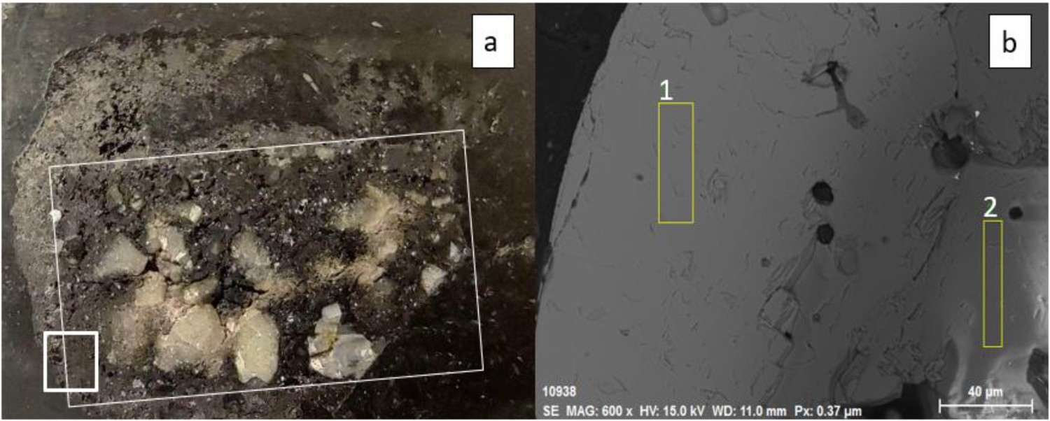
The oxygen content implies that all elements are bound as oxides in these areas and that these are mainly a mix of FeO x and MgO. The adhered layer is dominated by FeO x at a molar ratio of 3.5:1 as seen in spectrum 1 and inside the refractory piece MgO is abundant, but with some FeO x at a molar ratio of 1:6 as seen in spectrum 2.
The MgO–spinel1750°C cross-section in Figure 8(a) shows a dense refractory material surrounded by adhered slag, but with no clear boundaries between the slag and refractory as the outer parts of the refractory are dissolved. The SEM results in Figure 8(b) show the contact region (marked in Figure 8(a) with a white rectangle) with refractory on the top and slag with particles in the bottom of the image. The composition of the refractory, adhered material, and particles are listed in Table 5. Cross-section of MgO–spinel1750°C as close-up with refractory location marked with large rectangle and magnified area marked with small square (a) and 50× magnification (b). EDS area analysis of bulk refractory (Spectrum 5), adhered slag (Spectrum 6), and suspended metallic droplets (Spectrum 7)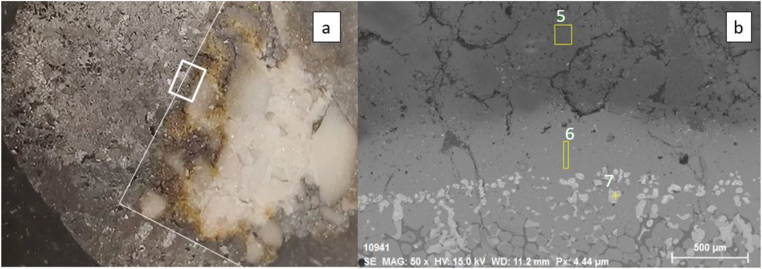
The high oxygen content in spectrum 5 and 6 indicate that oxides are present in the slag and refractory areas and that they contain a mix of FeO x and MgO. The adhered layer in Spectrum 6 is dominated by FeO x and MgO at a ratio of 2:1. This phase may have been molten during the experiments since the MgO–wüstite solid phase is only stable up to 1650 K according to the thermodynamic calculations. Inside the refractory piece MgO is abundant, but with some FeO x at a ratio of 1:8 as seen in Spectrum 5. The particles in Spectrum 7 are metallic and consist of mainly iron alloyed with molybdenum and low amounts of magnesium and silicon.
Slag composition before and after refractory finger experiments in wt-%
The dissolution of refractory material and crucible material into the slag causes dilution of the slag and thus lowers the relative FeO x content in the final slag. It is possible that some Fe was lost by alloying with the Mo crucible and that some SiO2 was vaporized during the experiment.
Discussion
The CFD simulation confirms similar shear stresses between the experiments and the numerical study of the IronArc slag runner. The experimental set-up will result in a more stagnant behaviour, since the renewal of slag to the reaction zone is limited, causing a saturated slag.
The high-temperature experiments show that none of the tested refractory materials were impervious to reactions with the slag. However, the MgO–spinel refractories are candidates for further research as they only experienced partial wear during the tests. The EDS results of the adhered layer show a significant amount of magnesium, which has diffused from the refractory. A mix of FeO x and MgO at a ratio of 2–3:1 without much other impurities indicates that magnesiowüstite is present. Also, the adhered material contains dissolved droplets at a fixed distance from the refractory. These were confirmed to be metallic, indicating a reduction of iron by the refractory or crucible material. The droplets also indicate that the surrounding slag is saturated in iron and that more magnesium diffusion through the magnesiowüstite layer is required for further dissolution.
The MgO–spinel1750°C refractory has higher sintering temperatures and higher purity materials than the other materials, which results in lower porosity and less surface area for reactions between slag and refractory. This reduced contact should slow down chemical reactions and give the MgO–spinel1750°C a greater wear resistance compared to the other refractories. When comparing Figure 8(a) with Figure 7(a), it is apparent that MgO–spinel1750°C is denser than the MgO–spinel1550°C. However, according to both the slag composition and the SEM analysis, the amount of MgO in the slag is higher in the MgO–spinel1750°C experiment than in the MgO–spinel1550°C experiment. This indicates that the MgO–spinel1750°C has decomposed more than the MgO–spinel1550°C when being in contact with the slag, this is likely due to the extended exposure time for the MgO–spinel1750°C caused by the breakage during the experiment.
In industry, the tested MgO–spinel samples are known to perform well in contact with steel, but not with slags. In the current experiments, the interaction with Fe-rich slags appears to be beneficial to the refractoriness of the bricks, as they did not completely dissolve in the experiments. However, the MgO–spinel samples will likely not perform well in the industrial scale of the IronArc process since in the experiments the MgO–spinel samples experienced partial dissolution after only 3 h. Such dissolution is likely to continue as the system approaches equilibrium, as according to the equilibrium calculations, liquid phases are formed at the experimental temperature.
The SiC and MgO–C experiments produced significant amounts of gas from reactions between the refractory and slag. The gas foamed the slag which escaped the crucible and shrouded the experimental results. The formation of gas in the MgO–C refractory system may be a result of the reaction which forms dense layer MgO in BOF ladles, but without sufficient oxygen in the system, the magnesium gas will not reform to MgO [24]. When carbon is removed, the structural integrity of the refractory is instead reduced, causing an increased susceptibility to wear. In industrial applications, a significant gas formation is not a sustainable solution. This disqualifies carbon-containing refractories to be used in the IronArc process.
The graphite rod withstood the experiment by reducing the slag to metal, but this will not work in an industrial setting. In a continuous process, the liquid slag will be replenished continuously and never reach equilibrium with graphite. This will cause a significant wear of the graphite lining unless it is used as a device for heat transfer to form a freeze-lining. The graphite performed as expected with a slight gas formation and a reduction of the slag to a metal-alloy in equilibrium with graphite.
The ZrO2 and alumina spinel refractories were completely dissolved in the experiments, as predicted by the thermodynamic calculations. The thermodynamic calculations showed that SiC was not expected to form significant amounts of gas. However, the foaming slag is evidence that a significant gas formation occurred. For the MgO–C refractory, the gas formation was not expected, but a stable solid phase after the experiment was expected. For the SiC refractory, some stable phases were found after the experiment, even though the calculations predicted that a complete dissolution would take place.
The Cr2O3 refractory performed much worse than predicted. Only a partial dissolution was expected by the thermodynamic calculations, since the FeCr spinel phase was stable at high temperatures. However, the refractory finger completely dissolved in the experiment. The low-temperature formation of slag at 1470 K may be an indicator that dissolution will be prominent.
The experimental results were reasonably well predicted by the thermodynamic calculations done in Thermo-calc® using the TCOX8 database and from calculations using FactSage™. However, the supplemental calculations performed with the TCFE9 database show that there are significant differences in the thermodynamic calculations depending on database and software used.
The thermodynamic study highlights the importance of choosing the correct database and calculation method, as they have significant impacts on the predicted formation temperatures of the phases. The thermodynamic calculations were not accurate for all the studied systems, which is most likely caused by the lack of good experimental data in the databases. However, the thermodynamic results are still useful and give indications to what refractory materials are promising for the experimental studies, but they cannot replace experimental work.
Regardless of accuracy of the databases and calculation method of the thermodynamic calculations, some differences in refractory wear between thermodynamic prediction and experiment will occur and are dependent on a few factors. The lowering of the refractory fingers into the molten slag will introduce some thermal stresses in the refractory fingers, which may cause a weakening of the refractory. Additionally, the refractories used for the experimental study are industrial grade with porosities and impurities, which is not considered in the thermodynamic calculations.
The wetting properties and reaction kinetics are not included in the thermodynamic calculations, which decrease the accuracy of the results. By using synthetic lab-grade refractories, the experimental results would likely be closer to the thermodynamic results, but further away from the industrial conditions.
The refractories may also dissolve because they have too low thermal stabilities. The oxidizing conditions cause carbon and other binder material to leave the bricks, leaving the particles of refractory oxides more susceptible to erosion by movements in the system. For example, in the MgO-based refractory experiments, parts of the brick were dissolved, even though MgO is listed as a stable phase at high temperatures in the thermodynamic calculations. These results suggest that pieces of the more resistant MgO are spalled away from the refractory and left as discrete particles in the slag rather than dissolved when the carbon or spinel phases are removed.
The slag composition shows that small amounts of Mo from the crucible during experiment dissolves in the slag. However, such low amounts of molybdenum oxides are unlikely to affect the stability of the refractories. In the EDS analysis of the MgO–spinel refractories, the Mo content in the slag surrounding the refractory is in the range of 1 wt-%, much lower than measured in the bulk slag. Using an iron crucible would have been preferable to simplify the equilibrium equations, but a change of crucible is not expected to have a significant impact on the results. When 5 wt-% Mo was added to the experimental systems in thermodynamic calculations using Thermo-calc® and the TCOX8 database, the amount of spinel phase increased slightly in all systems at low temperatures and equilibrium conditions, but with negligible difference at higher temperatures. In the MgO–spinel and AZS system, the slag formation temperature was increased ∼20 K at equilibrium conditions, but the predicted experimental behaviour is unaffected as the new melting temperature is still significantly below the experimental temperature. With lower amounts of Mo, considering non-equilibrium conditions in the experiments, the effect will be much smaller. These results combined with many years experience of using Mo crucibles suggest that the use of Mo crucibles instead of iron crucibles does not have a significant effect on the results of the experiment.
Possible errors in the experimental procedure include breakage of some refractory rods, which hindered proper evaluations of those experiments. The accuracy of the temperature control is good and is accurate to +−5°, according to thermocouple and set-up errors. The amount of oxygen in the system is not known, but the atmosphere is controlled. The initial atmosphere is flushed away with high purity argon 5.0 and during the experiment, a low flow of argon protects the experiment from outside influence. The oxygen content in the system is presumed to be controlled by the oxygen added through the refractory and slag and should be constant during the experiment but may change slightly if large amounts of gas is formed by chemical reactions. The temperature uncertainty may affect wear slightly, but the temperature control is not very precise in industry either.
For further studies of possible refractories for an FeOx-rich slag, the thermodynamic evaluation procedure can be utilized as thermodynamic calculations give useful indications of the refractory behaviour in the high-temperature experiments. The effect of sintering temperature and porosity on the wear resistance of the refractory fingers should be studied further.
Conclusions
High-temperature experiments have been performed by submerging and rotating refractory bricks in a slag with 90 wt-% FeO to study their resistance to dissolution. The experimental set-up was studied in CFD to ensure correct rotation speed and shear stresses on the walls. The thermodynamic equilibriums of the experimental systems were calculated in Thermo-calc® using the TCFE9 and TCOX8 database as well as in FactSage™ using the FactPS, FTmisc, and FToxid databases.
From the present study, it is confirmed that metallurgical slags rich in FeO x are very corrosive to most conventional refractory materials at ironmaking temperatures. Refractory materials containing significant amounts of carbon react with the slag and form gas, which contributes to a formation of foaming slag and a removal of carbon from the refractory material.
The thermodynamic calculations can be used for screening of promising refractory materials for further tests as the formation temperature of slag and its composition at varying temperatures was found to be an indicator of the wear resistance of the refractories to the studied slag. The calculation method and database used for the thermodynamic calculations was found to have a significant impact on the results from the calculations.
None of the tested refractories showed clear resistance to the slag, but further work must be done to determine if any can be considered for industrial use. Overall, the MgO–spinel type refractories showed the most resistance towards the studied slag due to the stability of MgO and possible formation of a protective magnesiowüstite layer. Therefore, they should be studied more in-depth in the future.