
Abstract
Effect of a swirling flow SEN (submerged entry nozzle) outlet design on the multiphase flow and heat transfer in a mould was investigated by using numerical simulation. It was found that different SEN outlet designs could form different flow patterns and temperature distributions on the upper of the mould. The enlarged outlet SEN design had an effect to decrease the horizontal velocity of liquid steel flowing out the SEN outlet, reducing the steel flow velocity towards the solidification front. Although a higher velocity was found near the slag/steel interface with the enlarged outlet SEN, but the turbulent kinetic energy was lower. The reason was that less circulation flows were formed in the region of the mould top. The weak horizontal flow towards the solidification front with the enlarged outlet SEN induced lower wall shear stresses, at the same time it also formed a lower temperature distribution near the solidified shell.
Introduction
During continuous casting process of steel, the liquid steel flows from the tundish to the SEN (submerged entry nozzle), then to the mould for solidification. In the mould, the liquid steel is covered with a slag layer on the top to lubricate the solidified shell, to protect the steel from air reoxidation and to absorb non-metallic inclusions. It is very important to find out how the liquid steel interacts with the slag layer and how to optimize the flow pattern to get a better control on this multiphase flow combined with heat transfer in the mould.
In order to improve the multiphase flow pattern and heat transfer in the mould, there were a large number of aspects studied by the researchers. First of all, the structure of SEN could be modified to satisfy certain demands, for example, the SEN with straight or bifurcated outlet [1,2], SEN port design with different shapes, angles or thickness [3–10], and different SEN immersion depth [3,4,6,11]. Then, some researcher used argon to be injected to the SEN to improve the continuous casting process in order to avoid the nozzle clogging, reduce the steel reoxidation and help the inclusion to float up to the slag. Moreover, EMBr (Electromagnetic Braking) [12,13] and M-EMS (Mould Electromagnetic Stirring) [8–10] were vastly studied to change the flow pattern of steel in mould. With this modification of casting process, the flow pattern could be improved a lot and a more calmer liquid steel flow with lower fluctuation could be gained to achieve a more efficient way to remove the heat in the mould. Based on this work, the swirling flow SEN was utilized to further optimize the flow pattern. The new design of SEN has been investigated during the last few years and it has been proved that it could improve the steel flow in mould. The significant improvement with this method was that it could generate the rotational flow before the steel flows into the mould. First of all, the heat and mass transfer near the meniscus could be remarkably activated [14–17], then a more uniform velocity distribution could be obtained if a short distance from the SEN outlet was used [14–16]. Moreover, the penetration depth of the SEN outlet flow was remarkably decreased in a billet mould [14,17]. Some results from the industry showed that the steel product quality could be increased significantly and less clogging of the SEN side ports happened with the help of the swirling flow SEN [18].
Some researchers have investigated to use the swirling flow inside the SEN to form a more stable flow. A twist-shape swirl blade [14–18] was inserted into the SEN to generate the swirling flow for the continuous casting process, but there was still some risk of clogging with a long casting time because of the inclusion deposition on its surface. Another method was the electromagnetic stirring method [19–22], which could be implemented around the SEN for continuous casting process. However, the high cost of equipment and electricity were drawbacks of the electromagnetic stirring method, which might lead to an increase in the steel production cost. A new method was proposed to generate swirling flow in a SEN simply by using a cylindrical tundish design [23–27]. It was studied by both mathematical and physical modelling [25]. This new tundish design could also improve the steel flow characteristics and temperature distribution in mould [26]. The immersion depth of SEN was also investigated for decreasing the interfacial velocity and reducing the risk for the slag entrainment [27].
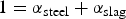
Previous research work about the swirling flow tundish design has covered on the steel–slag flow, temperature distribution and the steel flow in the vicinity of the solidified shell in mould [26]. Based on the work of investigating the effect of the immersion depth of the swirling flow tundish SEN on the multiphase flow and heat transfer in a billet mould [27], a different SEN design with an enlarged outlet was investigated in this paper. This new design aimed to be compared to the original straight SEN to investigate its influence on multiphase flow and temperature distribution in mould. The behaviour of steel–slag interface was simulated by the VOF (volume of fluid) method, and the temperature distribution in the mould was obtained by solving the energy equation. The comparisons of the steel flow characteristics, steel–slag interface velocity, mould fluctuation, and temperature distribution in the mould, with a straight SEN design and with an enlarged SEN outlet design, were investigated.
Model description
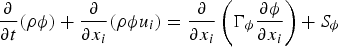
Mathematical models with different SEN designs to describe the multiphase flow and heat transfer in a billet mould have been developed. The geometry and the dimension of the billet mould and the SEN are shown in Figure 1. Geometry of the casting mould, (a) Straight SEN and (b) Enlarged outlet SEN.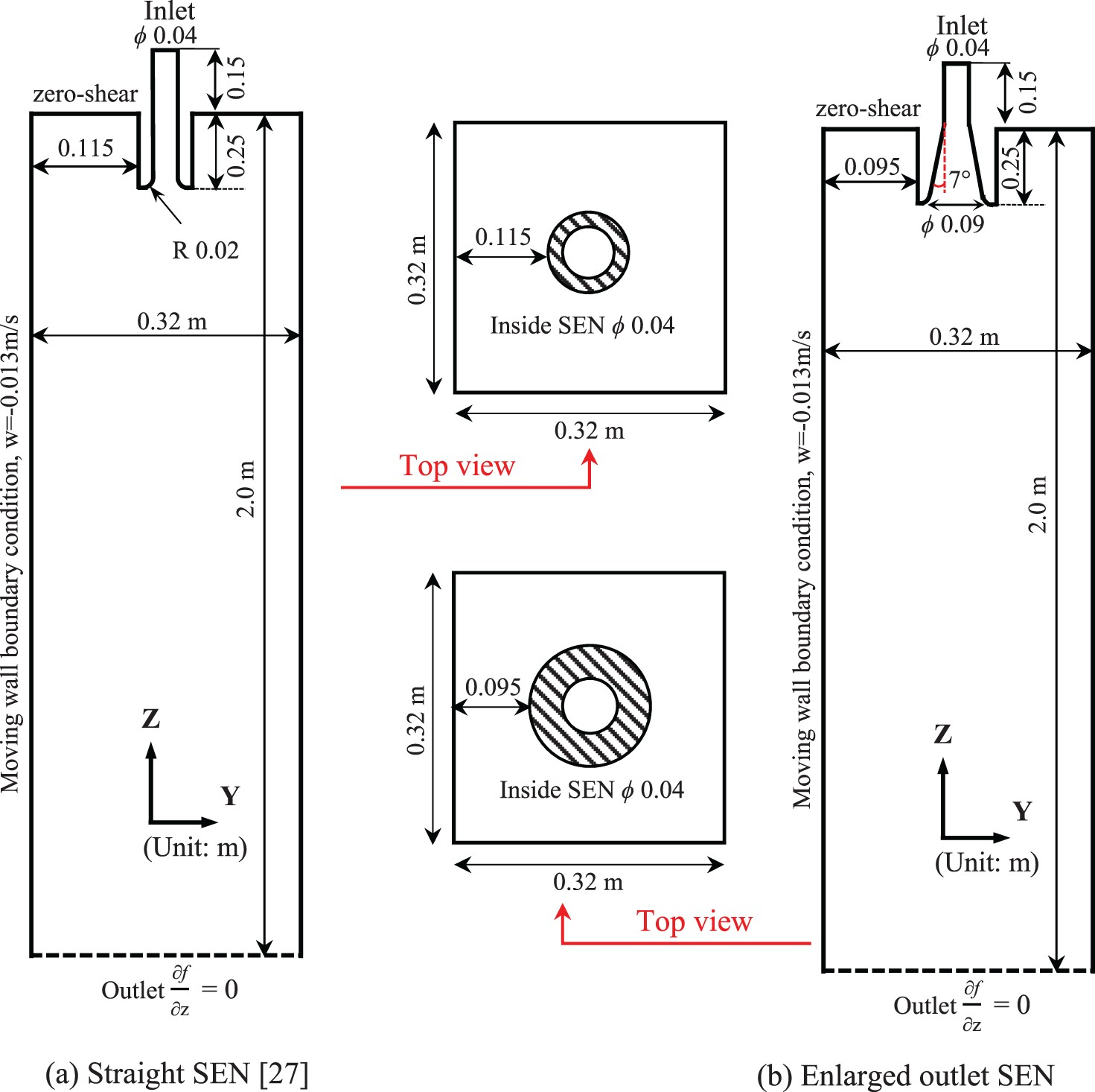
Model assumption
The numerical model was based on the following assumptions: Molten Steel and slag behaved as incompressible Newtonian fluids; Solidification in the mould was not considered; Since the temperature difference in the mould is only 30 K, from 1788 to 1818 K, a constant molecular viscosity for steel and slag was assumed. Within this temperature range, the viscosity change was not large [10]; The SEN wall was assumed to be a smooth wall.
Transport equations
When considering a general variable 


VOF model was used to track the steel–slag interface [29]. The mixed material properties in the grid cell as shown in Equations (2) and (3), where the interface exists, were used in the momentum equation:


At the first step of the simulation process, the realizable k-ε turbulence model coupled with the Enhanced Wall Treatment model was used in order to produce an initial flow field [29]. Then, the RSM (Reynolds Stress Model) model combined with the Stress-Omega sub-model was used to simulate the steel flow. The Stress-Omega sub-model has been proved to be siutable for modelling flows over the curved surfaces and swirling flows [29].


Thermal properties of the steel and slag.
Boundary conditions
At the inlet of the SEN, velocity profile of swirling flow was set on the cross section of the cylindrical tundish SEN [25]. This steel flow velocity at the inlet in Figure 1(a) could be found from a previous study [26]. The SEN wall has a non-slip boundary condition. A zero-shear slip wall boundary condition was used at the mould surface. A moving wall boundary condition with the velocity of 0.013 m s–1 in Z direction was used on the mould wall to stand for the movement of the solidified shell during the casting process. The normal gradients of all variables were set to zero at the mould outlet. A constant steel temperature of 1818 K was used at the inlet, and a constant temperature of 1788 K was imposed on the solidified shell. An adiabatic condition was used both at the SEN wall and at the free surface.
Solution method
The commercial software ANSYS FLUENT 18.0® was used in this study. The numerical simulations were carried out based on around 1.4 million grid cells to guarantee the grid-independent solution. The total number of cells was around 1.4 million after a mesh sensitivity study for all the simulations. In the near-wall region, the mesh was refined with the y + value of the first grid layer around 1. The PISO (Pressure-Implicit with Splitting of Operators) scheme was used for the pressure-velocity coupling. Moreover, the PRESTO (PREssure STaggering Option) method was adopted to discretize the pressure. The governing equations were discretized using a second order upwind scheme. All the residuals of dependent variables were set to be smaller than 1 × 10⁻³ at each time step.
Results and discussion
As mentioned above, the realizable k-ε model with an Enhanced Wall Treatment was used for the first 75 s, then it was switched to RSM model as an initial condition furtherly to 125 s for a developed flow field. The fluid flow and heat transfer in the mould with different SEN geometries were analysed and compared in the following.
Steel flow phenomena
Figure 2 shows the steel flow path in the mould with different SEN outlet design. A similar steel flow pattern in mould was obtained for different SEN designs. Steel flowed into the mould along the periphery of the SEN which is in 360°, and moved towards the solidified shell due to the swirling flow effect. After the steel stream reached the solidified shell, the majority of the steel flowed downwards along the solidified shell with a horizontally rotational flow momentum. A small part of the steel moved upwards to the meniscus. Therefore, with a swirling flow SEN, high-temperature steel was uniformly distributed towards the solidified shell, which was good for the dissipation of the steel superheat. When the enlarged outlet SEN was used, steel flow direction was more downwards compared to the case of a straight SEN. Comparison of steel flow paths in mould.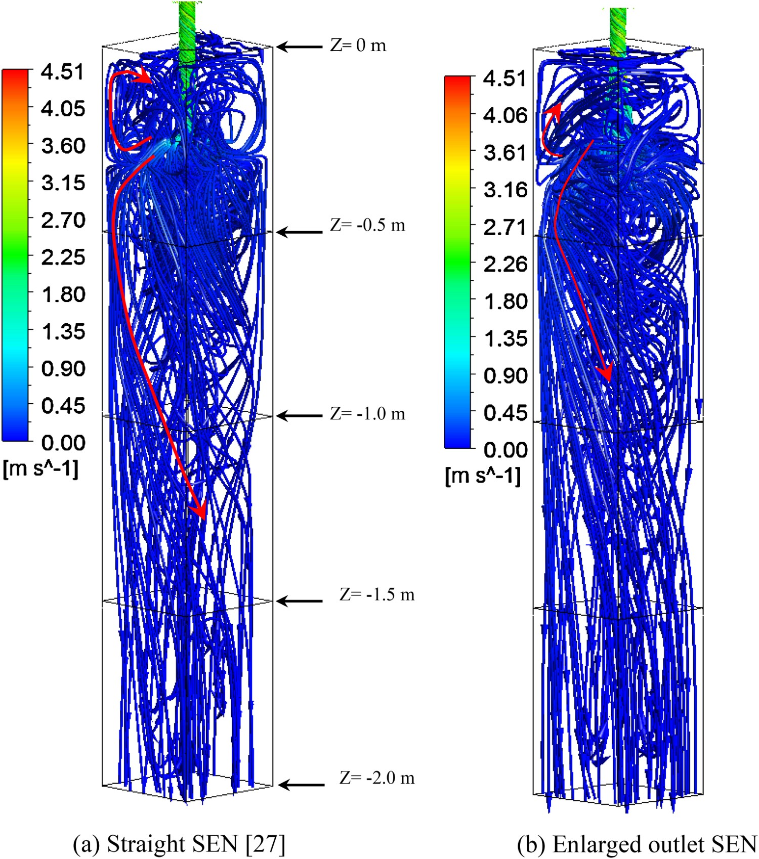
Figure 3 shows the velocity on the vertical plane located at the middle of the mould for different SEN designs. Generally, steel moved downwards at the region near the solidified shell and it flowed upwards in the centre of the mould. The flow difference induced by the enlarged outlet SEN was mainly located in the upper part of the mould. Specifically, the region with the steel flow velocity higher than 0.2 m s–1 was larger when the enlarged outlet SEN was used. This region was located in the mould centre and just below the SEN outlet. However, the flow region with a velocity higher than 0.05 m s–1 became smaller in the whole mould, compared to the case of a straight SEN. This might be due to that the rotational steel flow was dissipated by the nearby steel when the SEN undergoes an expansion. However, in the straight SEN case, steel kept a strong rotational momentum and suddenly moved out the SEN towards the solidified shell. Therefore, it could be seen that steel flowed more horizontally towards the shell and the steel flow near the solidified shell was more intensive on the top 1 m of the mould, compared to the enlarged outlet case. This higher flow velocity also induced a larger upwards flow in the mould centre. In addition, due to the weak horizontal flow from the enlarged outlet, the upwards flow became weak as shown in Figure 3(b). This led to a low velocity in the region near the meniscus. Steel flow velocity and flow direction in the vertical middle plane of the mould. (Arrows are the steel flow directions).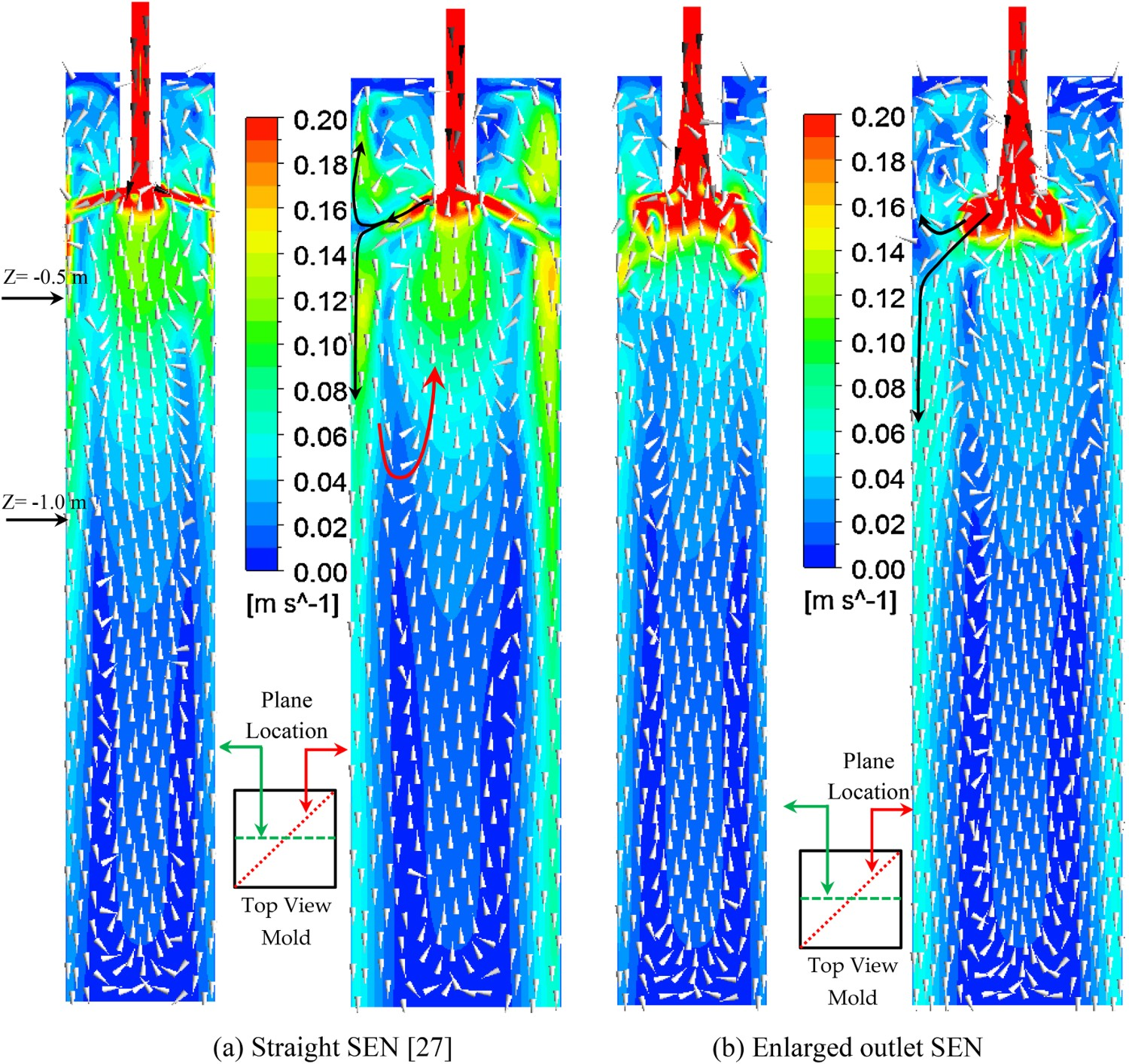
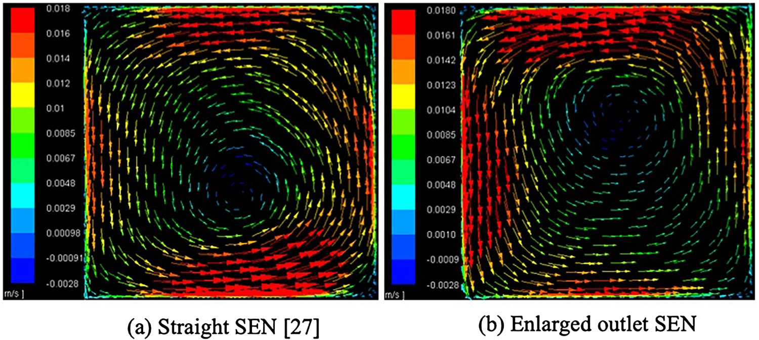
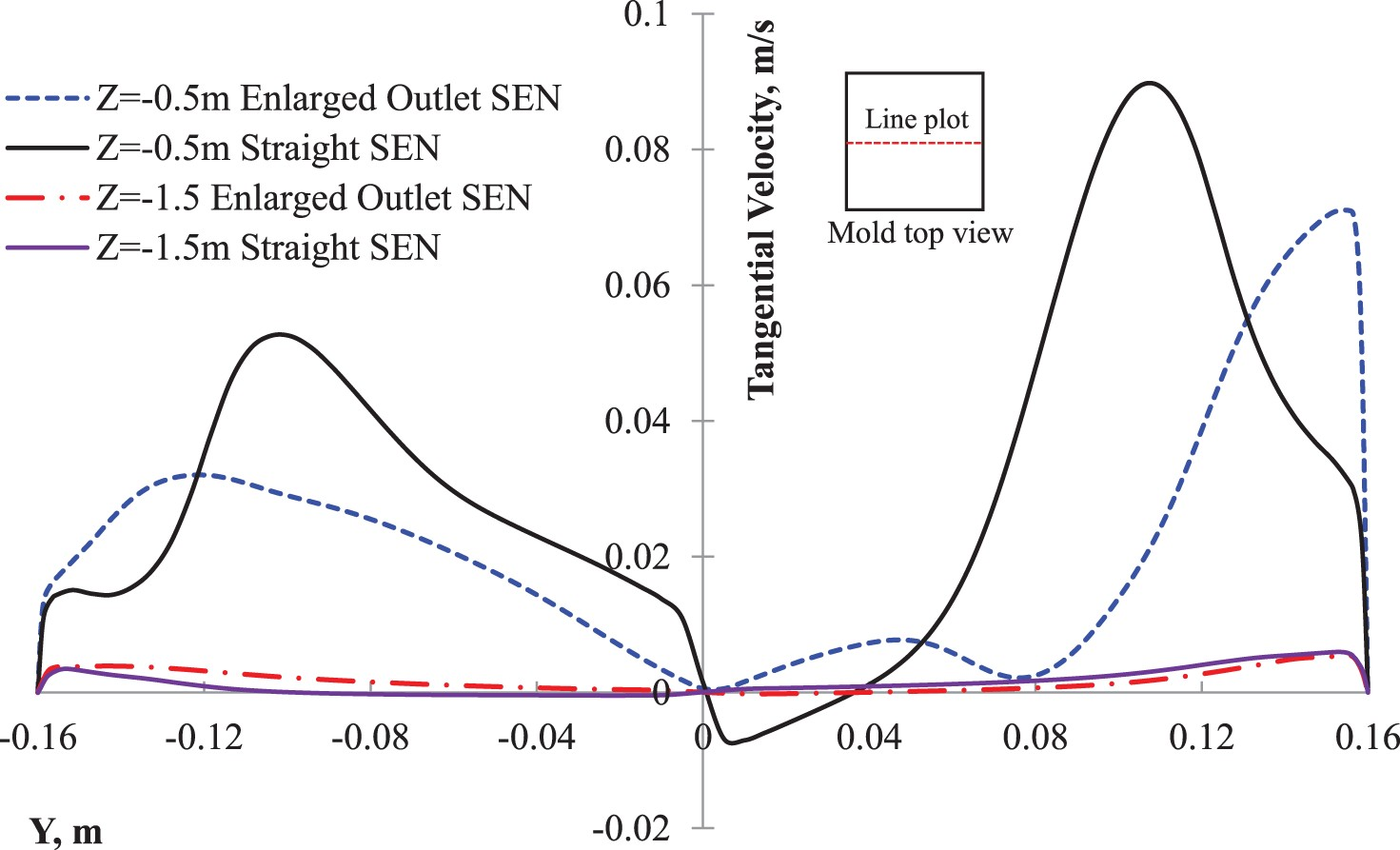
Figure 4 shows velocity distributions on different mould cross sections of the mould. Figure 4(a) shows that the maximum velocity with a straight SEN is larger than that with an enlarged outlet SEN at the steel/slag interface. A similar situation was found in Figure 4(b), which was 10 cm below the mould surface. This means that the steel flow in the mould top was more stable with an enlarged SEN outlet. Figure 4(c) shows the flow pattern on the cross section with 5 cm below the SEN outlet (0.3 m below the mould surface). It could be seen that in the straight SEN case, a high-velocity region was close to the solidified shell while it was still located in the centre of the mould in an enlarged outlet SEN case. As previously mentioned, this was due to the different horizontal flow velocities and flow angles after moving out SEN for different SEN designs. Figure 4(d) shows that the velocity near the solidification front is higher for the straight SEN case. Figure 4(e,f) shows that the flow fields were becoming developed with a high downwards velocity near the solidified shell and a high upwards velocity in the centre of the mould. The flow direction could easily be found from Figure 3. Figure 5 shows the tangential velocity distribution on the mould cross section with the mould depth of 1 m. It could be seen that a rotational steel flow pattern was obtained. High tangential velocity was located at the solidification front, and the maximum tangential velocity could reach 0.018 m s–1 near the solidified shell which was a similar value for both cases. The magnitude of the tangential velocity along different horizontal lines in different depths could be found from Figure 6. It was found that for both cases, the maximum tangential velocity decreased when the steel moved downwards. The high tangential velocity region was located near the solidification front. In addition, at the mould depth of 1.5 m, the rotational steel flow velocities were similar for both cases. Velocity distribution at different cross sections of the mould. Velocities on different cross sections of the mould at mould depth 1 m. Tangential velocity distribution along different horizontal lines in different mould depths.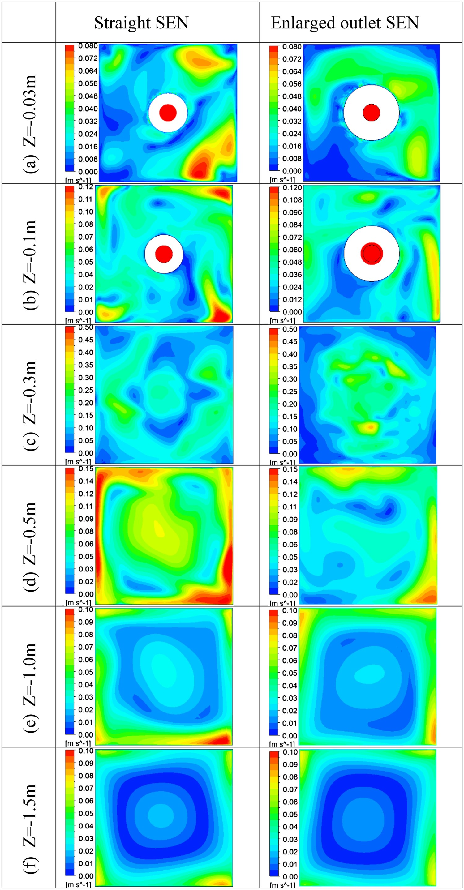
Steel/slag interface phenomena
The liquid steel flows from the tundish to the mould to be solidified from a high-temperature to a low-temperature state for subsequent processes. With the help of the swirling flow from the tundish, the impingement jet flow can be offset compared to the flow in a conventional casting process [26]. The swirling flow made the liquid steel flow towards the solidification front, which resulted in a larger region of activated steel flow and heat transfer near the meniscus [26]. However, a large steel flow velocity near the meniscus region also illustrates a high risk of the slag entrainment. Therefore, the new design SEN with an enlarged outlet was applied to investigate its influence on the interfacial flow stability.
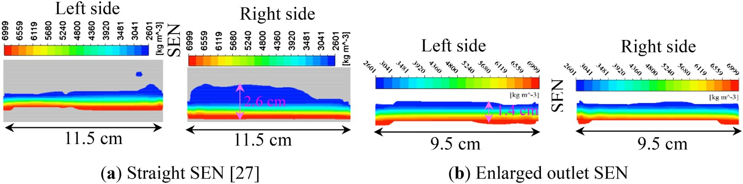
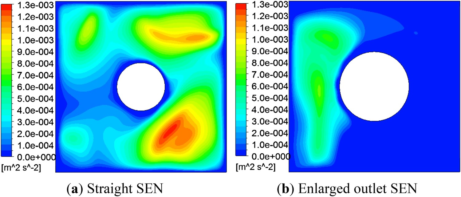
Figure 7 shows the steel/slag interface and the flow pattern in mould for different SEN designs. It could be seen that both these two SEN designs generated strong swirling flow and induced a circulation flow in the mould as well. However, a part of the liquid steel flowed upwards from the straight SEN outlet to form a circulation flow above the SEN outlet and near meniscus. This also resulted in a more active meniscus flow that could be proved by the iso-surface of the slag where the density of 2601 kg m–3 was plotted (the pure slag has the density of 2600 kg m–3). The liquid steel from the enlarged outlet SEN mainly flowed downwards to form the circulation flow under the SEN outlet and in a lower position compared to that by the straight SEN. There were also some smaller circulation flows above the SEN outlet, but they were much smaller compared to the circulation by the straight SEN and it would not push more liquid steel directly to the slag surface. VOF model cannot predict the sharp interface of two phases. Instead, a mixing region was predicted, and this mixing region did not mean that steel and slag were well mixed in reality. However, the thickness of the mixing region reflected the intensity of a steel/slag mixing. Figure 8 shows the enlarged view of the thickness of the steel/slag mixing region. It can be seen that the predicted maximum thickness of the mixing region decreased from 2.6 cm with the straight SEN to 1.4 cm with the enlarged outlet SEN. This means that the interface became more stable compared to the interface in the straight SEN case. Figure 9 shows the distributions of turbulent kinetic energy on the cross section of the interfacial region of the mould. It could be seen that the turbulent kinetic energy was much lower when the enlarged outlet SEN was used. This means the velocity fluctuation along the steel/slag interface was much smaller and this could also be reflected from the thickness of the steel/slag mixing region in Figure 8. In the case with M-EMS, the level fluctuation was found to be increased [10,30]. The meniscus surface had a swirling flow and the meniscus level rose near the bloom strand wall and sank around the SEN wall, which showed an inclined steel/slag interface [31]. Sometimes, a vortex formation near the SEN wall was found with M-EMS [32]. Therefore, the mould level fluctuation should be considered to make it as low as possible when the swirling flow is applied. The design of enlarged outlet SEN could decrease the fluctuation of interface and obtain a more stable meniscus compared to the original straight SEN design when a swirling flow inside the SEN was produced. Steel/slag interface with steel flow vectors. Enlarged interface region in Figure 7 with a density range from pure slag to pure steel. Turbulence kinetic energy distribution on the cross section of the mould.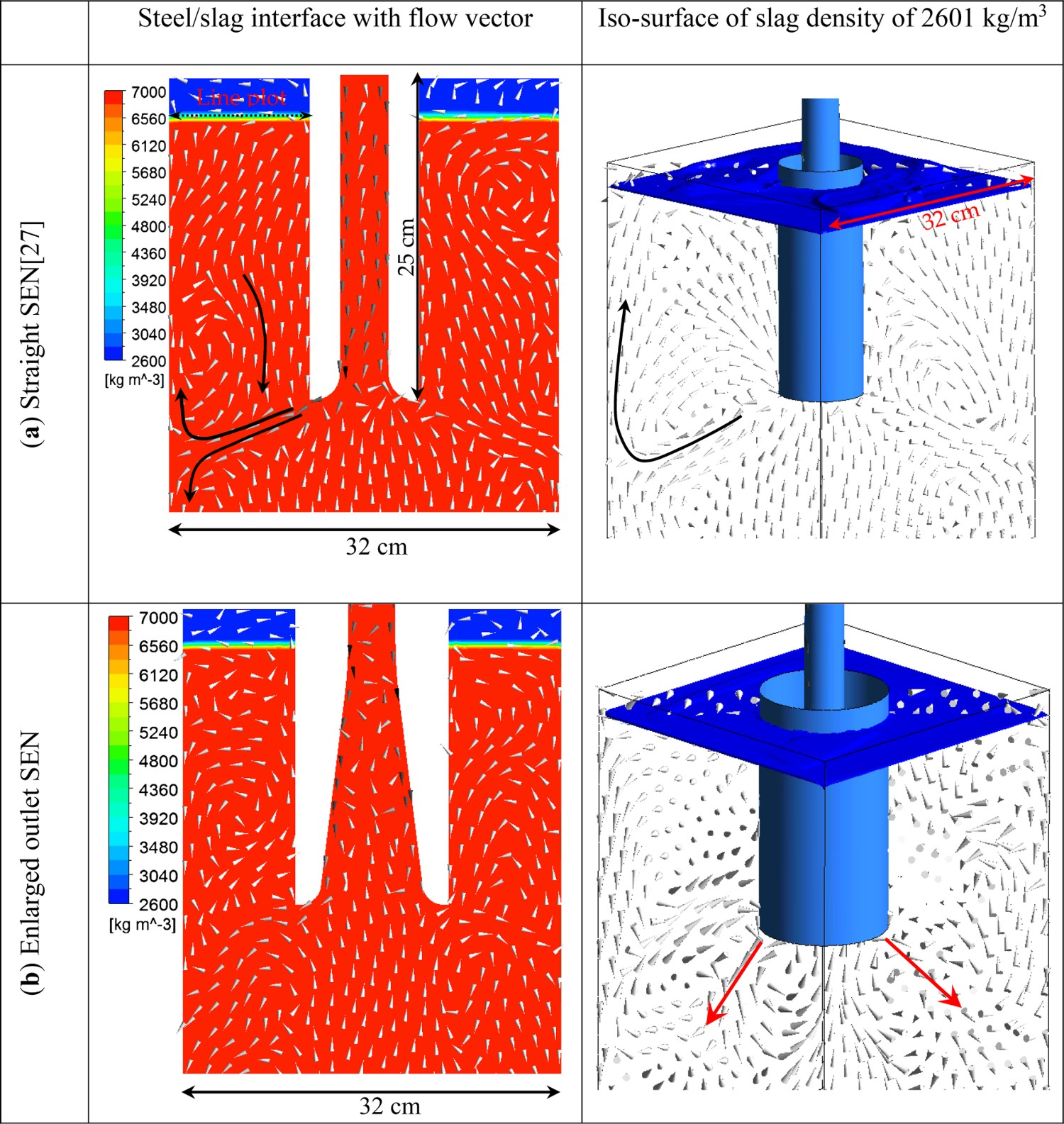
Another factor to judge how stable the meniscus is whether the fluctuated meniscus will entrain the slag into the liquid steel. According to previous research [33], the slag entrainment into liquid steel may occur when the Weber number is greater than 12.3. The Weber number can be defined as: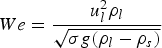


Temperature field
Liquid steel flows into mould for the final solidification, where the temperature drops from nearly 1800 K to several hundred Kelvin. However, the temperature distribution could be quite different with different types of SEN designs, and the temperature distribution could also affect the solidification structure which in turn determines the product quality. The design of SEN with swirling flow was a good option for accelerating the steel superheat removal [26], which was beneficial for the formation of equiaxed crystals. Figure 10 shows the temperature distribution in the mould with different SEN outlet designs. With the help of the swirling flow in both of these two SEN designs, the temperature increased near the solidified shell as well as the temperature gradient there, while the core temperature of the billet was low. The main difference between these two designs on temperature distribution appeared at the region near the SEN outlet. Similarly to the velocity distribution in Figure 3, due to the slow horizontal flow near the enlarged outlet, it created a larger high-temperature region compared to the straight SEN case. This phenomenon also made that the temperature near the solidified shell was lower in the case with the enlarged outlet SEN. Furthermore, the high-temperature region below SEN outlet was so large that there were still two large areas with temperature larger than 1806K at a depth of 0.5 m in the mould. Besides that, a high-temperature region was formed above the SEN outlet near the meniscus with the enlarged outlet SEN design. However, the temperature distribution with these two SEN designs became more and more similar with a deeper position of the mould. At the mould depth of 1.5 m, the maximum temperature appeared in the centre of the mould decreased to 1796 and 1797 K, respectively. Both of these two SEN designs could remove the superheat of the steel near the solidification front, while that in the mould centre could not be easily dissipated. Temperature distribution in mould for different SEN immersion depths.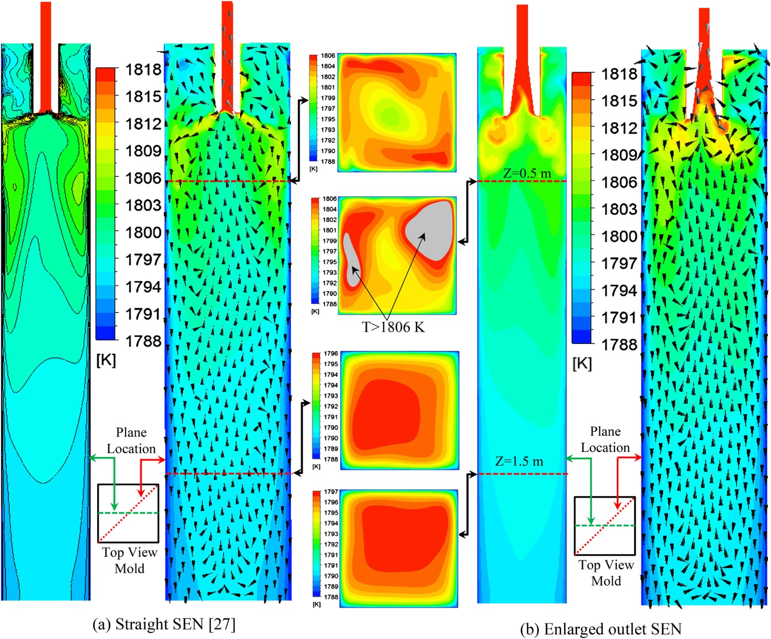
Intensive swirling flow with a high temperature could induce severe shear force and high heat flux to the mould wall, which might influence the formation and the thickness of the solidified shell. This influence was strongest on the top of the mould, since the steel flow had a strong horizontal velocity and a high temperature when it just moved out from a swirling flow SEN. Therefore, it was really needed to find out how these two SEN designs affected them on the top part of the mould. Figure 11 shows the wall shear stress distribution on the mould wall with different SEN designs. The swirling flow inside the straight SEN could give the liquid steel a strong impact on the solidification front and a larger wall shear stress region appeared on the mould wall due to the high-velocity gradient. The wall shear stress was smaller with the enlarged outlet SEN. Figure 12 shows the heat flux on the top of the mould. The high heat flux region was located at the region where the hot steel from SEN outlet comes in contact with the solidified shell. The straight SEN design induced a bit larger high-heat-flux region compared to the enlarged SEN design. The solidification behaviour in these high heat flux region was still required a further study in the future to avoid a too small thickness of the solidified shell. Wall shear stress distribution on the top of the mould. Wall heat flux distribution on the top of the mould.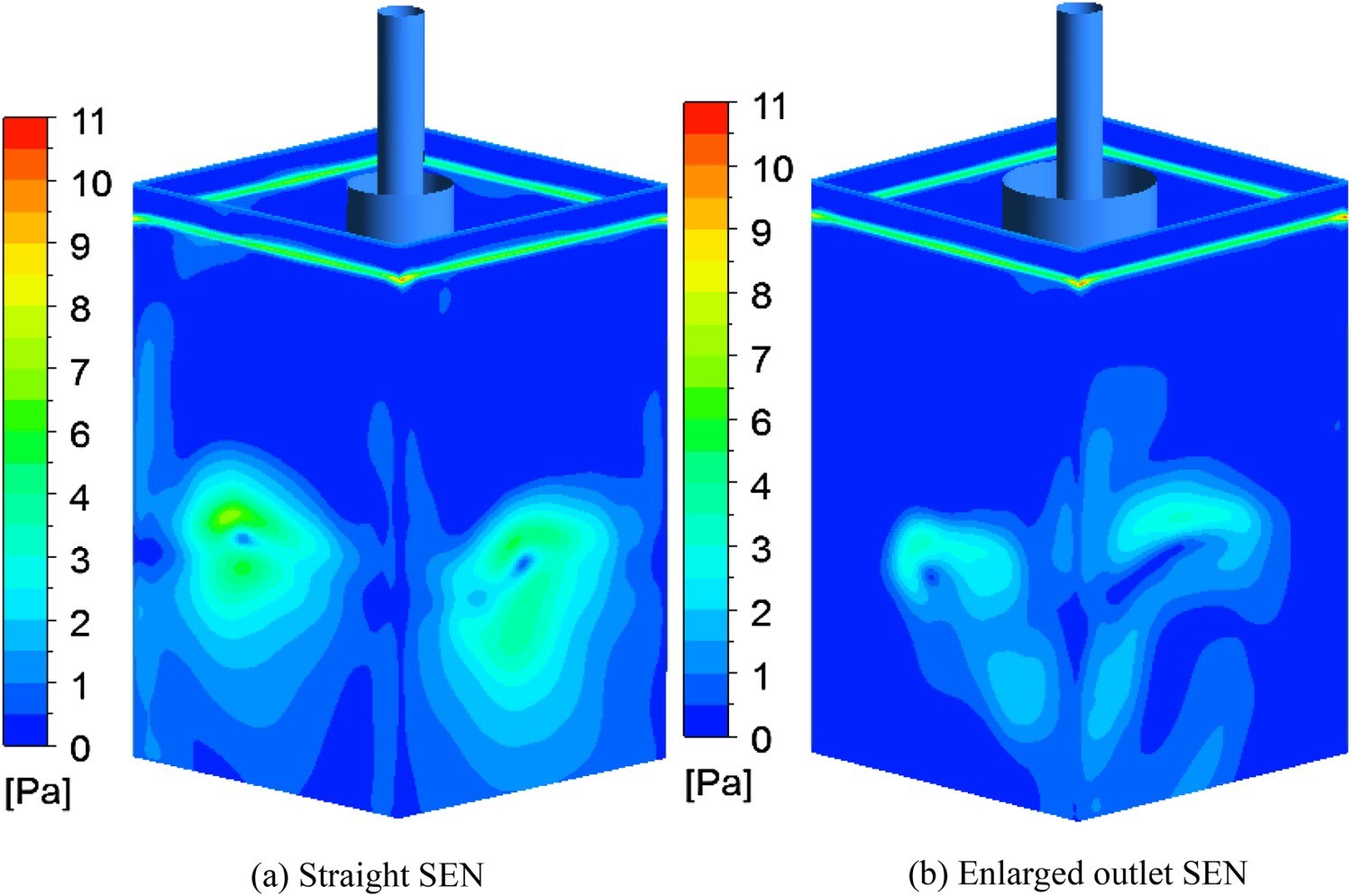
Conclusions
Effect of swirling flow from two designs of SEN outlet geometry on the multiphase flow and heat transfer in a mould were investigated by using numerical simulations. The main conclusions were as following: Liquid steel flow pattern and heat transfer in mould were significantly changed with swirling flow SEN. The influence of the SEN outlet design mainly existed on the top part of the mould. With an enlarged SEN outlet, the horizontal steel flow coming out from the SEN became slow. The flow velocity and turbulent kinetic energy near the meniscus were reduced. In the deep of the mould, the influence induced by the current SEN design was slight. On the steel/slag interface, the thickness of the steel/slag mixing layer decreased from 2.6 cm to 1.4 cm, and the calculated maximum Weber number decreased from 0.2–0.08. Therefore, a more stable steel/slag interface was obtained by using an enlarged outlet SEN. The temperature distribution had a similar distribution to the velocity distribution. With the enlarged outlet SEN design, a high-temperature region appeared near the SEN outlet. The superheat removal became a little slower, and the temperature near the meniscus increased.