
Abstract
Sulphur removal in the ironmaking and oxygen steelmaking process is reviewed. A sulphur balance is made for the steelmaking process of Tata Steel IJmuiden, the Netherlands. There are four stages where sulphur can be removed: in the blast furnace (BF), during hot metal (HM) pretreatment, in the converter and during the secondary metallurgy (SM) treatment. For sulphur removal a low oxygen activity and a basic slag are required. In the BF typically 90% of the sulphur is removed; still, the HM contains about 0.03% of sulphur. Different HM desulphurisation processes are used worldwide. With co-injection or the Kanbara reactor, sulphur concentrations below 0.001% are reached. Basic slag helps desulphurisation in the converter. However, sulphur increase is not uncommon in the converter due to high oxygen activity and sulphur input via scrap and additions. For low sulphur concentrations SM desulphurisation, with a decreased oxygen activity and a basic slag, is always required.
Activity (–)
Gibbs free energy (J mol−1)
Enthalpy (J mol−1)
Equilibrium constant (–)
Entropy (J mol−1 K−1)
Temperature (K)
Introduction
In today’s world manufacturers and end users demand steel of an ever-increasing quality. However, the overall quality of the raw materials (iron ore, coke and coal) is decreasing, because the raw material reserves are not endless and the best materials have mostly been used in the past. This means that the steel industry needs to cope with more impurities, but their final products should contain less impurities.
Today, roughly two-thirds of the world’s steel is produced via the integrated blast furnace-basic oxygen furnace (BF-BOF) route. In this process, iron ore is reduced mainly by coke in the blast furnace (BF). This coke also produces the required heat by reacting with the available oxygen (from the hot blast and the FeO). The liquid hot metal (HM) that leaves the BF contains impurities, which have to be removed later in the process. In the HM pretreatment, usually most of the sulphur (and sometimes silicon and phosphorus as well) is removed. The HM is then charged to the basic oxygen furnace or converter, together with scrap, where it is oxidised by blowing pure oxygen on the melt, and most of the carbon (remaining) silicon and phosphorus is removed. The produced liquid steel is tapped from the converter and sent to the secondary metallurgy (SM) ladle treatment before being cast. Here remaining impurities are removed, and alloying elements and deoxidisers are added. When the steel has the desired chemical composition, it is cast into solid steel. Figure 1 gives a schematic overview of the BF-BOF steelmaking process
1–5
. Block scheme of the BF-BOF steelmaking process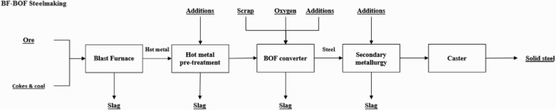
One of the above-mentioned unwanted impurities in the steelmaking process is sulphur (although there are certain steel grades that require sulphur). Sulphur increases the brittleness of steel and decreases the weldability and corrosion resistance 6,7 . Therefore sulphur needs to be removed, to typically below 0.015%. The main source of sulphur in the BF-BOF steelmaking process comes from coke. Even though roughly 40% of the sulphur in coal is removed in the coking process, typical sulphur levels in coke remain around 0.5%. Iron ore contains typically 0.01% sulphur and is only a minor source of sulphur in the steelmaking process 2,8 .
In the BF-BOF process there are four process steps where sulphur can be removed: BF; HM pretreatment; converter; SM ladle treatment.
The other main steelmaking process, the electric arc furnace (EAF) process (used for 30% of the world’s steel production), is not discussed in this paper. In the EAF, the scrap types used control the sulphur concentration of the liquid steel. The SM ladle treatment processes are comparable for both BF-BOF and EAF steelmaking. However, sulphur removal is less of an issue in the EAF process, since its raw materials (scrap, direct reduced iron) contain less sulphur than the raw materials of the BF-BOF process (iron ore, coke and coal) 1,4 .
Sulphur distribution flow
To get an overview of the sulphur input and output throughout the BF-BOF steelmaking process, a balance of the sulphur flows during the production of a standard steel grade (maximum allowed sulphur concentration of 0.01% at casting) at Tata Steel IJmuiden was made. Data of 2548 heats in total of this steel grade, produced in 2015, were analysed. For sulphur concentrations that are not measured for every single heat and that could not be derived from other measurements of these heats, random samples that were taken in 2015 or best guesses were used. For the BF data of one month in 2015 were selected. This month had the highest sulphur input of 2015. The HM output of the BF and the input of the hot metal desulphurisation (HMD) were averaged to determine the single stream in this diagram. The average sulphur presence in every process flow (in kg of sulphur per tonne of produced steel) is given in Table 1. A Sankey-type diagram of the sulphur balance of the production of this steel grade is given in Fig. 2. The balance between sulphur input and output for the BF and the BOF is simply added as an extra flow. This is done because the accuracy of the measured sulphur concentration or the mass flow is not the same for every flow. For example, the sulphur concentration in the HM that leaves the BF is measured more accurately than the sulphur concentration in the slag. For the HMD and the SM, it is assumed that all sulphur that is measured at the station’s input and that is not at the station’s output in off-gas or liquid metal is in the slag. Sankey-type diagram of the sulphur distribution flow for a standard steel grade at Tata Steel IJmuiden in 2015. Arrows represent the amount of sulphur present in a flow, necessary for one tonne of produced steel. Below the process blocks the percentage of sulphur input that is removed in that process step is indicated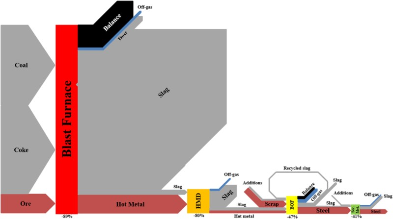
Average values of sulphur streams (in kg of sulphur per tonne of produced steel) for a standard steel grade at Tata Steel IJmuiden in 2015
The balance shows the enormous desulphurisation capacity of the BF. Around 90% of the sulphur input is already removed in the BF. It also shows the great importance of the HMD step. When looking at the poor desulphurisation capacity of the converter (for this steel grade the sulphur concentration of the liquid metal even increases), sulphur removal has to take place at the HMD to avoid a too heavy desulphurisation demand from the SM. When more sulphur needs to be removed during SM, that process will take more time. This could lead to a bottleneck in the entire BF-BOF process. Furthermore, sulphur removal before the BOF process has lower costs than afterwards.
At the BF more than 40% of the sulphur input comes from coal. This is because at Tata Steel almost half of the carbon input in the BF originates from coal by pulverised coal injection (PCI). In most BFs the coal input is much lower. Since coal contains more sulphur than coke, the total sulphur input to the BF will increase.
After the HMD, more sulphur is added to the converter via the HMD slag than via the HM itself. The total sulphur stream via the slag is less accurate, since it is calculated and not directly measured. However, it does emphasise the importance of good deslagging.
Thermodynamics
Introduction
Independent of where sulphur removal takes place, it is based on the same chemical equations. The circumstances of the individual processes only have an impact on the importance of the chemical equations. The removal of sulphur is based on one principle: to move the dissolved sulphur from the iron to the slag, after which the slag layer is separated from the metal. This leads to the following reaction, for the sulphur transfer between the metal and slag
2,9
:
Lime

Overview of ΔG 0 and log(K) equations for the reaction between CaO and [S] (reaction 3)
aThe temperature-independent term in Kitamura’s log(K) equation was written as 1528, but this was considered as a typing error.
The difference between Turkdogan and Hayes is that Turkdogan assumes a lower standard Gibbs free energy of formation of CaO 9,12 .
To get a clear overview of the differences between the mentioned sources, the ΔG0 equations are plotted in Fig. 3 for the temperature range of 1250–1450°C. Temperature dependence of ΔG
0 for the reaction between CaO and [S] (reaction 3), according to the literature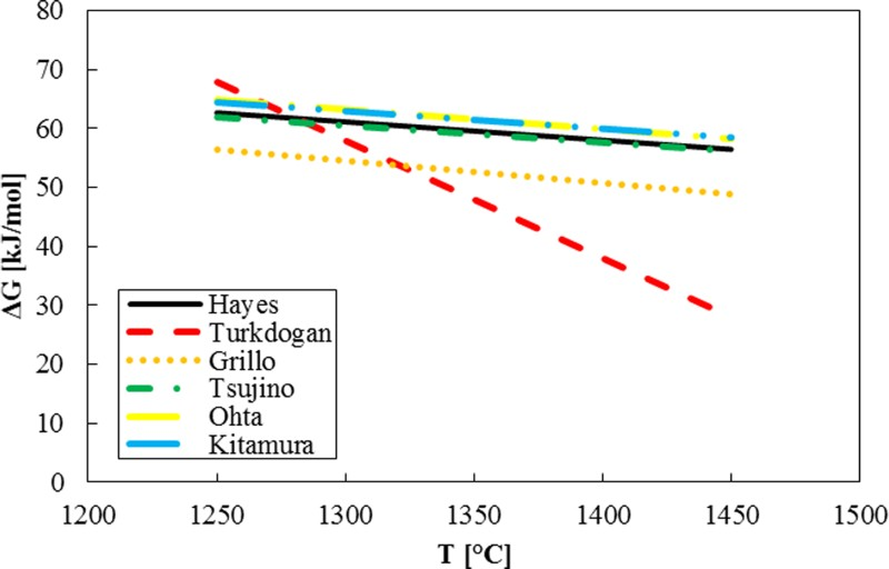
Both the Gibbs free energy equation and the chemical equilibrium equation show that the reaction between CaO and [S] is favoured at higher temperatures. This is in accordance with plant experience.
Calcium carbide
For the reaction of sulphur with calcium carbide (reaction (4)) it is assumed that the formed carbon does not dissolve in already carbon-saturated HM
16
. When CaC2 is used in steel desulphurisation, where there is no carbon saturation, the dissolution of carbon in iron should be taken into account.
Both equations indicate that thermodynamically the reaction is favoured at lower temperatures. This, however, is contradictory to industrial experience, where CaC2 desulphurisation efficiency increases at higher temperatures. As with the reaction with lime (reaction (3)), this reaction is controlled by kinetics rather than thermodynamics. Furthermore, it should be noted that CaC2 in industrial practice is only 50–70% pure (the rest is mainly lime (20–30%) and carbon). These impurities have their influence on the process and could partly explain a gap between theoretical behaviour and plant experience 16,18 .
Magnesium
Magnesium is only used for HMD and not for post-converter desulphurisation. It has a boiling point of 1105°C, and hence in contact with HM (1250–1450°C) it will vaporise. Magnesium gas dissolves into liquid iron, after which it can react with the dissolved sulphur (reaction (7)). The magnesium gas can also react directly with the dissolved sulphur at the bubble/metal interface, but this has only a small contribution as will be further discussed in the section ‘Kinetics’.
From plant experience it is known that this reaction proceeds better at lower temperatures. Figure 4 gives the amount of industrial magnesium (purity unknown, but typically between 80 and 95% Mg) required to remove 1 kg of S in the HM set against the HM temperature in a Mg–CaO co-injection HMD station in a South American plant for 2158 heats in 2006. The average heat size was 92 t and the average reagent injection ratio of CaO:Mg was 4:1. The stochiometric consumption of Mg to form MgS equals 0.76 kg Mg per 1 kg S. Amount of Mg used to remove 1 kg of sulphur at different HM temperatures. Data of 2158 heats at the HMD in a South American plant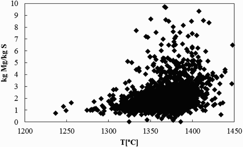
The plant data clearly show that, at lower HM temperatures, less magnesium is required to remove 1 kg of dissolved sulphur. The thermodynamics support the observation that lower temperatures have a positive effect on the desulphurisation efficiency of magnesium.
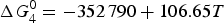
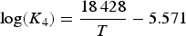
Overview of ΔG 0 and log(K) equations for the reaction between [Mg] and [S] (reaction 7)
The equations for ΔG
0 of Table 3 are plotted in Fig. 5 to show the scatter from the different sources. Temperature dependence of ΔG
0 for the reaction between [Mg] and [S] (reaction 7), according to the literature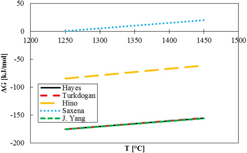
Resulphurisation
A disadvantage of desulphurisation with magnesium is the so-called resulphurisation, the net sulphur transfer from the slag back to the metal. The MgS in the slag reacts with oxygen from the air, or from other sources, forming MgO and unbounded sulphur (reaction (8))
20
:

The equation for its Gibbs free energy is
12
Kinetics
Desulphurisation by CaO or CaC2 is in reality controlled by kinetics rather than thermodynamics
2,18,21
. When CaO reacts with sulphur, CaS is formed (reaction (3)). This CaS forms a layer around the CaO particle, through which other dissolved S atoms need to permeate before they can react with CaO. Since also oxygen is formed in this reaction, the oxygen activity increases around the CaO particle. This oxygen reacts with either carbon (forming CO) or silicon, which leads to the formation of 2CaO–SiO2 (reaction (11)). This 2CaO–SiO2 contributes to the non-reactive shell around the CaO, decreasing its desulphurisation efficiency. However, with small CaO particles (<50 μm) not enough oxygen is created via reaction (3) to initiate the following reaction
21
:
The kinetics of magnesium desulphurisation causes some discussion among the experts in the field. Irons and Guthrie 22 claim that 90% of the magnesium first dissolves before it reacts with [S] and less than 10% of the Mg-desulphurisation is heterogeneous (Mg gas at the bubble/metal interface). The formed MgS precipitates on CaO particles. Yang et al. 20 and Lindström 21 conclude from their experiments (on lab scale) that more than 90% of the Mg desulphurisation is heterogeneous and that only a little Mg first dissolves before it reacts. Visser 7 discussed both views and concluded, also based on plant data, that the kinetic model of Irons and Guthrie 22 predicts the reality on plant scale best and therefore that the route via dissolved Mg is dominant.
Sulphur removal in the BF
In the BF typically 2.5–3.5 kg/tHM of sulphur is introduced through the raw material input. Typically 80–90% of the sulphur enters the process via coke. However, in steel plants that add a large amount of coal (PCI) or fuel oil, up to 45% of the sulphur can be added via these fuels. Ore typically contributes to around 10% of the sulphur input. Usually roughly 90% of the sulphur is also removed during the BF process. This happens mostly via the slag and about 2–3% via dust and off-gas such as SO2 and H2S. Only 10–11% of the initial sulphur in the charged material ends up in the HM 1,11 .
In the BF, part of the sulphur (from sulphides and sulphates) dissolves in the HM. The largest part of the dissolved sulphur is removed by the lime present in the slag via reaction (3). The calcination of limestone (reaction (12)) is highly endothermic. This means that when more limestone is charged to the BF, in order to increase the basicity, also more coke should be added in order to compensate for the energy/temperature loss. A rule of thumb is that, in the BF, 100 kg of extra limestone needs to be compensated by 25–35 kg coke. With the extra coke, also extra sulphur is added to the BF. These additions require more volume as well, decreasing the iron output. Therefore it is more efficient to remove the last 10% sulphur later in the steelmaking process
1,11
.
An alternative for desulphurisation with lime is the use of magnesium oxide. MgO in the slag and dissolved sulphur react via the following reaction (based on reaction (1)). MgO, however, is a less effective desulphuriser than CaO, since the affinity of Mg to sulphur is less than the affinity of Ca to sulphur. In typical BF slag there is 10% MgO and 40% CaO
1,11
.
Since the main desulphurisation reaction with lime (reaction (3)) is endothermic, better desulphurisation in the BF can be achieved by higher temperatures. Also a longer contact time between the slag and the metal is beneficial for sulphur removal. This can be achieved by tapping the BF more often or by increasing the slag volume. Furthermore, several compounds have their influence on the desulphurisation process. For better desulphurisation
1,11,23
the following conditions should be fulfilled: Oxygen activity in the HM (a[O]) should be as low as possible (Equation 2). Carbon should be high (it reacts with oxygen and thus reduces a[O]). Silicon should be high (it reacts with oxygen as well and thus reduces a[O]). Manganese should be high (it reacts with sulphur to form MnS).
Although the BF is an efficient desulphuriser, a significant amount of sulphur will remain in the HM. Therefore sulphur removal further down the line in the steelmaking process remains inevitable.
Hot metal desulphurisation
HM that leaves the BF typically contains 0.03% sulphur, but the demand for the steel can be as low as 0.001% sulphur (e.g. HIC steel) 24–26 . Therefore most steel plants worldwide have HMD, because it is more process- and cost-efficient to desulphurise before the converter 2 .
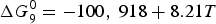
Torpedo desulphurisation
Initially (in the 1960s and 1970s) HMD took place in the torpedo cars that transported the HM from the BF to the steel plant (see Fig. 6). Typical reagents were calcium carbide (reaction (4)), soda ash and blends of magnesium and lime. During torpedo desulphurisation the reagent is injected into the HM via a lance; nitrogen is used as a carrier gas. The reagent reacts with the sulphur in the HM and the sulphides CaS or Na2S ascend to the slag layer. This slag is then raked off with a skimmer
16,27
. Schematic overview of torpedo desulphurisation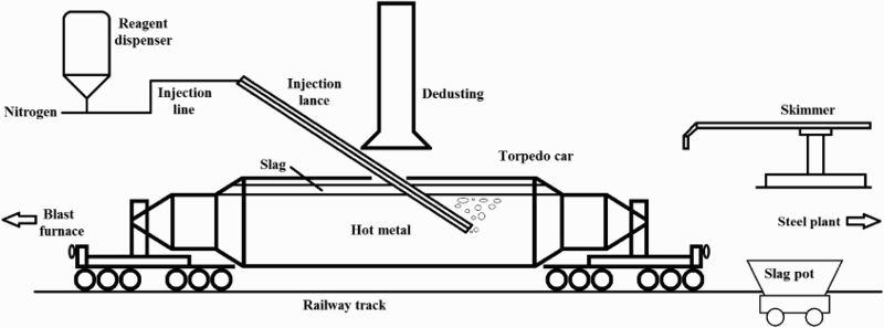
The shape of the torpedo is designed for temperature preservation and not as a metallurgical reactor vessel. The HM bath is not very deep (1–2 m), so the reagent particles (which have a lower density than the HM) quickly rise to the top. Therefore, the reagents only have a short contact time with the HM. Reagent mixing is poor, which means that both far ends of the torpedo are not reached by the reagents. Finally a torpedo has only a small opening at the top, which makes it difficult to rake off the slag. This leads to resulphurisation via the remaining slag and high iron losses. Because of these drawbacks, torpedo desulphurisation was replaced by ladle desulphurisation in most steel plants 16 . Still with torpedo desulphurisation final sulphur concentrations at converter charge (including resulphurisation) as low as 0.002% are reported in the literature 28,29 .
Co-injection
Co-injection is an HMD process in which both magnesium and fluidised lime or calcium carbide are injected into the HM (multi-injection, which uses all three reagents, is a variation of this process). Co-injection is used worldwide and is, certainly in Europe and North America, considered as the industrial standard. Via a submerged refractory coated lance the reagents are injected at the bottom of the HM ladle. An inert carrier gas (usually nitrogen) transports the reagents through the injection line and creates enough turbulence in the ladle for proper mixing. The mixing of the reagents takes place in the injection line, which makes it possible to change the ratio of the reagents during the process. When the reagents react with sulphur, the products (MgS and CaS) ascend to the slag layer, where it is removed with a skimmer. Fig. 7 gives a schematic overview of the co-injection process. Schematic overview of co-injection desulphurisation
Co-injection combines the advantages of magnesium (faster process) and lime/calcium carbide (deep desulphurisation). Most sulphur will initially react with magnesium to form MgS. The lime will mostly prevent the resulphurisation via reaction (9).
With magnesium/lime co-injection, sulphur concentrations below 0.001% (10 ppm) have been reported in the literature 29–32 . At the plants of Tata Steel IJmuiden and Port Talbot a significant amount of heats had a measured final sulphur concentrations below 0.001% with co-injection.
Kanbara reactor
The Kanbara reactor (KR) is an HMD process developed in 1965 in Hirohata (Japan) by Nippon Steel. The KR uses relatively cheap coarse lime (often with an additional 5–10% CaF2; calcium carbide is an alternative) as the reagent, which is usually added on top of the HM ladle during the first few minutes of the process. Typically 5–15 kg/tHM of reagent is added. An immersed impellor (at one-third of the bath depth) is used to mix the reagent with the HM. The mixing is required because the reaction between lime and sulphur (reaction (3)) is relatively slow, so that the contact time needs to be increased. The impellor has a typical rotational speed of 60–120 rev min−1 and an average life of about 200 heats. The stirring takes 5–15 min after which the impellor is lifted again and the bath is allowed to rest for another 5–10 min. This is necessary because the slag and the formed CaS need time to ascend to the top. After this the slag layer is skimmed off, which takes 10–15 min
2,16,28,31
(Fig. 8). Schematic overview of a KR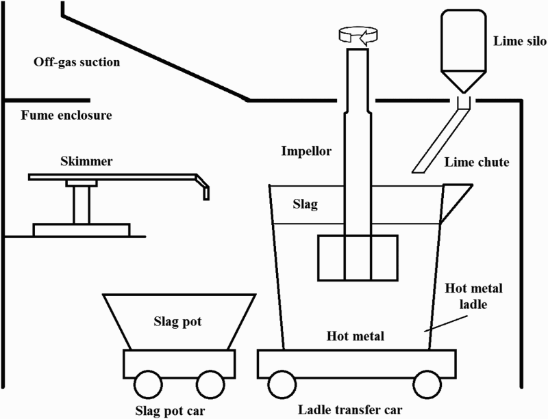
Around 1970 a similar process, called Rheinstahl-Rührer, was developed in Germany. It was soon abandoned due to the large slag volumes created 16 . The KR is widely applied in Asia (especially Japan). With the KR, sulphur concentrations below 0.001% (10 ppm) have been reported in the literature 28,31 .
Magnesium mono-injection
Magnesium mono-injection (MMI), also referred to as the Ukraina-Desmag process
33
, is an HMD process that uses only magnesium as a reagent. The process was developed between 1969 and 1972 by the Ukrainian Academy of Sciences. In MMI the magnesium is injected into the HM under pressure via a submerged refractory coated lance. Nitrogen is most often used as a carrier gas. Usually a lance with an evaporation chamber at the end (Fig. 9) is used, but also straight lances can be used. Turbulence is created by evaporation of the magnesium powder. At higher injection rates the turbulence can become a problem, increasing the iron loss by splashing. Therefore the evaporation chamber at the end of the lance is used to allow the magnesium to evaporate earlier, thus reducing the turbulence
33,34
. Schematic overview of MMI desulphurisation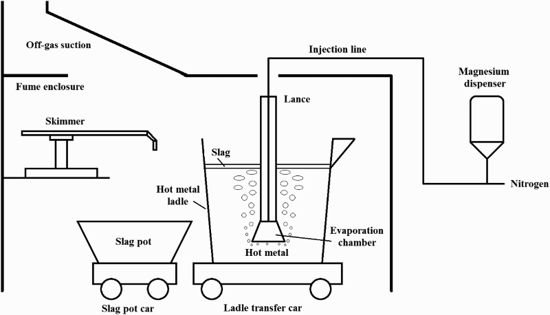
Because magnesium reacts with sulphur (reaction (7)) much faster than lime (reaction (3)) and calcium carbide (reaction (4)) 35 , MMI is a very fast desulphurisation process, in which very little slag is created. A major disadvantage of MMI is the severe resulphurisation (reaction (12)). When no lime is used to prevent this, the sulphur concentration of the HM will increase significantly before converter charging. Resulphurisation can sometimes undo the desulphurisation process almost completely 20,36 .
Sulphur removal in the converter
The main targets of a BOF converter are decarburisation, dephosphorisation and increasing the temperature of HM and scrap in order to make steel with a specified composition. Sulphur removal is at best a minor target. To remove carbon and phosphorus, and to increase the temperature, oxygen is blown into the HM (which leads to an exothermic reaction with the dissolved carbon to form CO). The resulting increase in oxygen activity in the melt has a negative effect on the desulphurisation. At the slag/metal interface, the reverse of reaction (1) takes place (effectively transferring sulphur from the slag back to the metal). On the other hand, part of the sulphur (15–25%) is directly oxidised via reaction (14) and leaves the process
3,10
.
Dephosphorisation is favoured by a high basicity, a low slag temperature and a high FeO content in the slag (thus a high oxygen activity). To achieve better dephosphorisation, the converter slag’s basicity is increased by adding lime to the process (leading to a typical basicity of 2–4). This lime has a positive effect on the desulphurisation (reaction (3)). In most converters 30–45% of the sulphur ends up via this reaction as CaS in the slag 10,37 .
During the converter process, sulphur is added to the system through scrap and additions. Between 10 and 30% of the iron input in the converter comes from scrap, which contains typically 0.015–0.04% sulphur 38 . From the additions most sulphur input is contributed via ore that is used to cool the steel. Ore contains 0.015–0.025% of sulphur.
Overall some desulphurisation takes place during the converter process. On the other hand, sulphur is added via scrap and additions. This means that it differs from plant to plant (or even between steel grades) if the sulphur concentration in the metal increases or decreases during the BOF process. Minimum sulphur levels at tapping are reported to be in the range of 0.003–0.004% 29 .
Steel desulphurisation
SM is the last possibility to influence the steel’s chemistry. For low sulphur steel grades (<0.002% 9 ) steel desulphurisation is inevitable. Liquid steel at the end of the BOF process has a high oxygen content (typically 200–800 ppm 4 ), which is unwanted for the following process steps. Therefore most steel plants deoxidise the steel by adding Si, Mn and Al. The oxides end up in the slag. This slag needs to be basic for desulphurisation, therefore calcium-based reagents (usually lime) are added 4,9,39,40 .
Lower oxygen activities in the steel enhance steel desulphurisation. After deoxidation (with Al) the oxygen activity is around 2–4 ppm, which is comparable to that of HM. The steel temperature (∼1600°C) is higher than that of HM (∼1300°C). This means that magnesium is no longer an option as a reagent due to its high vapour pressure. With aluminium and lime, desulphurisation takes place via reaction (15) (which is a variation on reaction (3), but where oxygen is now bound to aluminium)
9,10,39–41
:
Overview of SM processes and their ability to desulphurise steel
Vacuum-based processes
In a vacuum degasser (VD) or tank degasser either the ladle or a vessel that contains the ladle is put under vacuum. Argon is bubbled in the ladle via the bottom and additions are thrown from the top or inserted via wire (also possible during the process). Optionally an oxygen lance is installed for further reducing (making it a vacuum oxygen decarburisation station, or VOD) 5,9,40 .
Typically 0.2–0.5 L(stp) per tonne of steel per minute Ar is blown in and 3–5 kg t−1 lime-based reagent is added. (Most additions, 5–15 kg t−1, are already made during converter tapping.) Pressure can be reduced to 1 mbar. The total process takes typically 25 min. During the VD process a lot of turbulence is generated. This creates ideal kinetic circumstances with excellent slag–metal mixing, which can lead to final sulphur levels of <0.001% (10 ppm) 5,9,10,14,29 .
The recirculation degasser or RH is in its standard version not well suited for desulphurisation because there is not enough interaction between the steel and the desulphurising slag. When a top oxygen lance (connected to a dispenser) is added (RH-KTB), a lime-based reagent is inserted into the vacuum vessel, allowing desulphurisation even to <0.001%. This is still less efficient than VD, since more reagent is required 5,40,42 .
Ladle furnace
In the ladle furnace (LF) the steel is reheated by inserting three electrodes that create an electric arc inside the steel. Materials (for desulphurisation aluminium and lime, sometimes in combination with CaF2 or Si) are added by throwing it on top of the steel, injecting it via a lance or by wire feeding. Argon is injected through the bottom for steel bath homogenisation 5,9 .
For desulphurisation up to 7 L(stp) per tonne of steel per minute Ar is blown in (most via the injection lance) and 5–15 kg t−1 of materials are added. The total process takes typically 45 min. The main limitation for desulphurisation in the LF is the high oxygen activity in the steel, making desulphurisation below 0.005% S without vacuum treatment or aluminium addition difficult. For Al-deoxidised steel grades it is possible to desulphurise to <0.002%. This is impossible for Si-deoxidised steel grades, because of the low slag basicity and the higher oxygen content of the steel of 20 ppm) 5,9,39,40,43 .
Other SM processes
Stirring station: Argon is injected in the ladle via bottom plugs and calcium (CaO, CaSi or CaFe) is injected via a lance or added by wire feeding. By adding calcium, the stirring station is suited for desulphurisation
5,40
.
Powder injection: This process is similar to HMD injection processes. CaO, CaC2 and CaSi (sometimes in combination with Al) are used as reagents. Sulphur concentrations below 0.002% can be reached for Al-killed steel
5,40
.
Wire feeder: This process is comparable with powder injection. The difference is that the reagents are contained in a hollow wire that is shot into the steel at a speed of 1–4 m s−1 (allowing the wire to penetrate the bath 1.5–2 m before the coating is completely melted and the reagents are freed). Wire feeders are typically suited for lime additions below 0.2 kg t−1. Sulphur concentrations below 0.002% can be reached (when the steel is Al-deoxidised)
5,40
.
Chemical heating station or CAS-OB: Its main purpose is to reheat the steel (allowing a 15°C lower tapping temperature at the converter). CAS-OB creates little turbulence due to its bell, which leads to poor kinetics for desulphurisation with lime. Also oxygen is blown in, which further decreases the desulphurisation efficiency due to high oxygen activity. It is possible to add an injection lance (or wire feeder) to the CAS-OB, to inject desulphurisation reagents (lime, aluminium)
5,40
.
Outlook
In the twenty-first century the iron- and steelmaking industry will face new challenges. The quality of the raw materials will continue to decrease, since the high-quality stocks are depleting. This means that the sulphur amount added to the process will increase. On the other hand, the quality demands will continue to increase, implying that the sulphur content of the products will have to decrease. This will lead to an increased necessity for more efficient sulphur removal during ironmaking and steelmaking.
Undoubtedly one of the largest challenges for the steel industry will be reducing energy consumption and greenhouse gas emissions. The European steel industry and the European Union have committed themselves to reducing CO2 emissions of the steel industry by 50% by 2050. Most likely the biggest changes will involve the ironmaking process (coke making, ore agglomeration and BF), since it is the largest producer of CO and CO2 44–46 .
Already in the 1970s and 1980s the COREX process was developed. In this process coal (to replace the majority of coke) is used to create CO and H2 to reduce the iron ore and melt the iron. By its more efficient energy utilisation, less CO2 per tonne of HM is produced. Worldwide a few commercial COREX plants were built, but their HM production (0.3–2.0 Mt/y) remains low compared to the average production of one BF. The BF process remains more cost-effective in producing larger amounts of HM 1,47 .
One recent development is the HIsarna process, a collaboration between various European steelmaking companies and universities and Rio Tinto from Australia. It is one of the outcomes of the European Union ULCOS project in combination with the HIsmelt technology. The pilot plant is operated at the site of Tata Steel IJmuiden. HIsarna uses coal and untreated fine iron ore as raw materials instead of coke and agglomerated iron ore. By skipping the pretreatment of raw materials, the overall energy consumption is decreased and the net CO2 emissions are decreased by 20% 44–46 .
However, by using coal instead of coke, the sulphur concentration in the HM increases. At the same time, HM produced in HIsarna contains almost no silicon, which reduces desulphurisation efficiency. This means HMD needs to be intensified, since the sulphur aims remain the same or will even be lower in the future. Therefore part of further development will be devoted to sulphur control 46 .
Another possibility is to reduce the iron (partly) by something other than coal/coke. Natural gas, biomass or hydrogen gas are mentioned as alternatives 45 . This would lead to HM with a low sulphur range. For the heats that still require desulphurisation, magnesium-based HMD methods would become less attractive.
With the ever-increasing customer demand for low-sulphur steel on one hand and the environmental challenges of the steel industry on the other hand, sulphur removal will remain a key issue for steelmakers. In this changing environment sulphur removal methods should continue to be developed and adapted. This will also create the necessity for a new optimisation between the different sulphur removal steps within the ironmaking and steelmaking process.
Concluding remarks
Sulphur removal in steelmaking becomes less efficient when it is done further down the process chain. It is therefore important, from a process and economical point of view, to remove most of the sulphur from iron before it enters the oxygen steelmaking converter. Since it is not efficient to desulphurise HM below 0.03% of sulphur in the BF, HMD will be an essential part of the production of lower sulphur steel grades. However, due to additional sulphur input in the converter, desulphurisation in SM remains inevitable for these steel grades. A steel plant ready for twenty-first century customer demands needs to be able to desulphurise by means of HM pretreatment as well as by SM, and needs to be able to control the sulphur levels in the BF and the oxygen steelmaking converter.
Footnotes
Acknowledgements
The authors wish to thank Tata Steel Europe for providing process data for this paper and for supporting this study together with Danieli Corus.
Disclosure statement
No potential conflict of interest was reported by the authors.