
Abstract
Motors are essential components in electric vehicles and there are at present worldwide efforts to improve their efficiency and reduce their weight. One of these areas concerns improving the quality of steel laminations that are used for their magnetic properties in rotors and stators. These are ‘soft’ magnetically, meaning that they can be easily magnetised and demagnetised. Improvements in magnetic quality, i.e. reductions in power loss during magnetisation, have been pursued for many years but the high-speed motors in vehicles are also subject to greater mechanical loading, in particular in the rotors of IPM-machines (Internal Permanent Magnet rotor machines). These are the dominating type of electric motor for electrified vehicles due to their high efficiency and high power/torque density. As a result, there are increasing requirements for new steel products that combine low power losses with high strength. This is difficult because most ways of raising the strength result in the magnetic characteristics becoming also undesirably harder. The present paper starts with a consideration of how magnetic power losses are defined and the factors that influence these. Then, different strengthening methods are considered together with their effects on magnetisation. Strengthening can be achieved by (i) solid solution alloying, (ii) grain refinement, (iii) work hardening, (iv) precipitation and (v) texture control. Most commonly, the requirements are in conflict. Only solid solution strengthening can confer benefits to both strength and power loss although extremely fine nanoprecipitation can raise the strength with little or no magnetic detriment. Based on this analysis, results from research publications and patents are summarised and reviewed.
Keywords
Background
Motor requirements
The IPM synchronous motor (Internal Permanent Magnet) is the most common type of electric motor for electric vehicles due to its high efficiency and torque/power density. In these motors, the magnetic flux between the rotor and stator is provided by permanent magnets inserted into slots of the rotor. Often the magnets are arranged in V-shaped pairs, forming one magnetic pole of the rotor (see Figure 1). The magnetic flux of the rotor is essentially constant during motor operation and the magnetic losses in the rotor are therefore small. The torque of the motor is proportional to the magnetic flux between the rotor and the stator and in order to maximise this flux, the ‘bridges’ of steel in the rotor, holding the permanent magnets in place, should be as small as possible to minimise the flux going between one pole of a magnet to the other pole of the same magnet through the rotor only i.e. without contributing to the torque of the motor. At the same time, the rotational speed is high to provide a motor with high power density. Maximal rotational speeds up to 15,000 rev min−1 are not uncommon which means that the small ‘bridges’ of steel, holding the permanent magnets in place, become highly stressed due to centrifugal forces. The high rotational speed is driven by a high frequency of the changes of the magnetic flux in the stator and the frequency is often further increased by a high number of poles in the rotor needed to maximise the torque and power density of the motor. Typical magnetisation cycle frequencies lie in the range 400–1000 Hz. The requirements on the properties of the steel in the rotor and stator are rather different, but due to cost reasons (stamping capacity, scrap rate, etc.) the same electrical steel strip is used for stamping of both the stator and the rotor laminations. Accordingly, there exists a need for materials that are easy to magnetise and demagnetise with a minimum of energy loss, particularly at high frequencies, but which also are mechanically strong. It is these we shall consider here. Frequently, though not always, the magnetic and mechanical demands are in conflict. It is not coincidental that materials which are easily magnetised are called ‘soft’ magnets. They often are!
Example of a rotor lamination for an electric motor stamped from sheet steel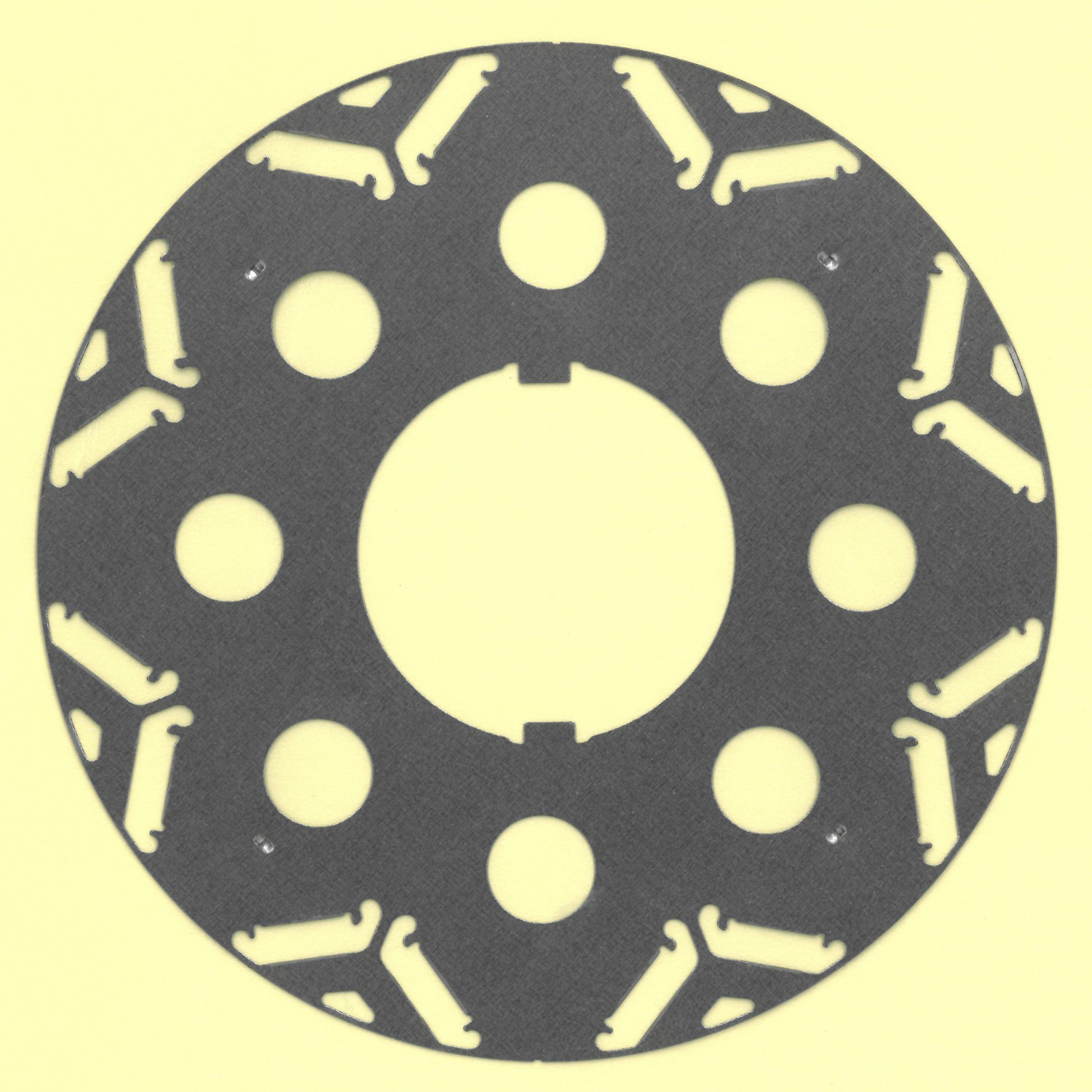
Magnetic behaviour
The rapid expansion of electrically powered vehicles is driving materials development that can provide improved performance and lower energy consumption in ways that are also cost-effective. A particular example concerns the magnetic materials (often denoted as electrical steels) that are used in the rotors and stators of the electric motors. The cyclic magnetisation of these components provides the conversion from electrical energy to kinetic energy for power but this process is not 100% efficient. Electrical resistance of the windings as well as friction consume power but so does the repeated magnetisation of components in the motor.
It needs to be pointed out that electrical steels exist in two quite different categories. Both grain-oriented (GO) and non-grain-oriented (NGO) steels are similarly alloyed with Si but have different applications. GO steels have intensely sharp preferred orientation or Goss texture which optimises the magnetic properties in one direction only. These are used in the cores of power transformers. NGO steels do, in fact, possess textures which although less intense are not insignificant. However, since these are used in rotating machines like motors, they benefit from textures which favour magnetisation in all directions in the sheet. It is these NGO steels that we consider in the present review.
Some recommended reference sources that are concerned with principles of magnetism and magnetic materials are Cullity et al. [1], Coey [2], Bertotti [3] and the old but still invaluable Bozorth [4]. Readers wanting more detailed explanation of magnetic phenomena are referred to these sources.
Power losses during magnetisation are usually quantified in units of Watts/kilogram under defined conditions of frequency (Hz) and maximum induction level Bmax (in Teslas, T). One conventional standard that has long been used is P15/50 which means the power loss at 50 Hz with a peak induction level of 1.5 T. However, motors for high-speed applications, e.g. for automotive applications, run at significantly higher frequencies and another alternative condition is, for example, P10/400. The interplay between a material in terms of its microstructure and its magnetic quality is complex, such that the actual optimum conditions in a motor vary not only with frequency and induction but also with sheet thickness as the components are typically made from stacks of sheared blanks, often with complicated shapes (e.g. Figure 1).
Magnetic power losses have three origins which contribute in different degrees depending on the circumstance; these are hysteresis loss, eddy current loss and anomalous or excess loss.
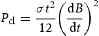
Hysteresis losses arise from the area inside a B–H loop during nearly static magnetisation conditions and are then proportional to the frequency. Inside the metal the local induction is not perfectly in phase with the field H (amps/metre) and this Barkhausen effect absorbs energy. The domain walls get hindered by microstructural defects such as dislocations, grain boundaries, particles, etc. A perfect, uniform structure is, therefore, the best for minimising hysteresis losses Eddy current losses arise because the magnetisation varies with time. The energy is irreversibly transformed into heat through Joule dissipation. When magnetising a slab in ac conditions with a low frequency, the classical power loss due to the eddy currents is:
Which for sinusoidal induction gives:
At higher frequencies, the induction will vary through the thickness of the slab and the calculation of the eddy currents will be more complex.
The sum of hysteresis and eddy current losses is usually less than the measured total loss. The difference was earlier called the anomalous loss but the name excess loss is becoming more common. The origin of this has been identified as local eddy currents that flow around domain walls as these move through the crystal to achieve the change in magnetisation. These are also reduced by alloying, for example with silicon, that increases the resistivity. These local power losses vary with the speed of movement of the domain walls and thus with the frequency of magnetisation. According to various sources, anomalous power losses depend on frequency as f2, e.g. [5] or as f3/2 [3]. They also vary with the spacing between domain walls as the distance moved is typically half this spacing. Domains cannot be bigger than the crystals in which they exist and usually there are many domains within each crystal although the domains are bigger in larger grains. This means that the anomalous loss tends to increase with increase in grain size since the wall velocity must become greater to achieve the same rate of change in magnetisation.
An additional parameter of importance in magnetisation is the crystalline anisotropy coefficient (K1) which describes the magnetic energy as a function of the magnetisation vector direction in the crystal. In iron alloys K1 is positive and the ‘easy’ direction of magnetisation is 〈100〉 . In the absence of an external field all domains are spontaneously magnetised along these directions. This parameter is significant because the specific energy of domain walls varies as 1/√K1 and this energy term affects the ease of motion of the walls. Alloying has an influence on K1 so can influence the power loss in this way. For example, alloying with silicon lowers K1 which reduces the domain wall energy and confers an extra benefit in addition to that from the higher resistivity.
Mechanical strength
There are several different ways in which steel chemistry and microstructure can be adapted to raise the strength of steels. Further information on this subject is available in numerous texts on physical/mechanical metallurgy such as Hosford [6], Dieter [7] and Hull and Bacon [8] to which readers are referred for more details. These strengthening mechanisms are:
Solid solution hardening due to foreign atoms substituted on the iron atom sites or in interstitial positions in the lattice Grain size reduction Precipitation of second phase particles Work hardening by plastic deformation Texture or orientation anisotropy
We will consider these individually and also in relation to their effects on magnetism and power loss of the steels.
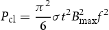
Theoretical treatments of solid solution hardening do exist but for practical purposes the change in strength in dilute alloys of iron (<∼3% alloy element) can be considered as a linear function of the composition and is almost always an increase. At the same time, the electrical resistivity also rises which is beneficial for reducing eddy current losses, especially at higher frequencies. Foreign atoms that differ is size greatly from iron atoms are expected to raise both strength and resistivity so are ideal provided that other limitations such as workability do not impinge. Figure 2 shows a plot of how additions of 1% of different elements in solid solution in iron affect the yield stress and the resistivity. Most of these values are taken from [4
9] with some additional values from [10,11] and may differ marginally from other literature values but the trend of a positive correlation is evident. Silicon, in particular, is very beneficial both for reducing eddy current and anomalous losses as well as for raising the strength. Phosphorus has a very powerful hardening effect but its solubility is more limited and it has an unfortunate tendency to cause brittleness. Similarly, carbon and nitrogen in solution raise the yield stress vastly, by the equivalent of ∼3700 MPa per 1%, but their maximum solubility is only about 0.02% and they also result in aging effects that greatly degrade the soft magnetic quality, so are specifically avoided. All these elements reduce the saturation magnetisation Js which is a disadvantage as the amount of core metal must be increased in compensation. For example, in 3%Si steels Js is reduced from 2.2 T to about 2.0 T. Cobalt is the only alloy element that actually increases Js but its high cost precludes widespread use in motors. Provided that the alloy elements are fully dissolved in solid solution they should have no adverse effect on hysteresis losses but, on the contrary, are somewhat beneficial as they all decrease the anisotropy coefficient.
Effect of 1% additions of various alloy elements in solid solution on changes in electrical resistivity and yield stress.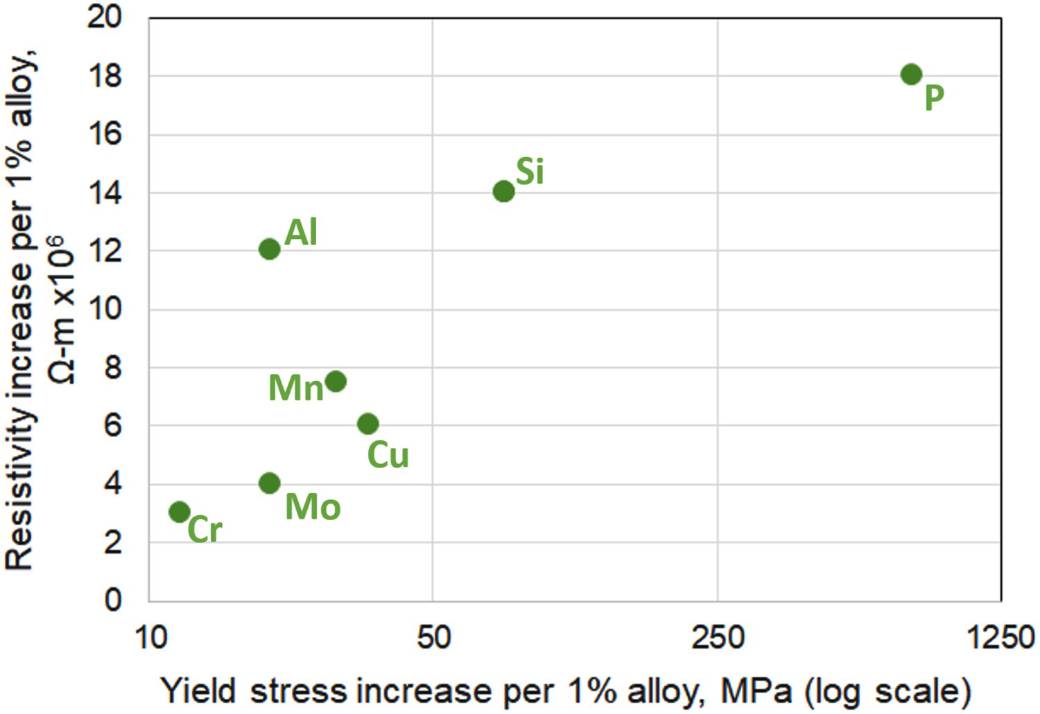
Grain size in steels is well known to affect the strength (principally the yield stress, Rp) according to the Hall–Petch relationship:
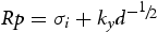
Experimental measurements showing how grain size affects the yield stress of 2.9%Si steel were presented by Douthwaite et al. [12] and are shown here in Figure 4. The expectations of the Hall–Petch model are borne out by the linear relationship between yield stress and the inverse square root of the grain size.
Hall–Petch relationship between yield stress for iron and grain size (mean linear intercept, MLI). For larger grain sizes the yield stress becomes asymptotic to ∼93MPa. Hall–Petch plot showing the variation of yield stress with grain size in a 2.9%Si steel. The measurements span the range of grain size from 30 µm to 300 µm, from ref. [12].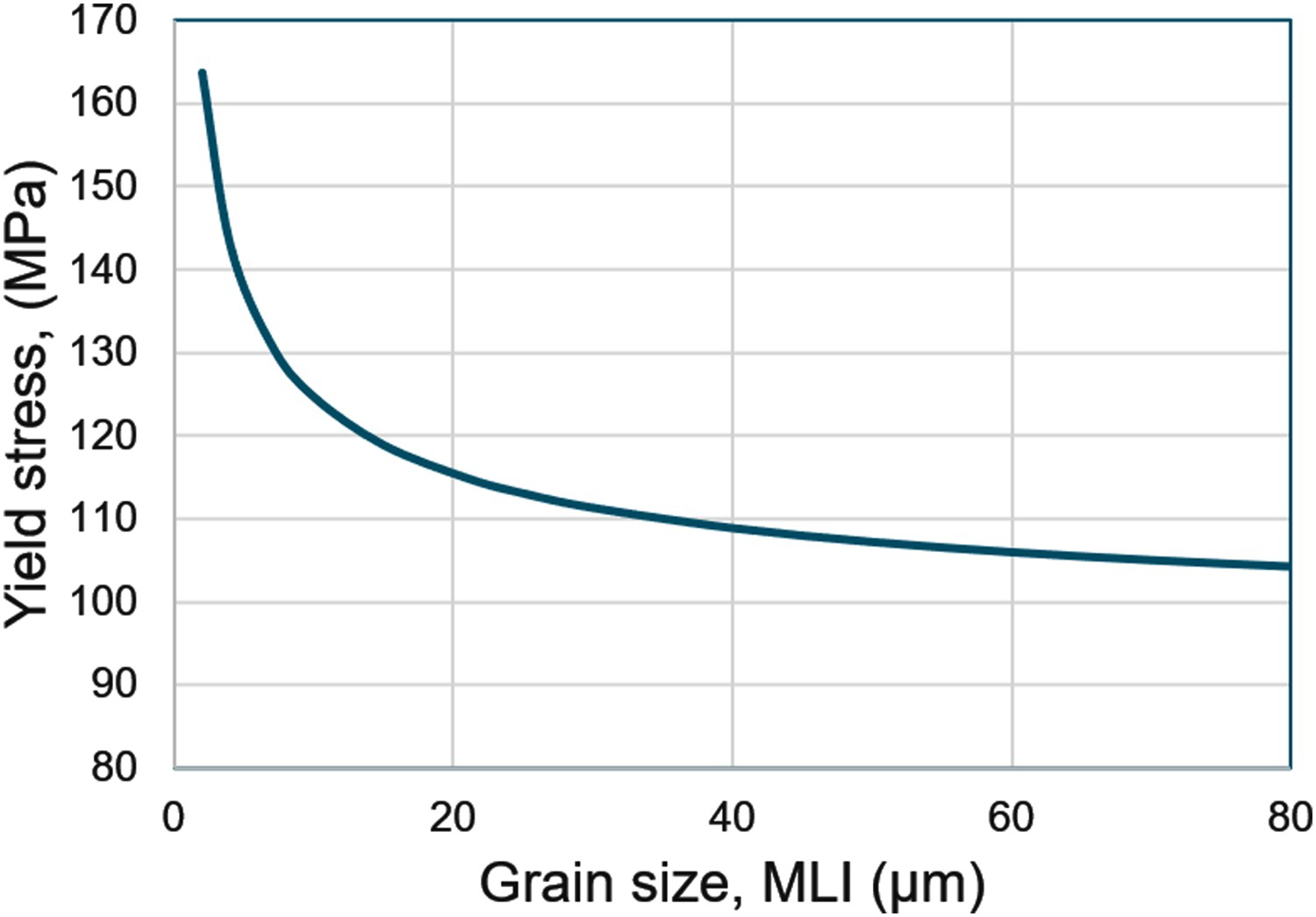
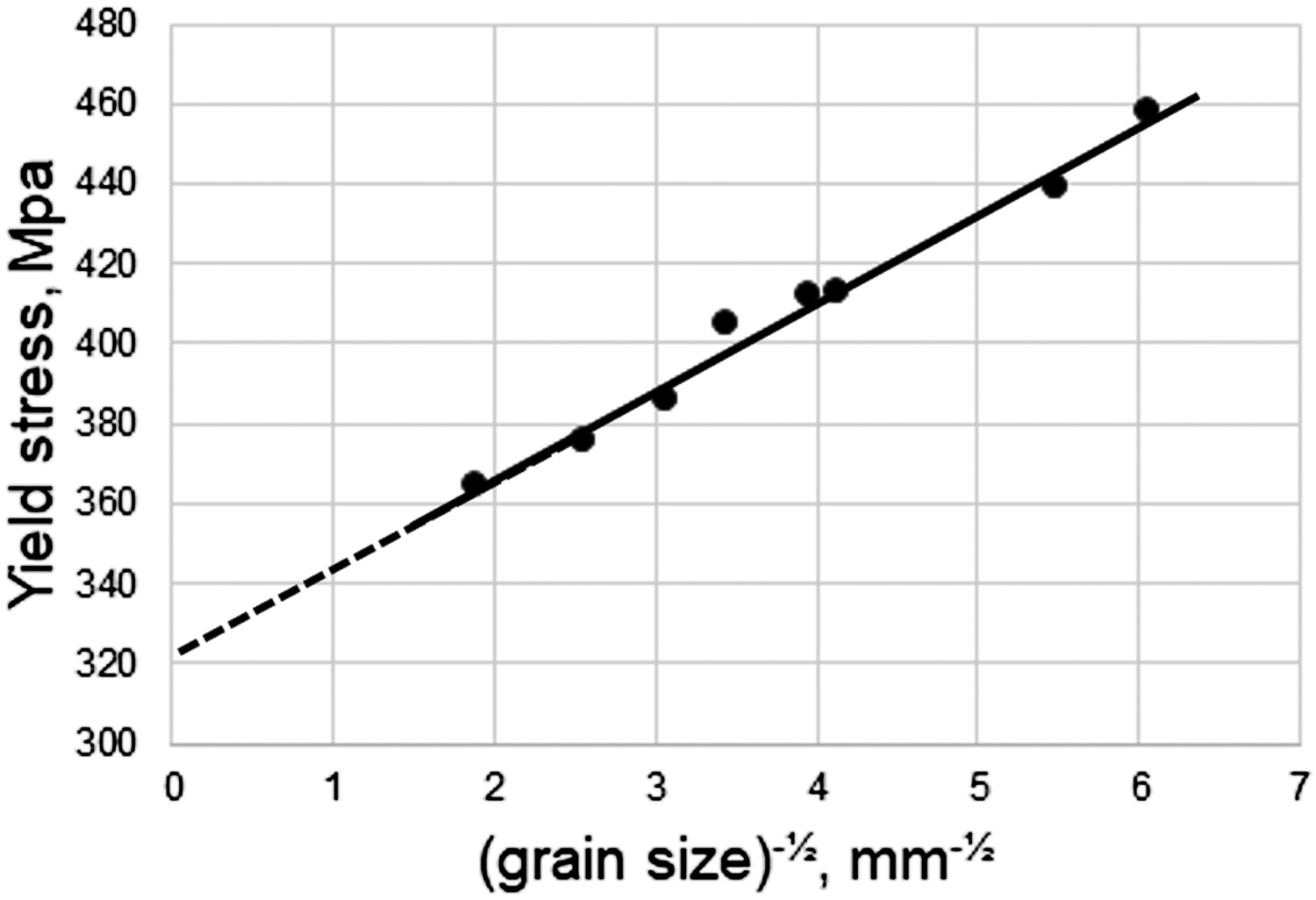
The influence of grain size on power losses has been examined by several workers, e.g. [13-15]. Some approximate relationships for a high-quality electrical steel (3%Si, 1%Al) are given in Figure 5 based on data of Shiozaki et al. [13] together with the analysis given by de Campos et al. [16], for different frequencies of magnetisation. Hysteresis losses constitute a large fraction of the total loss at 50 Hz and domain walls are pinned at grain boundaries which accounts for the increasing power losses with smaller grains, so strengthening by grain refinement is not an option for these conditions. When the frequency of magnetisation is increased, the hysteresis component of loss becomes relatively smaller while the classical eddy current loss increases but the latter is not dependent on grain size. However, anomalous losses also become more important and these decrease with reduction in grain size. There becomes an optimum grains size as also shown in Figure 5 and this optimum grain size becomes smaller as the frequency rises. There is, therefore, some possibility of improving both strength and magnetic quality by grain refinement for high-frequency applications. A full analysis requires consideration of several parameters in combination, not only grain size and frequency but also the sheet thickness and the maximum induction Bmax [14].
Plastic deformation, for example by cold rolling, is a simple and effective way of increasing strength, especially the yield stress. This is due to the rapid increase in dislocation density which is, unfortunately, deleterious for soft magnetic properties. For small strains (<∼10%) dislocation density increases linearly with strain. Since the plastic flow stress varies with the square root of dislocation density the stress–strain curve is approximately parabolic and a strain of 10% leads to an increase in the yield stress of about 100 Mpa. However, straining also increases the power losses as shown in Figure 6 derived from reference [17]. Apart from a very small contribution from the reduction thickness on the eddy currents, this change in total power loss derives entirely from the hysteresis component. It is also shown here that a very small deformation of only 0.5% causes a marked deterioration in the magnetic quality and that further straining has a weaker influence. In general, plastic deformation is undesirable for magnetic quality so work hardening is unlikely to be a viable strengthening mechanism except perhaps for very high-frequency applications where eddy current losses dominate and hysteresis accounts for only a small part of the total loss. However, a combination of work hardening and recovery or partial recrystallisation shows some promise as demonstrated in a subsequent section.
Magnetic power losses as a function of plastic strain (based on ref. [17])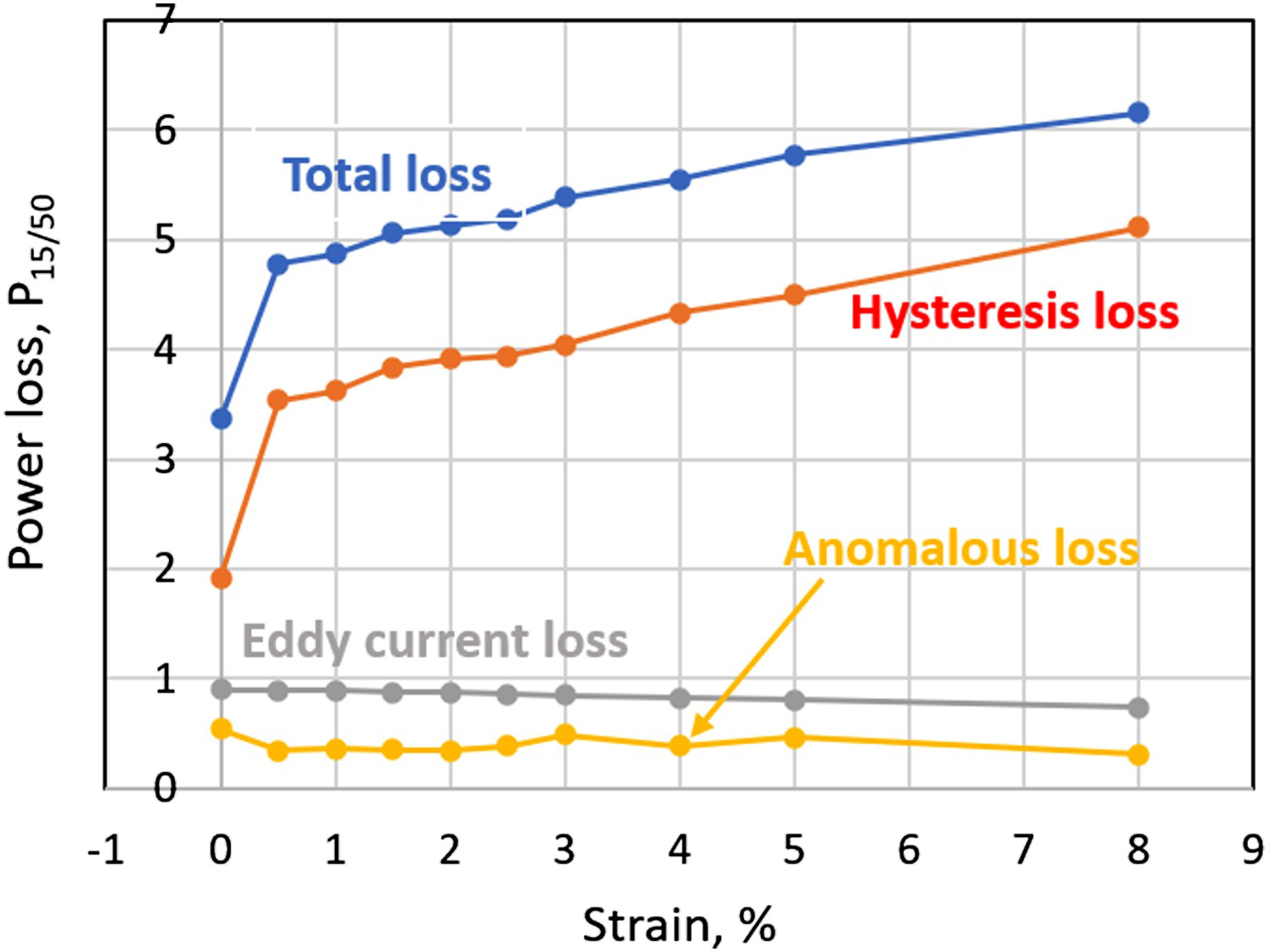
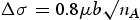
Dispersed second phase particles are well known to raise the strength of metals, especially when they are dense and closely spaced. Plastic flow necessitates the dislocation either to bend between the particles or to shear through them. In the usual case of Orowan hardening where dislocations bow out between particles, the increase in strength Δσ can be expressed as [18]:


Second phase particles also influence the magnetic behaviour since they can pin domain walls, reducing the permeability and increasing the hysteresis losses, e.g. [1-4]. This is well known in practice and serious efforts are made to reduce the impurity elements like S and Ti that create second phases such as MnS and TiN in electrical steels. In some ways this is analogous to the pinning of grain boundaries by particles but there are also differences. For iron, domain walls have a specific energy of about 3 mJ/m2 which is much smaller than for grain boundaries. Domain walls are stabilised at particles because these eliminate some of the wall energy which must be returned if the wall moves, so causing a pinning action, but there is an extra energy term due to the free poles at the particle surface. For larger particles (>∼1µm), closure domains form around the particles to reduce the latter effect.
Another difference between grain boundaries and domain walls is their thicknesses. Grain boundaries have a thickness of approximately 0.5 nm, whereas domain walls in iron spread through some 100 nm from one domain to the next. Small particles (<∼10 nm) are therefore engulfed within the domain walls and cannot drag them in the same ways as happens with grain boundaries. The domain walls do not then behave flexibly which greatly reduces the drag on their movement. This opens an interesting possibility for microstructures that raise mechanical strength without serious detriment to the soft magnetic properties. Since the effect of particles applies to the hysteresis component of loss, this sort of development is particularly relevant to lower frequency operations where hysteresis causes the major part of the power losses.
Texture or preferred crystallographic orientation is always very relevant to electrical steels since magnetisation is easiest along the 〈100〉 directions of the crystals. Relationships between texture and power loss have been proposed in different ways [19,20] but these lead to very similar predictions. The A-parameter described by Kestens [20] is simply the (average) angle between the magnetisation direction and the nearest 〈100〉 direction in the crystals which thus relates to the dominant Stage II part of magnetisation. The value of A can vary from 0° up to 55° but average values are typically 20°–30° depending on the texture. Texture or orientation affects hysteresis but not the other sources of power loss. Grain orientation and texture also influence the yield stress and hence the strength of the steel which can be quantified in terms of the Schmid factor in the law of critical resolved shear stress. If the Schmid factor is small, slip is difficult and the strength is greater. A comparison between mechanical and magnetic orientation dependence can readily be made, assuming that the same direction in the metal applies to both. In Figure 7, the A-parameters and Schmid factors for a wide range of possible grain orientations are plotted together. It can be seen that there is considerable spread without a strong correlation but also that no crystal directions are simultaneously beneficial for both conditions. For steels, it is, therefore, not possible to tailor the texture in such a way that will improve both.
Plots showing the distribution of magnetic A-parameters and mechanical Schmid parameters for 300 randomly selected crystal directions.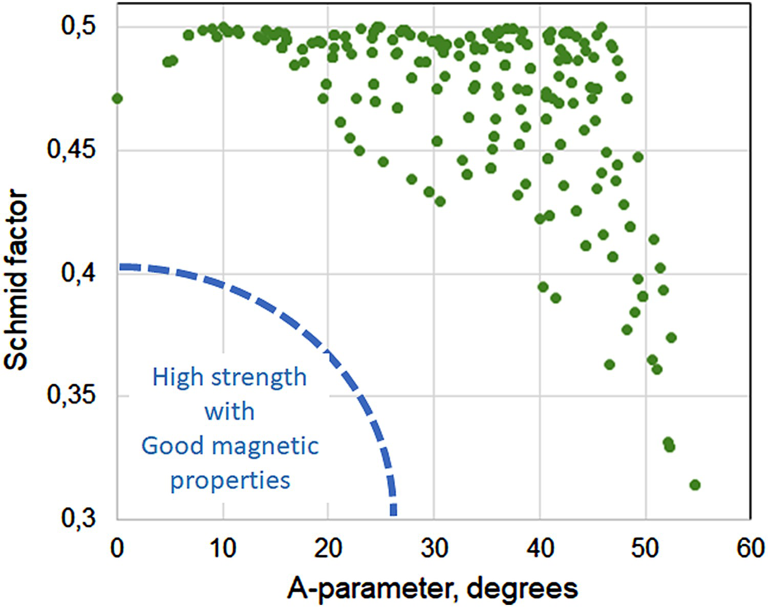
State of the art
The apparent conflict between mechanical and magnetic properties, along with the demands for increases in the mechanical and magnetisation performance of motor components, have in recent years led to a good amount of both academic and industrial interest in studies regarding different strengthening mechanisms and their relationships with magnetic properties.
Solid solution strengthening
Typical tensile test properties for various grades of commercial non-oriented electrical steels.
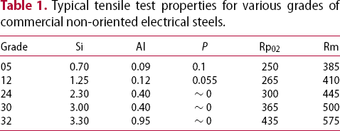
Brittleness aside, solid solution strengthening remains in many ways an excellent route towards improving strength while maintaining good magnetic properties, considering that alloying typically raises the resistivity of the material, so reducing the effect of eddy current losses during cyclic magnetisation. Figure 8 shows the effect of Mn, Ni and P additions to the yield strength of a 3%Si electrical steel alloy as determined by Kubota et al. [24]. In their study, no significant alloying effect was observed on the P15/50 core loss, nor was the induction changed with the Ni and P additions.
Effect of Mn, Ni, and P additions on the yield strength of a 3%Si electrical steel alloy [24].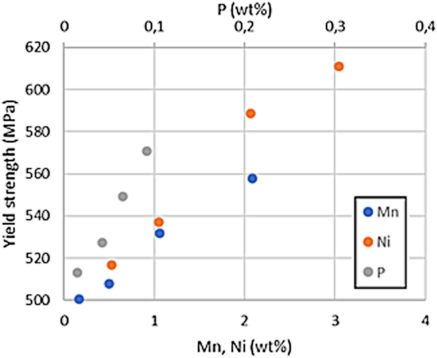
One concern when alloying electrical steels is the tendency of most typical alloying elements in steel (apart from Si, Al, Cr, Mo and P) to increase the stability of the high-temperature austenite phase. Mn and Ni are effective austenite stabilisers and some care should be taken when they are added to compositions to ensure that high-temperature final annealing remains possible without the risk of austenite formation which leads to undesirable grain refinement. Schulte et al. [25] showed that a Mn addition of 1.4–2.6%Si electrical steel should, according to their thermodynamic calculations, result in the formation of austenite at temperatures above approximately 900°C. However, dilatation curves measured at a heating rate of 1.8K/min showed no phase transformations when heating to 1150°C. They observed the effect of Mn on yield strength to be consistent with the studies of Kubota et al. [24]
Dislocation strengthening
As discussed above, an increase in dislocation density results in an increase in strength, together with a corresponding increase in the hysteresis loss component of the total power loss. This trade-off in properties has been justified based on the different property requirements of the stator and rotor components of electric motors. In high-speed electric motors of the IPM-type, the rotor component is typically exposed to high mechanical stresses while the demands for its magnetic properties are only moderate. Conversely, the stator is not highly stressed but is required to have the lowest possible magnetic power loss. Since there are economic benefits in producing both of these components from the same sheet, it is of interest to develop process routes where both of the requirements can be achieved.
Tanaka and Yashiki [26] have shown that, although the dislocation strengthening mechanism degrades magnetic properties, the core loss remains at only a third of that observed in more conventional high-strength steels. In their study, the dislocation strengthening effect was achieved by controlling the recrystallised fraction formed during final annealing of the steel.
Much experience in the steel industry has shown that ‘back-annealing’ to produce desired microstructures and properties is quite difficult to achieve reproducibly. Small deviations in steel chemistry as well as in the prior grain microstructure can have strong influences [27], although alloy additions have been found to buffer such effects. Specifically, it was shown by Tanaka and Yashiki that alloying small amounts of Nb to electrical steel retards the recrystallisation process. Various other patents have been filed demonstrating different methods of obtaining a dislocation strengthening effect on electrical steels, either by controlling the final annealing treatment after cold working [28-30] or in conjunction with heavier alloying additions [23], [31].
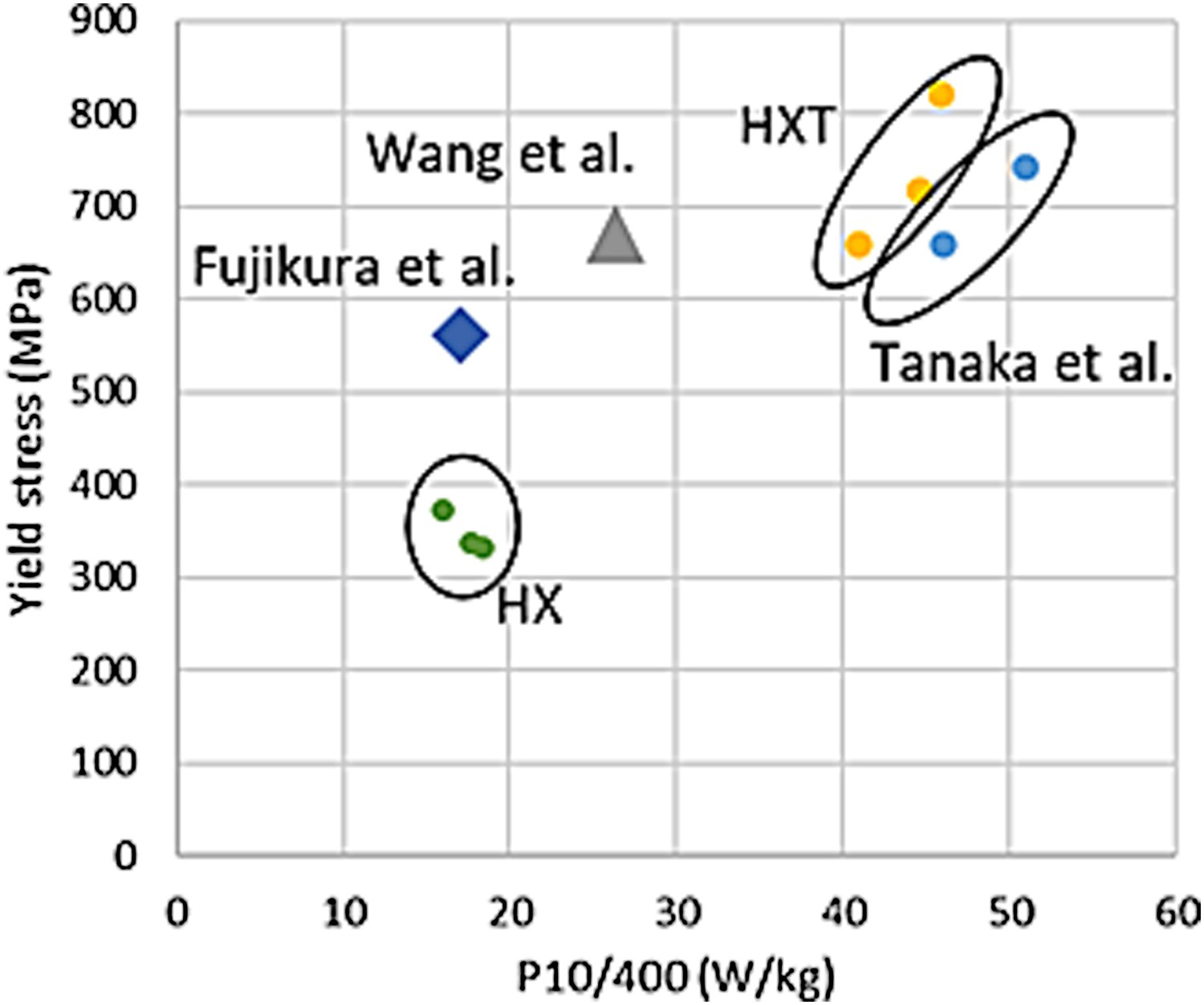
Figure 9 shows the reported tensile strengths and P10/400 power loss values for various electrical steel alloys rolled into 0.35 mm steel sheets in which dislocation strengthening was employed. In this figure, the properties of commercially available non-oriented electrical steels are represented by Nippon Steel's HX and HXT (high-strength) product lines, of which HXT shows nearly equivalent properties to those presented by Tanaka et al. [26]. The Figure shows that in the case of dislocation strengthening, core loss invariably increases with the yield strength of the material.
Typically, the resulting microstructure in dislocation-strengthened steel is a mix of recrystallised grains and the remaining deformed structure, in which the recrystallised grains provide a good magnetic response and the deformed structure provides increased strength. Zhang et al. [23] showed an inverse linear correlation with the recrystallised fraction, power loss and yield strength in a cold-rolled Fe–4.5%Si alloy sheet, Figure 10. This would imply that a relatively simple constitutive model could be used for predicting the yield point and core loss when recrystallisation control is used as a strengthening mechanism.
The microstructure of a Fe–4.5%Si steel cold rolled to 0.15 mm and annealed at (a) 600°C, (b) 590°C, (c) 580°C, (d) 570°C, (e) 560°C and (f) 550°C, as well as (g) the yield strength and core loss at P10/400 plotted against recrystallised fraction. Reproduced from [23].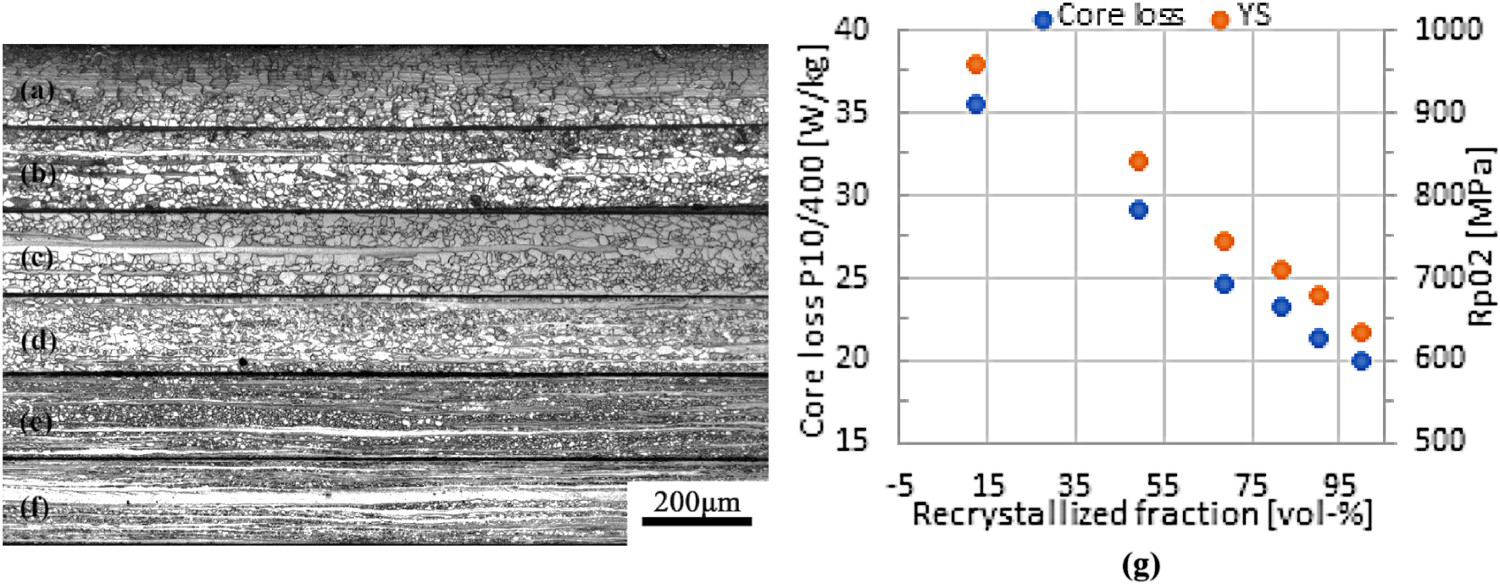
Nanoparticle strengthening
The effect of copper nanoparticles on electrical steel strength and magnetic response has been under some study during recent years [32-37], in addition to which a patent has been filed by Nippon Steel Corporation outlining some industrially viable production routes for electrical steel strengthened in this manner [38]. Takahashi et al. [32] showed that for a ferritic Fe–0.0012C–0.096Mn–1.40Cu steel, it is possible to increase yield strength significantly due to particle strengthening by aging the solution annealed and quenched material at 500°C. Transmission electron microscopy (TEM) and atom probe tomography (APT) studies on specimens aged for various times showed gradual nanoparticle growth until a 3 nm particle size had been reached after 4 h of aging. For longer times, the structure of the particles changed from coherent body-centred cubic (bcc) to semi-coherent 9R structure in the 4–6 nm size region, after which particle growth was more rapid. The peak aging effect was reached at 2 h with the particles still in the bcc structure and maintained until 16 h of aging, after which the yield strength was observed to decrease, along with more rapid growth of particle size and transformation of the bcc structure to the intermediate 9R structure. Before transformation to the 9R structure, after approximately 8 h, the authors reported that no contrast between the precipitates and the matrix could be observed in TEM bright-field micrographs, necessitating the use of APT to characterise the precipitates before the 9R transformation. The transition of the particles is shown in Figure 11, where a 16 h aging treatment results in visible precipitates in bright-field images, while at 8 h, the precipitates can only be detected in the 3D-APT copper maps.
The evolution of copper precipitate structure and morphology in a Fe–0.1Mn–1.4Cu steel during aging at 500°C, shown as (a) 3DAPT copper maps and (b) TEM bright-field images. The transition of the precipitates from a BCC to a 9R structure is marked by the particles showing contrast in the bright-field image. Reproduced from [32].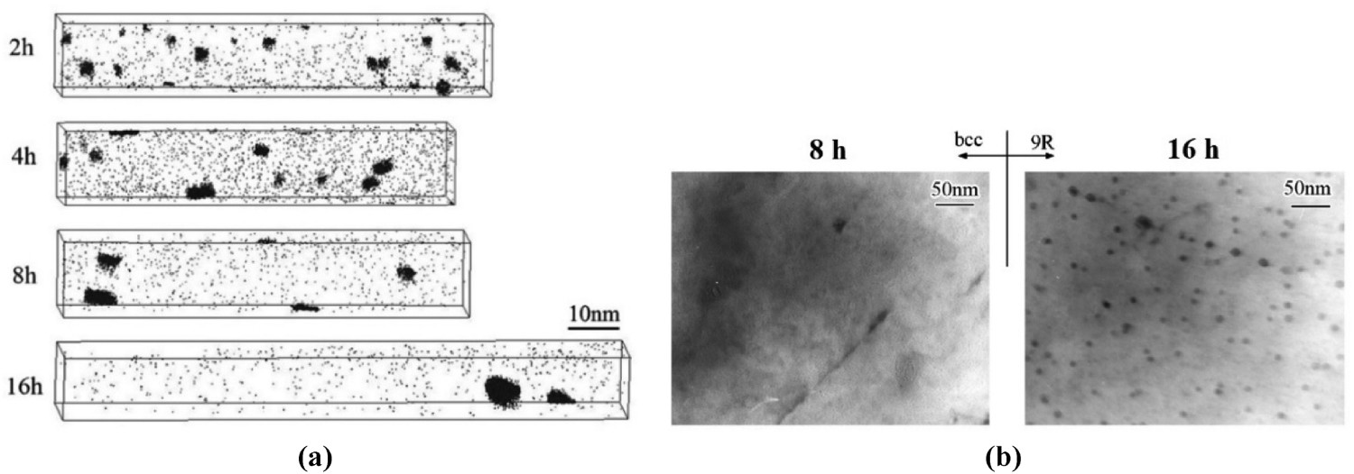
Fujikura et al. [34] conducted overaging treatments at 700°C and 750°C with various aging times to study copper nanoprecipitate growth during extended aging periods. The alloying composition they studied included 3% Si and 1.2% Cu, cold rolled to 0.35 mm and recrystallised to a ferrite grain size of approximately 80 µm before aging. They showed that after extended holding times at these higher temperatures, the particles appear to grow following the Ostwald ripening mechanism, with the mean diameter of Cu precipitates correlating with the cube root of aging time. The hysteresis loss component was observed to increase with precipitate growth until a precipitate size of approximately 70 nm after aging at 700°C for 20 h. Aging at 750°C for the same time resulted in a precipitate size of approximately 270 nm, which resulted in lower hysteresis losses. Fujikura et al. showed that this effect on hysteresis loss appears to follow the relationship proposed by Dijkstra and Wert [39] when the precipitate size far exceeds the size of magnetic domain wall thickness in the material.
In the same study, Fujikura et al. [34] showed that it is possible to increase the yield strength of electrical steel by copper nanoprecipitation, while maintaining low core loss. They modified the aging temperature, holding the material at temperatures between 400 and 700°C for 1 min. Peak aging response was at aging temperatures 500–600°C, with an increase of approximately 120 MPa in yield stress after aging for 1 min compared to the unaged condition. Figure 12 shows the hardening response with respect to aging temperature, as well as the effect of nanoprecipitate size on P10/400 core loss. This clearly shows that a nanoprecipitate size of approximately 10 nm and below does not increase core loss, while a size of 40 nm already results in a significant increase. As discussed previously, it appears that a sufficiently small nanoprecipitate size is the critical factor that prevents the pinning down of domain walls during cyclic magnetisation.
(a) The yield strength of an electrical steel composition containing 3% Si and 1.2% Cu with respect to 1 min aging at various temperatures and (b) The core loss P10/400 versus precipitate diameter. Reproduced from [34].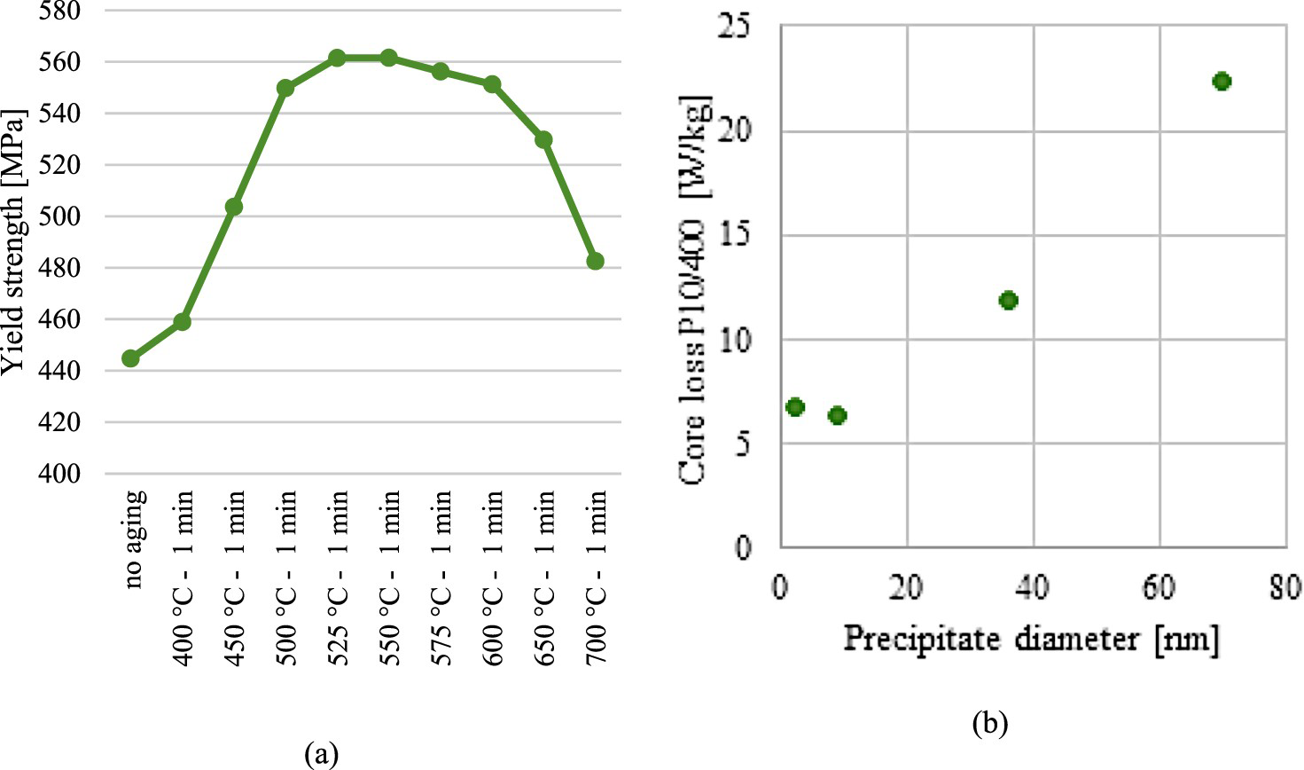
Wang et al. [36] showed a similar strengthening effect of nanoparticles for a Fe–0.2Mn–3.2Si–1Ni–1Cu–0.23Al electrical steel alloy cold rolled to 0.35 mm and annealed for a ferrite grain size of approximately 40 µm. Peak aging condition was reached after 25 min at 550°C, with approximately a 150 MPa increase in yield point with no increase in total loss at P15/50. Figure 9 shows the tensile strength and P10/400 power loss value reported by Wang et al., along with the same properties measured by Fujikura et al. It is notable that both these nanoprecipitate-strengthened steels exhibit strength levels comparable to the dislocation-strengthened materials, while the core losses remain approximately at the level of the conventional electrical steels. It is also worth noting that all of the electrical steels in Figure 9 were rolled to a thickness of 0.35 mm and annealed to a ferrite grain size in the 40–80 µm range, making the results roughly comparable to each other.
In addition to copper nanoprecipitate aging, some commercial work has been conducted on Fe–Si–Zr and Fe–Ti–P precipitates [40,41], although the reported property combinations did not show significant improvements over conventional alloys.
Conclusions
It can be concluded that while the development of high-strength non-oriented electrical steels has been making slow but continuous progress through the last few decades, there is also a significant amount of prior work to build upon. The effect of conventional electrical steel alloying compositions on both strength and magnetic properties has been studied exhaustively throughout the last century and up until recent years. The effect of grain size has been similarly studied with considerable interest for over 50 years, with the focus of studies shifting towards higher-frequency magnetisation cycles as the demands set by advances in electrical motor technology have increased. The optimisation of crystallographic texture, while also extensively studied, has been focused exclusively on reducing core losses during cyclic magnetisation. As shown earlier, the optimisation of both magnetisation response and strength by texture manipulation is not possible simultaneously in the same material.
The current state of the art at the commercial level appears to be shifting towards the use of dislocation strengthening to produce a controlled combination of mechanical and magnetic properties. This method, however, is constrained to a rigidly defined range of properties where the conflict between magnetic and mechanical performance is not resolved.
Nanoprecipitate aging, on the other hand, appears to offer a way to increase strength without adversely affecting core losses during high-frequency cyclic magnetisation. This method has been under continuous academic study since being introduced in a patent by Nippon Steel Corp. in 2004. The cited studies have focused almost exclusively on the effect of copper nanoprecipitates. Along with the demonstrated impressive combinations of low core losses and high strengths, the virtue of copper alloying appears to be a relatively robust response of the materials to realistic hardening temperatures and times from an industrial perspective. In the light of the explosively growing usage of electrical motors in the transport sector and the consequently rising performance requirements, it is not unreasonable to expect that electrical steels benefiting from this strengthening mechanism will enter commercial use at some point in the near future.
Footnotes
This work was partially financed by the Swedish Energy Agency (Energimyndigheten FFI/Energi & Miljö) innovation program research fund, project nr. 51455–1
Disclosure statement
No potential conflict of interest was reported by the author(s).