
Abstract
Steel with 2.4–2.5 GPa tensile strength and elongation to fracture of 4.8–5.7%, is produced by designing a novel heat treatment identical to quenching and tempering, in less than a few minutes. Since addition of Si to Fe–Mn steel promotes the austenite stabilisation by carbon enrichment, the elongation to fracture of 0.6C–1.6Si–1.2Mn (wt-%) steel treated by different quenching and partitioning (Q&P) routes is improved. Results demonstrated by process control maps give a good overview of the final microconstituents. By using higher partitioning temperatures, the tempering of martensite, stabilisation of austenite and improvement of the mechanical properties, could effectively be accelerated. This approach results in significant time and cost reduction which makes this heat treatment attractive for industries.
Introduction
Ultra-high strength steels with good ductility are highly demanded and have been developed in recent years in order to design lighter components and decrease the energy consumption and environmental impact [1–5]. Increasing carbon content to medium or high level (>0.5 wt-%) as the primary alloy for steels with higher strength and hardness is usually the most economical approach to achieve extreme properties. However, high-carbon martensitic steels are ‘as brittle as glass’ in the as-quenched or low-temperature-tempered state [6]. When the limited ductility and toughness can be tolerated, the excellent strength and hardness of high-carbon steels could be utilised. Common applications of high-carbon steels include rail steels, spring steels, wear resistant steels, forging grades, wire rope, tire reinforcement, pre-stressed concrete, and high strength bars [7].
Many attempts have been performed in order to develop such ultra-high strength steels without losing the ductility. The most typical class is ‘maraging’ steels which contain carbon-free martensitic matrix with nanoprecipitates, but these steels are highly alloyed with Ni (8–18), Co (4–15), Mo (1–5) wt-% and Ti, which limits their applicability due to their price. For instance, C530 in this group has the highest strength of 2.4 GPa and 7% ductility. On the other hand, tempering of martensitic steels has been widely studied during the last 50 years [8,9]. For example, a modified version of the 100Cr6 (AISI 52100, a 1C-1.5Cr wt-% bearing steel) was developed in the late 1990s to exhibit higher retained austenite contents by adding Mn and Si to the chemical composition [10,11]. The original 100Cr6 has a high tensile strength of 2 GPa, but very low elongation of about 1–2% [12]. Basically, retained austenite is often undesirable in standard 100Cr6 steel because of its low thermal and mechanical stability which makes it susceptible to rapid decomposition (a few hours) at temperatures as low as 200°C [13–15]. By adding Mn, the martensite start temperature is lowered, while Si additions help further stabilisation of retained austenite. Previous investigations on low austempering temperatures (125–350°C) of high-carbon high-silicon steels provide comprehensive information on the kinetics of austenite decomposition into bainite [7,16–21]. The main purpose of using low temperature austempering is to allow the development of a mixture of very fine bainite laths with retained austenite but this requires tens of hours at 250°C or lower temperatures. Comparing yield strength of different microconstituents, the martensitic structure has the highest yield since strain-induced martensitic transformation from retained austenite relieves the stress within untransformed retained austenite and gives rise to stress redistribution also in its adjacent ferrite laths during deformation [22]. So, Quenching and Partitioning (Q&P) steels show one of the best mechanical properties among low carbon steels (C < 0.3 wt-%). However, the formation of brittle twin-type martensite [23–25], as well as the instability of carbon enriched retained austenite [22] are detrimental for the ductility and toughness of steels. In order to enhance the ductility of high-carbon martensitic steel, the basic approach is to utilise dispersed carbon enriched retained austenite to replace bulky retained austenite [25]. In addition, recent findings [6,26] showed that decreasing the number of coarse martensite plates can effectively increase the ductility. Wang et al. [27] have decreased the austenite grain size by applying severe plastic deformation (ε = 90%) above A3 and quenching the sample to room temperature. Thereafter, heating the sample to 500°C and holding it there for 1 h, applying the second deformation (ε = 85%) followed by quenching and finally performing the heat treatment by austenitisation, water quench and low temperature tempering. Although this thermomechanical treatment is long and costly, ultra-fine austenite grains of 2.4 μm and 2.6 GPa ultimate tensile strength (UTS) with 7% elongation is obtained.
Recently, Sourmail et al. [13] have designed a new heat treatment based on the fact that pre-existing martensite shortens the required duration for bainitic transformation [28–30]. So, the process is basically quenching and tempering of a high-carbon high-silicon steel (1C–1.25Si–0.96 Mn wt-%) but the tempering temperature is selected to be sufficient (300°C) to complete the bainite reaction in a few hours. In comparison with austempering, the quenching and partitioning (Q&P) treatment has much higher transformation rate. Basically, Q&P starts with a first controlled quenching to a temperature between Ms and Mf after fully or partially austenitisation. This quench defines a specific fraction of initial martensite, and then a holding of the component at a usually higher temperature for some time gives enough energy for tempering the ‘initial martensite’ and partitioning of carbon from martensite to retained austenite. Subsequently, the process finishes with a second quench which may lead to the formation of ‘secondary martensite’ (fresh martensite) [31,32]. Owing to weldability requirements, 90% of all steels used today are alloyed with less than 0.2 wt-% C [33]. Therefore, there is still a large lack of information on high-carbon steels in comparison with low carbon steels.
In this work, the concept of quenching and partitioning based on the understanding of the microstructural evolution of high-carbon high-silicon steel has been used to design a new heat treatment route. Owing to that fact that silicon retards the austenite decomposition into bainite by promoting carbon partitioning from martensite into austenite and increasing austenite stability during the partitioning stage [34,35], high partitioning temperatures for a few seconds have been compared with lower temperatures but longer times. The goal has been to compare the effect of different Q&P conditions and to provide a process map in order to elucidate the microstructural evolution and give the opportunity for the consumer to select the heat treatment conditions based on the desired properties.
Experimental procedure
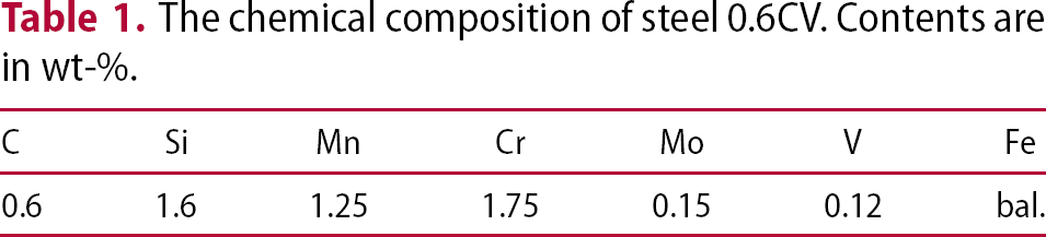
The chemical composition of steel 0.6CV. Contents are in wt-%.
Gleeble 3800 has been used to perform different heat treatments on samples with the size of 10 × 10 × 75 [mm3]. These were used to analyse the microstructure (Section ‘Microscopy’), fraction of phases (Section ‘XRD Analysis’), hardness (Section ‘Hardness’) and impact toughness (Section ‘Impact Toughness’). A fully austenitisation at 890°C for 5 min was performed for all samples, while different quenching and partitioning conditions were applied (Figure 1) Three different quenching temperatures (190, 165, 25°C) were selected, which results approximately in 30, 50 and 85% of martensite after the first quench (Ms = 223°C; Mf = 99−195°C). Partitioning conditions in order to achieve similar levels of carbon enrichment of austenite, based on carbon diffusivity (discussed in section ‘Discussion’, Figure 12) were selected. So, a total number of 48 conditions were analysed as shown in Figure 1, where QT, PT, and Pt refer to the quenching temperature, partitioning temperature and partitioning time, respectively.
Schematic illustration of the Q&P conditions evaluated. PT and Pt refer to partitioning temperature and partitioning time, respectively.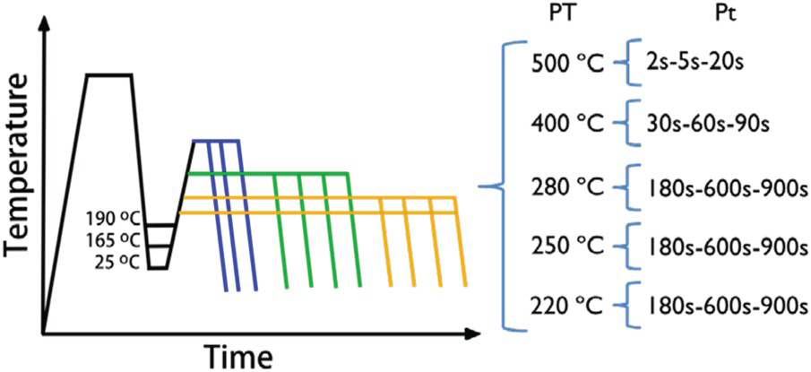
The terminology of the samples is QTX-PTX-PtY, where X and Y denote the temperature (in Celsius) and time (in seconds) used during the different steps of the heat treatment.
Concerning the process maps, the experimentally tested partitioning temperatures and times were used to construct each process map. Any other information outside these values is a result of a linear inter/extra-polation based on the experimental obtained values made with OriginPro 2017 (Colour Fill tool).
Microstructure characterisation
A polished surface for each sample was prepared by conventional manual grinding and polishing step by step up to Colloidal silica of 0.06 µm for the final stage, to reveal the microstructure for optical microscopy, SEM, EBSD, XRD and to evaluate the microhardness.
Microscopy
The optical microscopy (OM) analysis was carried out using Nikon Eclipse MA200. LePera colour etching [36] was utilised to reveal and distinguish initial martensite (tinted in blue) from bainite (brown), while either retained austenite or fresh martensite do not etch and can be observed as white. Samples QT165 and QT190 were etched during 15–20 s, while 30 s was necessary for specimens quenched until room temperature based on the variation in the amount of initial martensite. JEOL JSM-IT300LV scanning electron microscopy (SEM) and FE-SEM Helios Nanolab 600 (FEI company) have been used for higher magnification microscopy and EBSD, respectively. The ARPGE [37] software was also used to post-process the EBSD results to construct the parent austenite grains.
XRD analysis
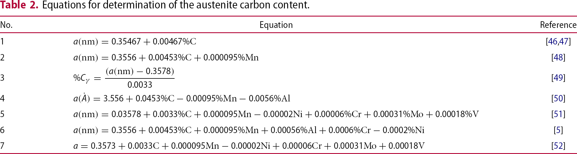
X-ray diffraction test to determine the fraction of phases and austenite carbon content has been performed on the transversal cut samples by using Panalytical Empyrean diffractometer, collecting data from 40° to 100° () with a step size of 0.013°, and a scan speed of 0.026796° s–1, on the cross-section of the sample. HighScore Plus v. 4.7 software and PDF4 database were utilised to perform Rietveld analysis [38] to find the lattice parameters for calculation of the retained austenite carbon contents.
Mechanical properties
Hardness
A Matsuzawa MXT microhardness tester with a load of 5 N (HV0.5) was utilised to study the Vickers hardness (HV) variations of the samples. This load was selected in order to obtain an indentation size with a diagonal larger than 25 µm, so that all microconstituents present in the microstructure could be covered by the indentation.
Impact toughness
Dimension of the samples is according to ASTM Standard E 23. The Charpy V-Notch Impact Tests were carried out at room temperature and the energy absorbed during the test is reported in joule (J).
Tensile test
The austenitisation was carried out at 890°C for 1 h based on NANOBAIN project results [17] using a Nabertherm N11/H batch furnace. The quenching stage was performed in either Therm Concept salt bath (for QT190 and QT165) or oil (for QT25).
Samples quenched until 190 and 165°C were held in the salt bath for 1 min, in order to stabilise the quench temperature in the sample and directly afterward, they were heated to the respective partitioning temperature by moving them to a second salt bath. On the other hand, for samples quenched until room temperature, the oil was removed from the sample surfaces before they were partitioned in the salt bath. All the samples were cooled down in calm air after the partitioning. Owing to austenitisation in an air atmosphere, the decarburised surface layer of samples was 400 µm, revealed by hardness (HV0.1) as a function of the distance from the surface measurements. So, as shown in Figure 2, samples were ground to remove the decarburised layer before the test.
Shape and layout of tensile test samples (a) As-machined (b) After heat treatment (c) After grinding (d) Layout of specimens.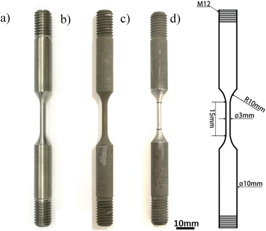
Tensile tests were carried out at room temperature using Gleeble 3800 and the strain rate applied was 0.005 s−1.
Results
Phase fractions
Based on the quenching temperature, which implies the amount of initial martensite, the final content of retained austenite at room temperature changes. Figure 3 shows the ‘constrained carbon equilibrium’ (CCE) model [39] in order to illustrate the influence of QT on the phase fraction of different micro constituents of the final structure. Since the assumption in this model, is that all the trapped carbon in the initial martensite will diffuse out and dissolve evenly in the retained austenite during the partitioning stage, it will overestimate the amount of retained austenite. This will still be useful in order to find the optimum QT, which has the highest potential to result in the highest retained austenite content [40].
Theoretical evolution of the microstructure of the 0.6CV vs quenching temperature.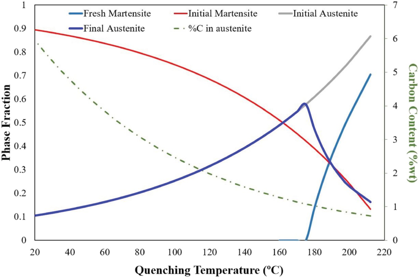
The importance of adequate characterisation technique for complex phase steels and their accuracy is obvious, and the quantitative measurement of phase fractions is not an easy task. The difference in the results achieved by established techniques like light microscopy, XRD and EBSD makes this more challenging. Comparisons between different techniques for determination of the RA have been performed for TRIP [41] and stainless steels [42]. No preferential technique has been found by round robin tests performed in these comparisons. Nevertheless light microscopy and EBSD systematically over- and under-estimate the amount of RA, respectively.
Light optical microscopy (LOM)
Figure 4 shows colour etched microstructures of different Q&P treated samples at different conditions. This method can well discriminate the phases based on their colours which subsequently will be used by the image processing software to quantify the fraction of phases.
Example of the different microstructures according to the quenching temperature. (a) QT200-PT220-Pt600, (b) QT165-PT500-Pt5; and (c) QT25-PT400-Pt60 (Magnification: 1000x-Samples tint etched with Lepera method, to be able to see the phase colors please refer to digital version).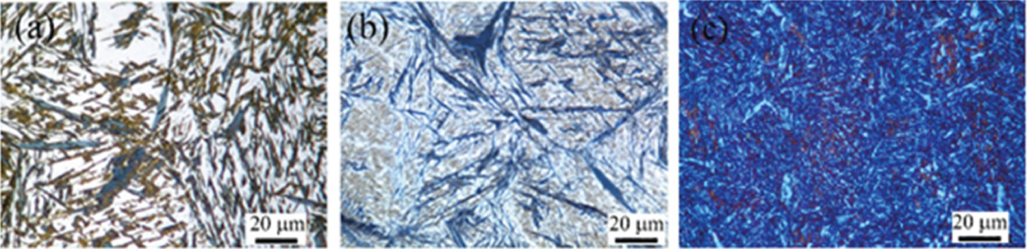
Since both retained austenite and fresh martensite appear as white, high magnification EBSD with a very small step size of the beam could clarify the difference between them and help to compare the image analysis results of LOM with EBSD.
Electron backscatter diffraction (EBSD)
Figure 5 shows the EBSD results of the sample shown in Figure 4(b). In this picture image quality (IQ) and phase map are superimposed on each other. All body-centred cubic (BCC) structures are coloured as red but higher tetragonality of BCT structure and dislocation density of martensite decreases the quality of the Kikuchi patterns [43,44]. Consequently, initial martensite is brighter than fresh martensite/bainite. So, Figure 5, shows that most of the austenite is located just around the tempered martensite and the lathes which are darker are fresh martensite. In this regard, image analysis of the LOM results should be performed at the highest magnification of the optical microscope (1000x) and with high consciousness not to overestimate the fraction of retained austenite [41].
Superimposed image quality map and colour-coded phase map of sample QT165-PT500-Pt5. Austenite appears green. Regions of tempered or fresh martensite/bainite all appear red, but the brighter regions are likely tempered martensite while darker greyscale indicates regions are likely martensite/bainite (For interpretation of the references to color in this figure legend, please refer to the web version of this article).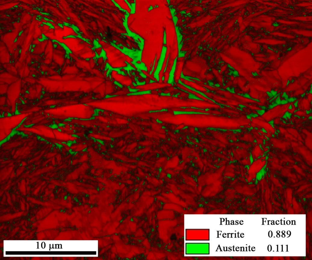
It is clear in this picture (Figure 5) that initial martensite (bright red) is formed mostly as plate martensite. Figure 6(a) shows the Image quality map and Figure 6(b) the Kernel average misorientation (KAM) map located on one parent austenite grain, which is reconstructed by ARPGE software. Figure 6(c) shows the grain boundaries of parent austenite grains and Figure 6(d) the inverse pole Figure of that austenite grain. Comparison between them shows that brighter parts of Figure 6(a) demonstrate lower stress level (blue parts) in Figure 6(b) which represent smaller distortion of tempered martensite [45]. In addition, although there are a few lathes of initial martensite in the structure, most of them are plate martensite and oriented along the grain boundaries of parent austenite grains (compare Figure 6(b,c)).
(a) Image quality map and (b) Kernel average map of sample QT165-PT250-Pt600 from its EBSD analysis. (c) Grain boundary map and (d) IPF of reconstructed parent austenite grain by post processing the above EBSD data by ARPGE software.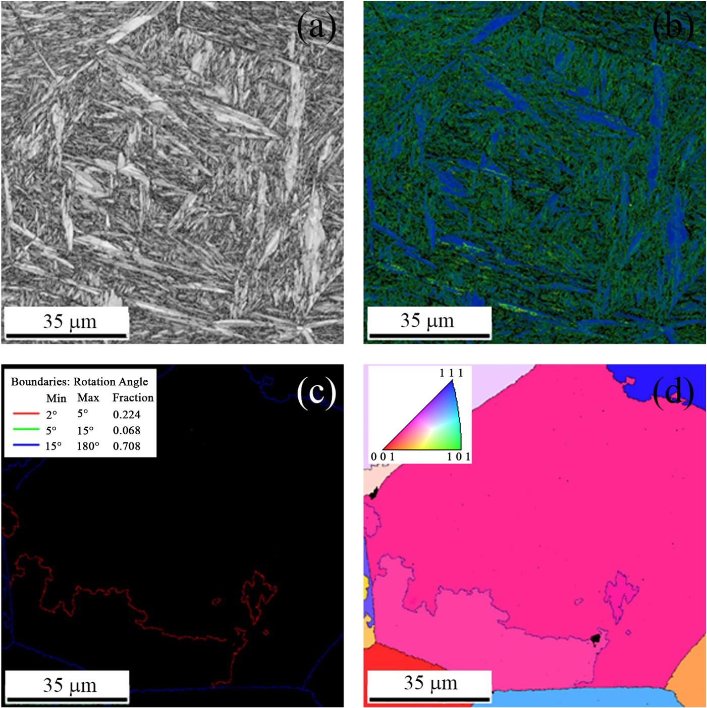
X-ray diffraction (XRD)
Considering the tetragonality of the iron BCC and BCT, and by using PDF4 (2018) database, it is possible to separate fresh martensite from tempered martensite/bainitic ferrite in an integrated XRD-peak.
Equations for determination of the austenite carbon content.
Carbon content range of retained austenite in the samples quenched at a specific temperature but partitioned according to the 15 different routes mentioned in Figure 1.
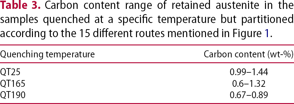
Figure 7 shows the austenite fraction measured by XRD based on quenching temperature for different partitioning times and temperatures.
Colour maps of the changes in the amount of retained austenite (%) after different partitioning times and temperatures for each QT. Analysis via XRD.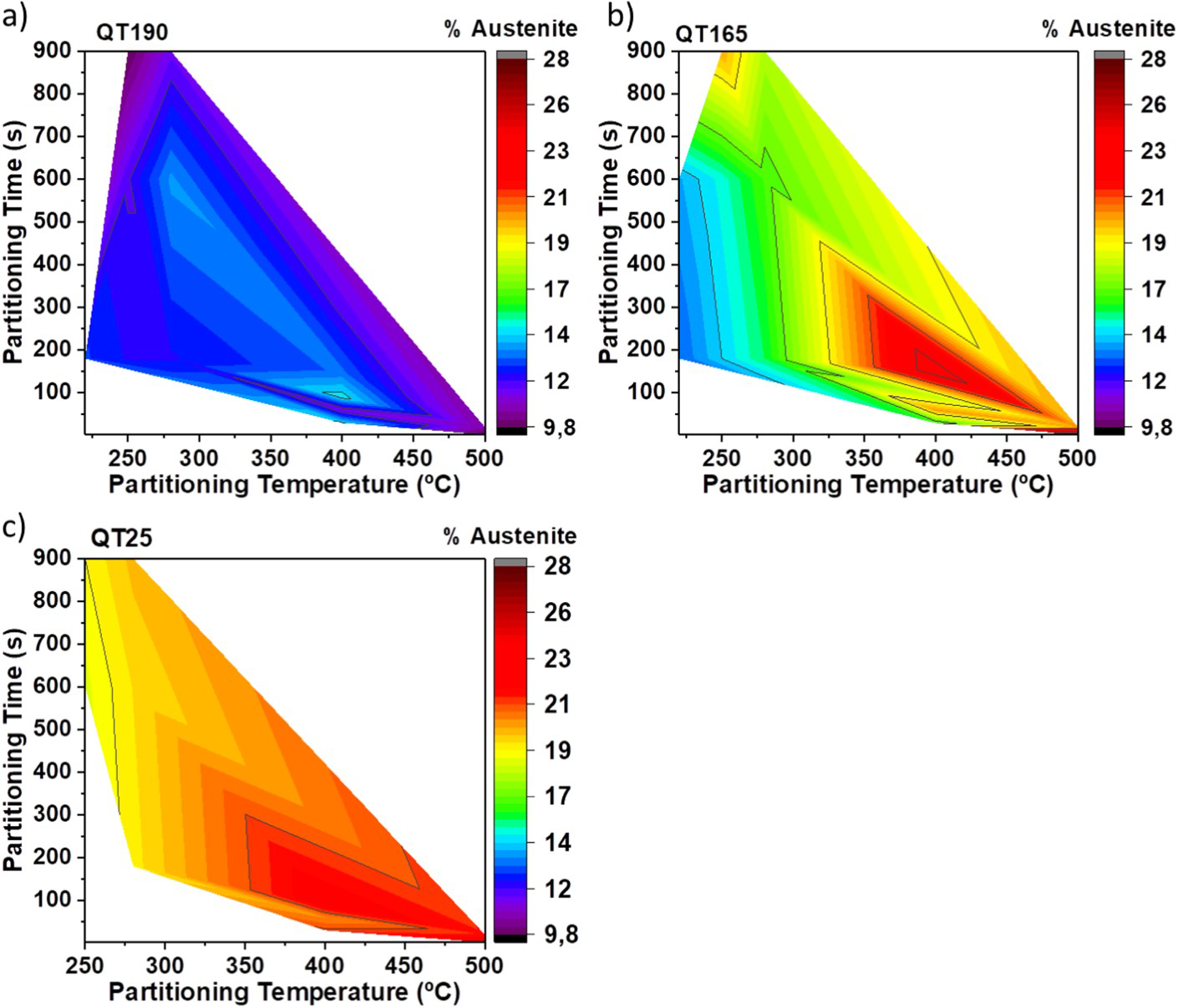
Mechanical properties
Hardness
The influence of different partitioning conditions on hardness is summarised in three different colour maps, one for each quenching temperature (see Figure 8). It is important to highlight that (i) even though samples quenched until room temperature (QT25-Figure 8(c)) have the highest amount of initial martensite, the highest levels of hardness are achieved in QT165 and QT190 (Figure 8(a,b)). (ii) Owing to the high-carbon content distorting the body centered tetragonal (BCT) unit cell of the martensite, plus the high dislocation density, the fresh martensite represents a hard phase in the microstructure. Therefore, higher level of hardness (approximately, 800 HV) confirms the presence of fresh martensite as the hardest microconstituent, in QT165 and QT190 samples. (iii)The location of the lowest levels of hardness has a clear tendency. For the three QT, the lowest levels of hardness are reached when the highest partitioning temperatures are applied. This behaviour can be seen in the lower-right corners of Figure 8(a–c).
Colour maps of the hardness vs partitioning conditions for each QT.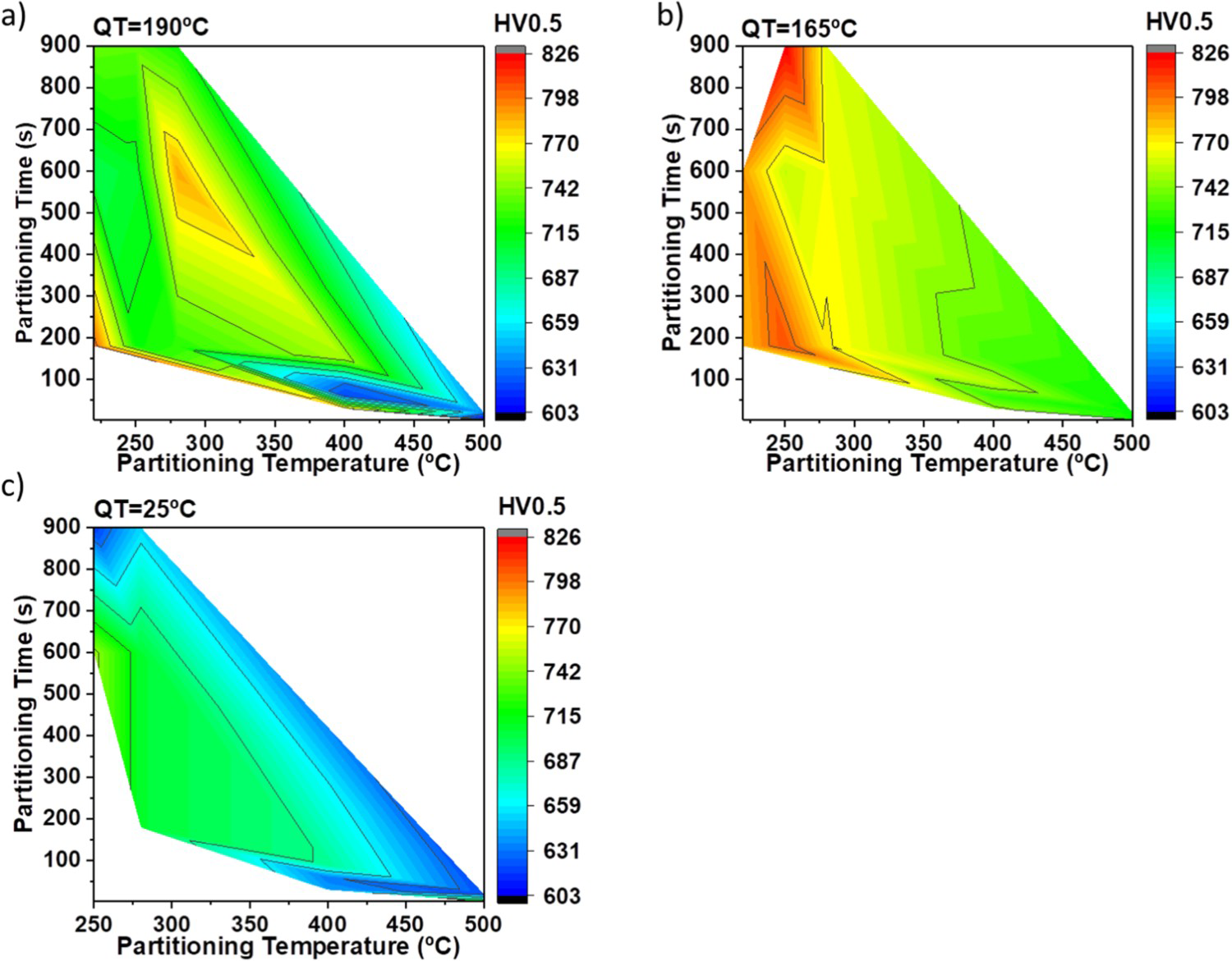
Impact test
Results of the energy absorbed in Charpy V-Notch tests are presented in different colour maps according to the quenching temperature as a function of the partitioning time and temperature (Figure 9). Maps illustrate that the range of absorbed energy for QT25 is obviously higher than for the 2 other quenching temperatures and also the variation between the numbers is low for QT25. For example, the absorbed energy of QT165 could be as high as 10 J for high-temperature PTs while in lower PTs it is less than 3 J, while the changes of QT25 are around 2 J for all the partitioning conditions with PT higher than 280°C.
Colour maps of the impact toughness (J) for each QT. The change in energy absorbed is denoted by alterations in colours as a function of the partitioning time (s) and partitioning temperature (°C).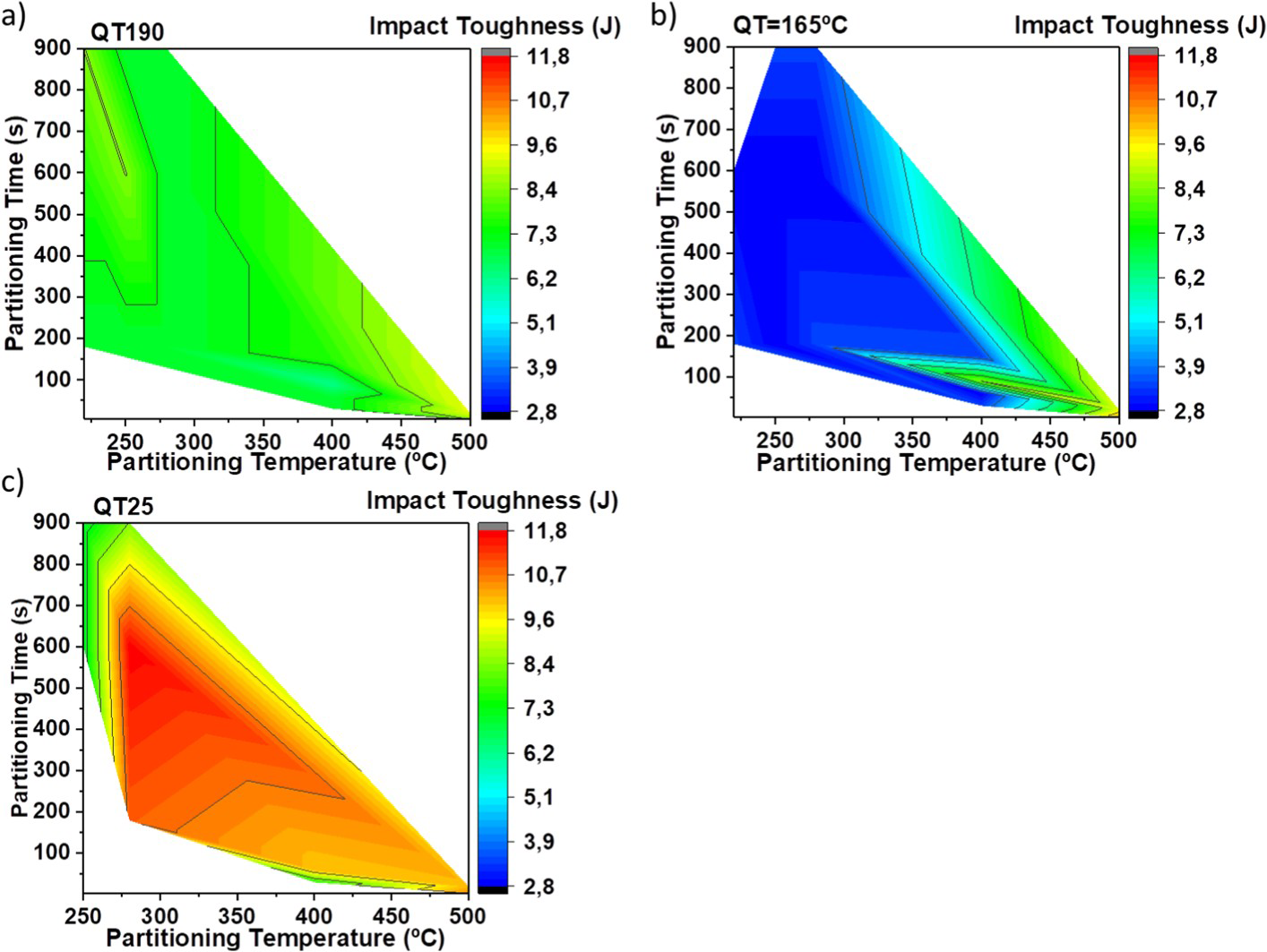
Tensile test
The tensile strength and elongation to fracture for the 11 selected Q&P conditions and one normal Q&T sample (QT25-PT280-Pt2h: quenched to RT and tempered at 280°C for 2 h) are shown in Figure 10. Samples quenched to room temperature achieve not only the highest tensile strength but also the largest elongation to fracture. Since no necking is observed in these samples, the maximum engineering tensile stress is almost the same as the fracture stress. The values of ultimate tensile strength (UTS) rise from 1.1–1.8 GPa for QT165 and QT190 samples and for the QT25 samples values up to 2.4–2.5 GPa are achieved. In addition, elongation to fracture increases up to 4.8–5.7% for these samples. This is mainly because there is no brittle fresh martensite, much finer structure of martensite lathes and a very small fraction of bulky retained austenite in QT25 samples. In addition, these samples show better properties in comparison with the Q&T sample, caused by the higher amount of retained austenite. The reason of such low strength and brittleness of samples quenched at higher temperatures (QT165 and 190) goes back to the high notch-sensitivity of high-carbon fresh martensite, since all these samples had cleavage faceted fracture surfaces in tensile testing.
Results of elongation at fracture vs tensile strength achieved for the different Q&P conditions.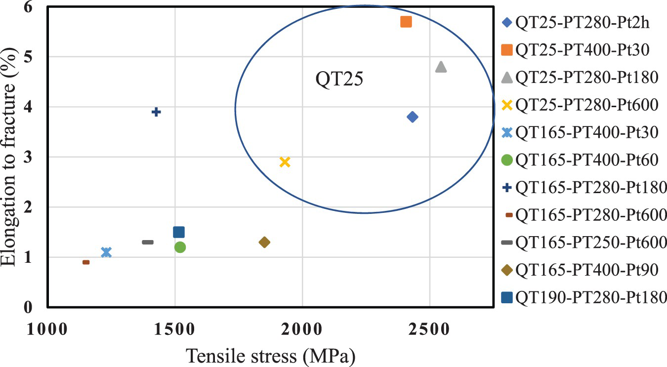
Discussion
In order to find the most accurate data for phase fractions in different samples, all results; image analysis of optical microscopy pictures; Rietveld simulation of XRD data and; EBSD have been compared.
The effect of partitioning duration on the final amount of retained austenite is shown in Figure 11. Results identified by using XRD method show that an increase in the partitioning time at a ‘high partitioning temperature’ (500°C) gives a significant austenite reduction by decomposition of austenite (Figure 11(a)). In contrast, prolonging the time at ‘low partitioning temperatures’ ( Effect of partitioning time on the final amount of retained austenite (a) At high partitioning temperatures (500°C) (b) At low partitioning temperatures (<280°C). Analysis via XRD. 280°C) leads to an increase in the quantity of retained austenite (Figure 11(b)). There are 2 different possible explanation for this phenomenon. Depending on the chemical composition, transitional carbide precipitates can be formed instantly after quenching in martensite before the partitioning stage. Nevertheless, as the formation of cementite is supposed to be inhibited, an increase in the partitioning time may lead to a resolution of these transitional carbides providing, a ‘new’ source of carbon to enrich the austenite carbon content during partitioning [53]. Another explanation about this behaviour is due to the difference between the carbon content of RA achieved after a short partitioning time and the longer time. Retained austenite after a short time partitioning at low temperature has low carbon content resulting in lower stability. By prolonging the holding time at low temperature, the carbon content of austenite increases so that less austenite will transform to martensite during final quenching to room temperature.
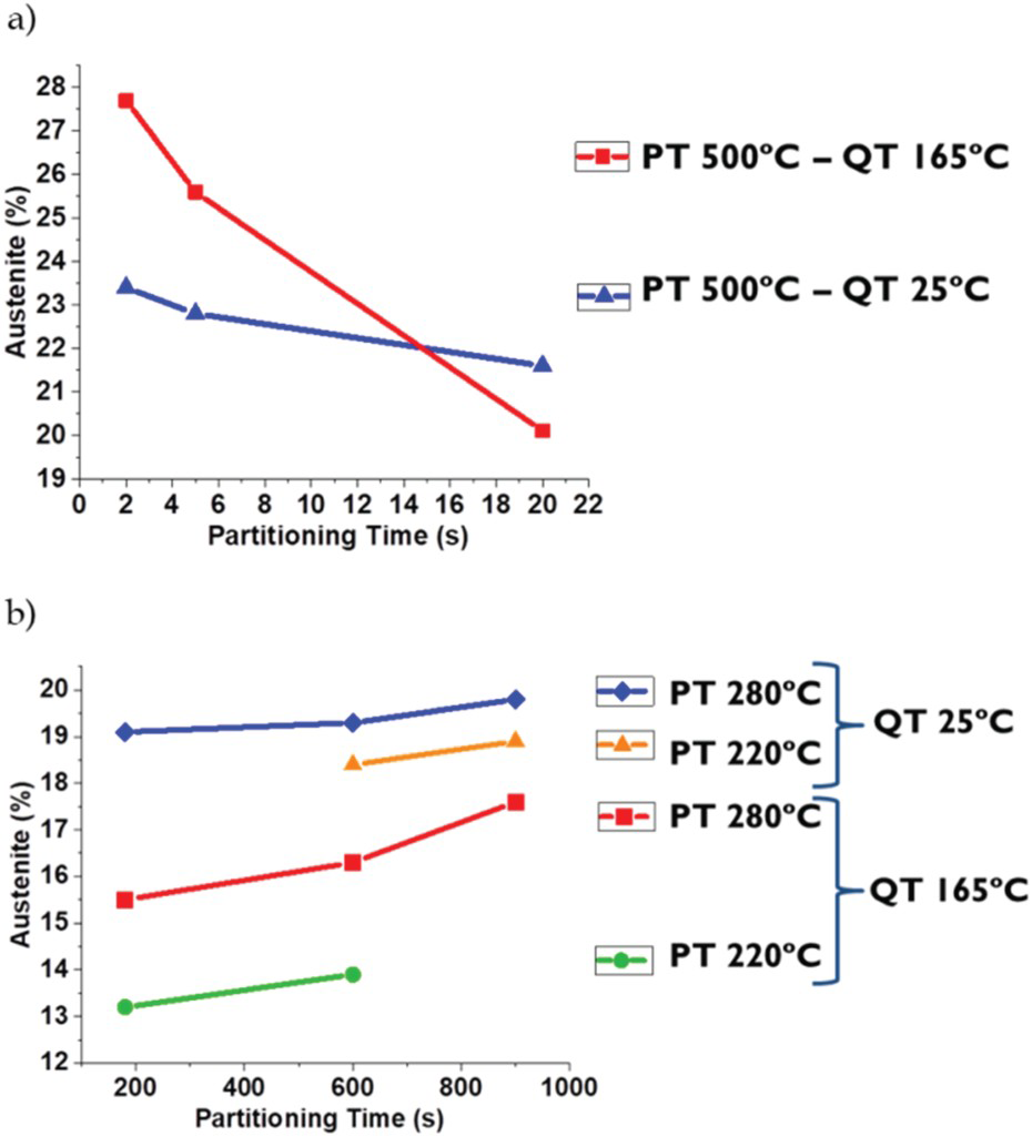
However, the minimum amount of achieved RA at high temperature (20%) is still higher than the highest amount of RA at low temperature. So, the rate of carbon diffusion out of martensite and enrichment of RA is calculated and correlated to partitioning time and temperature in Figure 12.
Diffusion distance of a carbon atom for the partitioning conditions analysed.
Since the rate of carbon diffusion out of martensite is much higher than the diffusion of carbon inside austenite, what will control the carbon diffusion rate and subsequent stabilisation of RA is mainly the rate of carbon diffusion in austenite [54]. An estimation of the distance (r) that a carbon atom can diffuse at a certain temperature and a given time (t) can be evaluated through Equation (1) [55]:
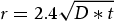
 ) and the temperature in Kelvin, respectively.
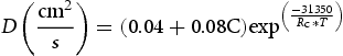
Figure 12 describes the distance diffused by carbon atoms (r) for the partitioning conditions considered in this study. As can be seen in Equation (2), the diffusivity of carbon has an exponential relation with temperature. Subsequently, even though the time is a few seconds at high partitioning temperature, the carbon diffusion is at least two orders of magnitude higher.
Therefore, high partitioning temperatures lead to faster carbon depletion in martensite and, not only a larger amount of carbon is available to partition into austenite but also there is a faster carbon enrichment and carbon content homogenisation of the austenite. Consequently, due to the lower quantity of carbon atoms distorting the martensite unit cell and higher stability of austenite, high partitioning temperatures results in a lower hardness and higher amount of retained austenite. So, it is a question of seconds to control the partitioning time at higher temperatures to control the final microstructure and properties, because after this critical time an increment in time just leads to austenite consumption due to competing transformations (perlite/ferrite, upper bainite, and carbide precipitations).
Comparing the general effect of the partitioning conditions on microstructure and properties of samples quenched at the same QT in Figures 7–9, it can be observed that the partitioning conditions which lead to the lowest levels of hardness are almost the same as for highest levels of impact toughness and retained austenite.
Furthermore, the reduction of austenite amount is faster for higher quenching temperatures (Figure 11(a)), because the amount of initial martensite after quenching is not high enough to stabilise all available retained austenite after the first quench. In other words, a lower amount of carbon is available to stabilise austenite during partitioning and larger pools of austenite will remain for distribution of this carbon. The last two factors decrease the stability of the austenite and are the main reason for the faster reduction of austenite amount at higher quenching temperatures. So, if the carbon content of a RA pool is not high enough, it will transform to fresh martensite during final cooling, which is detrimental, and if carbon content is high enough to stabilise this bulky austenite after quench, it has a higher probability to transform to martensite during deformation [8,26,56]. Chen et al. [57] showed that it is possible to have 2 different carbon contents in RA in the microstructure, high carbon and low carbon bulky RA. Similarly, the higher carbon diffusivity explains the increase in austenite fraction when the partitioning temperature is increased from 220°C up to 280°C.
On the other hand, poor impact toughness of high-carbon steels is mainly caused by large pools of blocky austenite and brittle martensite, since blocky austenite may easily transform to martensite under deformation, when its size is large and the tendency of the martensite to crack also increases with its size. Therefore, the size of austenite blocks should be reduced below the size of phases that can initiate a fracture, i.e. non-metallic inclusions [58].
Conclusions
Formation of different types of martensite after the first quench in Q&P treatment has been compared and the effect of partitioning parameters have been described by analysing the results of hardness, impact toughness, and XRD measurements. These results are reported in several colour maps in order to assist in designing of heat treatments based on desired properties. The best heat treatment in order to achieve the highest hardness, tensile strength and elongation results from the quenching to room temperature (which implies over 80% of initial martensite) and partitioning at high temperatures (500, 400 or 280°C for a few seconds up to a few minutes). Although quenching to 25°C result in lower amount of retained austenite, very small amount of bulky austenite or coarse martensite (detrimental microconstituents) have been observed with this quenching temperature in comparison with QT190 or 165°C. The tensile strength of 2.4 GPa and 5.7% elongation, with around 20% RA and hardness above 730 Vickers was obtained by quenching to 25°C and partitioning at 400°C for 30 s, while other heat treatment conditions lead to a lower ductility but a higher hardness of up to around 800 Vickers. The steels treated by this method costs around 1/50 of maraging steels with similar properties, and the time used in this process is only 1/10th of the best austempering/Q&T treatments resulting in similar properties [13,27].
Footnotes
Acknowledgements
The support of the EUSMAT – European School of Materials via Ph.D. program ‘DOCMASE’ and supports and useful discussions with Dr. Flavio Soldera and Johannes Webel at FUWE, UDS is gratefully acknowledged by the authors.
Disclosure statement
No potential conflict of interest was reported by the authors.
Data availability
The raw/processed data required to reproduce these findings cannot be shared at this time as the data also forms part of an ongoing study. But it could be available upon request.