
Abstract
A simple thermal immersion test with constant heating rate is shown to be an effective method for investigating hydrogen uptake from the decomposing lubricant. It is proven that the black oxide coating can be used as a barrier to hydrogen uptake. Detailed microstructure and composition characterisation of the black oxide layer were also performed.
Introduction
A black oxide coating is a common term used in the engineering industry to produce a magnetite (Fe O
O ) layer on the surface of a component via conversion coating. It has been used in various commercial applications for over 80 years to improve the surface appearance, provide a good base for oil penetration that increases the corrosion resistance [1], increase tool life and most recently it has been reported to improve the reliability of bearings in wind turbine gearbox [2–5].
The black oxide layer is produced when a component is immersed in an alkaline salt solution
1
at temperatures between 130 and 150 C [6–11]. The coating process, however, involves many immersion steps that include surface cleaning, product preheat, black oxide coating, water rinsing, drying and sealant application [7,12–14].
Owing to the nature of the conversion process, one of the key features of black oxide coating, in contrast to other applied coatings and plating processes, is that the oxygen is chemically reacts with the steel and the oxide forms an integrated part with the substrate [15]. Another key benefit of the black oxide coating is that there is virtually no dimensional change of the coating on a workpiece surface. A typical thickness of the black oxide layer is about one to two micrometers 2 [3,10,13].
An adherent black oxide coating on a bearing is reported to improve the reliability and performance of bearings, especially in wind turbines [3,16] and hence reduced downtime and maintenance costs. The benefits of the black oxide coating reported included the enhancement of resistance to smearing and slippage, reduction of fretting, mircropitting, cracking and corrosion, reduction of traction coefficient during run-in and reduction of a chemical attack from aggressive oil additives [2,4,17–19].
However, all of the above works do not address the ability of black oxide coating in stoping hydrogen uptake from the lubricant 3 and hence the prevention of white etching crack (WEC) formation [28–33]. In this work, a thermal immersion experiment coupled with thermal desorption analysis(TDA) is devised to prove that the black oxide coating can be used to prevent hydrogen uptake from unsuitable or contaminate lubricant. This work also includes detailed chemical composition and microstructure characterisation of the black oxide layer, which is comparatively less published studies [4] than the engineering performance of the black oxide coating.
Experimental method
Material of the investigation
A common bearing steel of AISI 52100 type is used as a material of the investigation. The measured chemical composition is 0.96C, 0.29Si, 0.28Mn, 1.36Cr, 0.18Ni, 0.05Mo, 0.152Cu, 0.033Al, 0.0008Ti, 0.00041O in wt-%. The steel was supplied in the spheroidised annealed condition and was machined into  mm coupons before being hardened to a martensitic condition. The details of the hardening process can be referred to Beswick [34]. The microstructure of the hardened sample is composed of residual cementite, tempered martensite, tempered carbide and retained austenite [35]. The hardened samples were surface ground by grinding stone to yield a surface roughness,
  of 0.2 m m before black oxidising. The black oxide conversion coating was performed by Brünofix, Germany, following black oxide coating standard DIN 50938 [7].
Thermal immersion experiment
The effectiveness of the black oxide coating on preventing hydrogen uptake was investigated by a series of constant temperature and constant heating rate thermal immersion experiments. Experiments were first performed on non-coated samples, with the aim of finding the optimum experimental conditions that are the most effective in promoting hydrogen uptake into the steel. The optimum experimental condition was then repeated with black oxide coated samples. A single experiment involved the immersion of two steel coupons in a glass bottle containing a lubricant. The glass bottle was then placed in an oven and gradually heated up to follow a specific thermal cycle, i.e. at a constant temperature or at a constant heating rate (see Figure 1). The temperature of the oven was controlled by Eurotherm PID Temperature Controllers. Air extractor arm was placed near the oven to extract fumes generated. A K-type thermocouple was used to monitor the temperature of the lubricant. The glass bottle was removed from the oven when the time or the peak temperature is reached. Test coupons were taken out from the glass bottle in the fume cupboard, cleaned and stored in liquid nitrogen with minimum delay at the end of each experiment. In this work, the lubricant volume to the specimen surface area is calculated to be 16.6 and 8.3 mL cm−2 for one and two coupons immersion, respectively.
Schematic diagram of the experimental set-up for both the constant temperature and the constant heating rate experiment is shown where the bottle containing the lubricant and steel specimens was placed in an oven with PID temperature controllers. A maximum of four bottles of lubricants can be placed in the oven.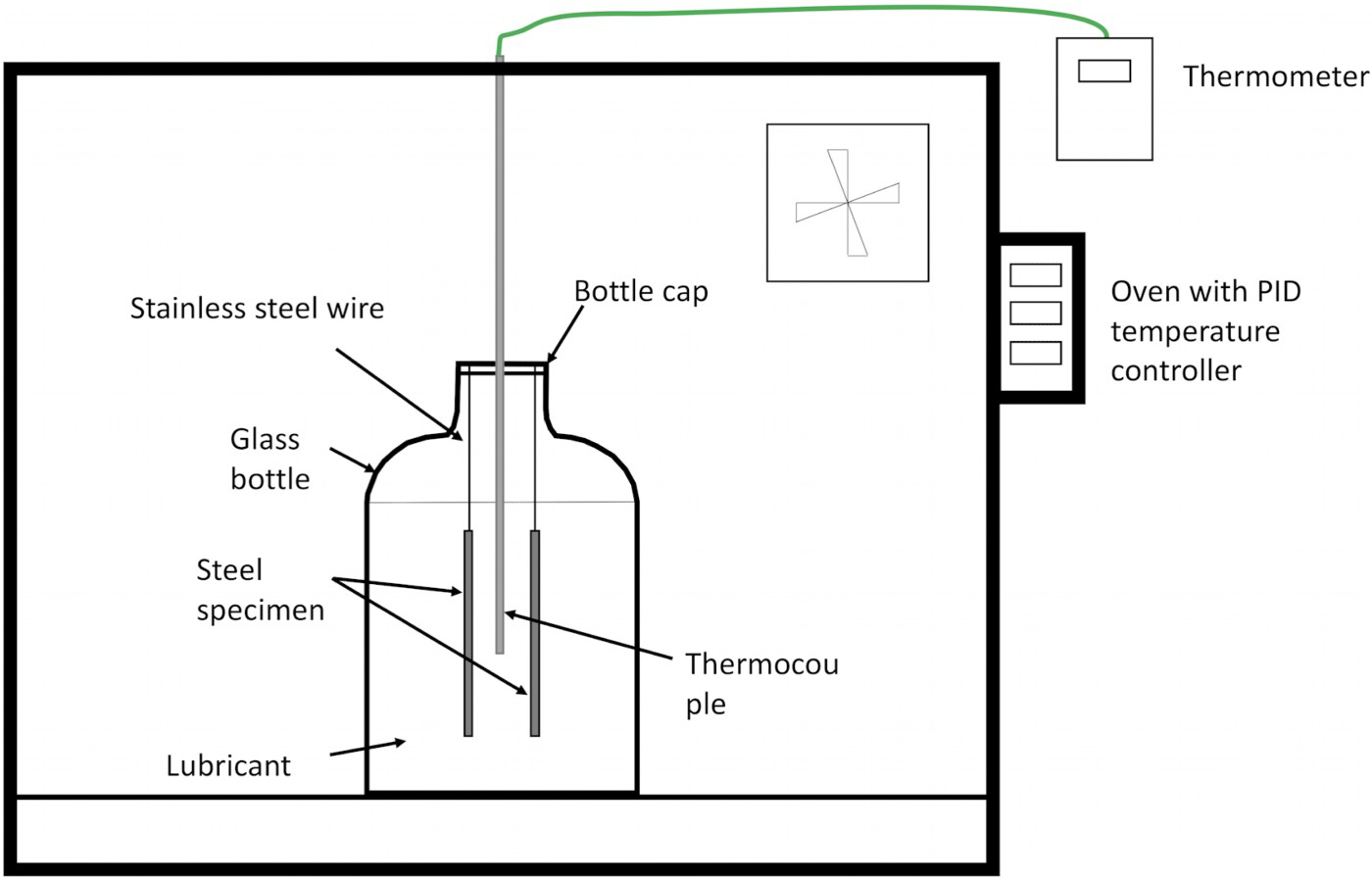
Thermal immersion at constant temperature
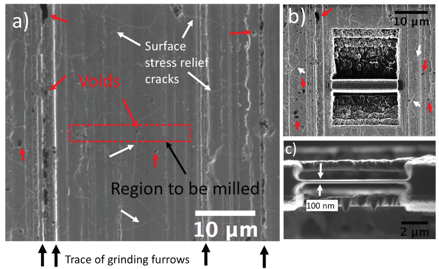
Measured flash point of lubricants used in this work.
 C)
C)Note: The flash point of each lubricant was determine by Pensky–Martens closed cup flash point tester.
The thermal cycle used during the constant temperature immersion are at 60 C for 164 days, 60
 C for 164 days plus 149
 C for 7 h (One steel coupon was taken out from each bottle after 60
 C for 164 days and the leftover steel coupon would undergo an extra heat cycle of 149
 C for 7 h), 149
 C for 39 h and 149
 C for 100 h.
Thermal immersion at constant heating rate
As can be seen later in the section ‘Thermal immersion experiment’, long-term constant temperature immersion in a lubricant did not introduce a significant amount of hydrogen into the steel. This exploratory study couples with the work in SKF [38] that shows the amount of hydrogen generated from boiling lubricant is reduced with increase boiling time and implies that the hydrogen generation from the lubricant is more temperature dependent with less sensitivity to time. Therefore, the immersion of the sample at a constant temperature may first experience high hydrogen uptake, but the hydrogen that was introduced into the steel would desorb out with prolonged immersion time since the hydrogen concentration at the surface is reduced. Furthermore, the discolouration observed on the steel surface after the immersion test also suggests the possibility of a reaction layer that may have prevented the hydrogen uptake at a constant temperature.
For the above reasons, the thermal immersion test was repeated using lubricant Total Transmission TI 75W-80 but with various constant heating rates. The aim is to find out the optimum heating rate that can maintain a high hydrogen concentration at the surface of the testpieces and induced a high amount of hydrogen uptake. The heating rate chosen for this investigative experiment is 10, 20, 50, 100 C h−1. The peak heating temperature during thermal immersion test chosen for this lubricant is 200
 C.
4
C.
4
Thermal desorption analysis
The hydrogen content in the steel samples was measured using a TDA system equipped with a gas chromatograph. VICI Valco pulsed discharge detector (HID/PID HP7890) is used to detect an ultra-low hydrogen concentration. The system was calibrated with a standard gas mixture of He with 60.7 ppm of H . The sampling time was in 3 min intervals. The constant heating rate used for hydrogen desorption is between 25
  C and 100
 C h−1. The diffusible hydrogen content, H
 was calculated from the area under the curve from the evolved hydrogen spectra from the first peak, and the trapped hydrogen, H
 was defined as the area under the curve of the evolved hydrogen content obtained from the second peak. The total hydrogen content reported in this work is the summation of both diffusion and trapped hydrogen and is obtained at below 300
 C.
C.
Hydrogen concentrations in the steel coupons at various stage of processing were investigated. This includes (1) no coating, (2) black oxide coated, (3) after removal of the coating and (4) immersed in a lubricant with or without black oxide coating. Depending on the experimental objective, the hydrogen content in the specimens was measured immediately after the immersion experiment or stored in liquid nitrogen dewar. Storing the hydrogen-charged sample in liquid nitrogen is essential to prevent the hydrogen introduced into the steel from desorbing at room temperature [39]. Before TDA, for steel coupon that was stored in liquid nitrogen, the sample was first washed with water to bring the temperature up from −196 C. Depending on the experimental requirement, surface discolouration (or corrosion products) and black oxide layer were removed by P400-grit size silicon carbide paper. All samples were rinsed with ethanol followed by isopropanol. The compressed air dried coupon was weight before being inserted into the quartz tube for TDA. The sample surface cleaning preparation for TDA typically took less than 5 min. Fast helium gas purging with flow rate more than 100 mL min−1 is used for 20 min before the sample is being heated up. The mass flow control rate of 10 mL min−1 is used during the thermal desorption experiment.
Microstructural characterisation
The black oxide layer was examined in both surface and cross-section. The surface morphology of the oxide was observed in FEI Helios FEG scanning electron microscopy (SEM). Particle size distribution of the oxide was characterised using Digital Instruments Multimode atomic force microscopy (AFM) in contact mode. In AFM, a sharp tip mounted on a cantilever is moved across the sample surface, and the deflections of the tip as it moves are monitored and translated to produce a 3D image of the surface. The sample for SEM and AFM investigation was clean with acetone and ethanol. Cross-section of the black oxide layer with substrate was examined in FEI Tecnai Osiris transmission electron microscope (TEM) operating at 200 kV. The chemical composition and the crystal structure of the oxide layer and its related region were investigated using energy dispersive X-ray spectroscopy (EDS) and selected area diffraction pattern technique. FEI Helios FEG focused ion beam (FIB) is used to prepare the thin lamellar of the black oxide cross-section. Cutting/thinning was performed with sputtering action of Ga ion. A platinum strip was deposited on the surface of a predefined region to protect the oxide scale from being milled away by the ion beam. The lamellar is thinned down to 100 nm thick with reducing Ga ion current to achieve electron transparency. On the final thinning step, 100 pA of Ga ion beam is used to minimise damage to the prepared lamellar. Phase identification of the oxide coating was performed on Bruker D8 Davinci with position sensitive detector (LynxEye EX) using nickel-filtered Cu radiation (K Å). The diffraction patterns were obtained in the 2θ range of 30–70
 with a step size of 0.02.
Materials without immersion
Figure 2 shows the hydrogen thermal desorption rate obtained from the steel at various stage of the production. No diffusible hydrogen is detected in non-coated condition with the total detected hydrogen of 0.015 ppmw. The black oxide coating process introduces small ( Detected hydrogen desorption rate at various stage of the production process. As-tempered sample and black oxide coated sample with or without coating removed during TDA were investigated. The thermal cycle used to desorb hydrogen from the steel sample during TDA is as followed: the heating rate of 50 ppmw),
5
but detectable hydrogen content. With black oxide layer removed during TDA, both diffusible and trapped hydrogen were detected.
ppmw),
5
but detectable hydrogen content. With black oxide layer removed during TDA, both diffusible and trapped hydrogen were detected.
 C h−1 and dwell at 290
 C for 6 h.
The figure also shows that the presence of black oxide layer delays the start of hydrogen desorption to a higher temperature. Furthermore, hydrogen desorption is not complete even after holding at 290 C for 6 h. Figure 2(b) shows that the hydrogen desorption rate decreases at about 700 min but this is due to the decreasing temperature. This result indicates that the black oxide coating process induced small amount of hydrogen uptake with the current sample dimension and the black oxide layer prevent hydrogen desorption.
A small amount of hydrogen has been detected in the steel that has been black oxide coated. This is in contradictory to the report that no hydrogen evolution is expected during black oxide coating due to the alkaline nature of the solution used and no hydrogen embrittlement is expected from black oxide coating [40]. However, the black oxide coating is a surface conversion process. The amount of hydrogen generated is surface area dependence. If the surface to volume ratio of the component is small, the amount of hydrogen introduced into the steel relative to the volume (or weight) will be small due to the dilution effect. The sample dimension used in this experiment is in different shape compared to the one used in reference [40] and in the actual bearing, it follows that the surface to volume ratio must play a significant part in determining the diffusible hydrogen that can introduce into the steel during black oxide coating. The measured total hydrogen due to black oxide coating in the steel coupon is  ppmw with the surface to volume ratio (SA:V) of 2.13 mm−1. For a real bearing product (SKF NCF 2326 ECJB inner ring is used for an example calculation), the SA:V is about 0.1 mm−1. This implies that the total hydrogen increases due to black oxide coating would be less than 0.007 ppmw. Such amount of hydrogen is well below the detectability level of any commercial hydrogen detection system. This approximation indicates that no hydrogen damage or hydrogen embrittlement on the bearing product due to black oxide coating is expected.
Thermal immersion experiment
Diffusible hydrogen promotes WEC formation and premature bearing failure. There is evidence on the absorption of atomic hydrogen into bearing steels from the decomposition of lubricant, additives, or contaminants such as water [36,37,41–46]. In this work, the investigation of hydrogen absorption is performed on a simple thermal immersion experiment. The decomposition of lubricant can be either catalytic or non-catalytic. The presence of catalysts such as in the actual rolling contact test due to the generation of a new metal surface during rolling contact [45,47] can only reduce the maximum temperature of the thermal decomposition of lubricant, but would not change the transformation path. In short, if the lubricant is not stable and is generating hydrogen during decomposition, the hydrogen will be produced with or without a catalyst.
Thermal immersion at constant temperature
Figure 3 shows the change in appearance and colour of the lubricant after undergone two different thermal cycles. The colour of both lubricant B and D become darker while no observable change is observed for lubricant A and C.
The change of appearance and colour of the lubricants before and after undergone two different thermal cycles. Image (c) is taken when the temperature of the lubricant is at about 145 C.
C.
Figure 4 shows that no significant hydrogen absorption (below 0.02 ppmw) into the non-coated steel after thermal immersion in various lubricants at a constant temperature of 60 Detected total amount of hydrogen from the non-coated steels after immersion in various lubricants at a constant temperature in comparison to the steel coupon that was not immersion in lubricant. The thermal cycle used to desorb hydrogen from the steel sample during TDA is as followed: the heating rate of 100 C for 164 days (5.46 months). Further increase the immersion temperature to 149
 C for 7 h did not increase the hydrogen uptake significantly. In fact, hydrogen adsorption in both PAO/ester with ZnDDP and Total Transmission TI 75W-80 oil is reduced. The hydrogen uptake, when immersed in base oil PAO, is the highest and increases with increased immersion temperature, but the detected hydrogen content is still too low( below 0.04 ppmw) and can not be expected to affect the mechanical properties of the steel.
 C h−1 and dwell at 290
 C for 12 h.
As can be seen in Figure 5, immersion of black oxide coated sample in PAO/ester at 149 Total hydrogen detected after thermal immersion experiment on non-coated and black oxide coated sample, with and without black oxide layer removed before TDA. Note: Conditions 1, 3 and 4 are not immersed in lubricant A. The thermal cycle used to desorb hydrogen from the steel sample during TDA is as followed: the heating rate of 100 C for 100 h did not increase the hydrogen content of the steel. In fact, the hydrogen that was introduced during black oxide coating process is desorped out from the steel during thermal immersion experiment.
 C h−1, holding for 6 h.
Figure 6 shows the thermal desorption spectra for black oxide coated samples that were thermally immersed in PAO/ester, with or without black oxide layer removed during TDA. The thermal desorption spectra of black oxide coated sample without thermal immersion with the coating removed before TDA was included in the figure for comparison. A significant amount of hydrogen was detected if the oxide layer is not removed during TDA after thermal immersion in PAO/ester. Minimum hydrogen is detected after thermal immersion if the oxide layer is removed before TDA. With the oxide layer removed during TDA, the hydrogen detected in black oxide coated sample without thermal immersion is more than the one that experiences thermal immersion.
The thermal desorption spectra for black oxide coated samples that were thermal immersed in PAO/ester at 149 C for 100 h, with or without black oxide layer removed during TDA. The thermal desorption spectra of black oxide coated sample without thermal immersion were included in the figure for comparison. The thermal cycle used to desorb hydrogen from the steel sample during TDA is as followed: the heating rate of 100
 C h−1, holding for 6 h.
The high amount of hydrogen is detected from black oxide layer after thermal immersion as seen in both Figures 5 and 6. It is only possible with the PAO/ester reaction with the black oxide layer. However, there is no report on such reaction in the literature.
There are several reasons that may result in low hydrogen uptake during constant temperature immersion. For example, (1) the formation of reaction surface layer may have prevented hydrogen uptake and reduce the hydrogen with increasing holding time at a constant temperature. (2) The temperature used during thermal immersion is not high enough to initiate decomposition of lubricant.
Thermal immersion at constant heating rate
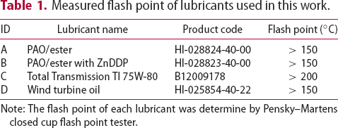
Figure 7 displays the change in surface appearance for steel samples that were immersed in Transmission oil – Total Transmission TI 75W-80 and were heated up to 200 Effect of heating rate on the shade of steel samples after thermal immersion in Transmission oil – Total Transmission TI 75W-80. C with various constant heating rates. No shade or discolouration was observed when the heating rate of 100
 C h−1 is used. However, at a low heating rate of less than 50
 C h−1, the shade of the coupons was darker with reduced reflection. It is clear that there must be a lubricant and steel reaction to produce such discolouration layer.
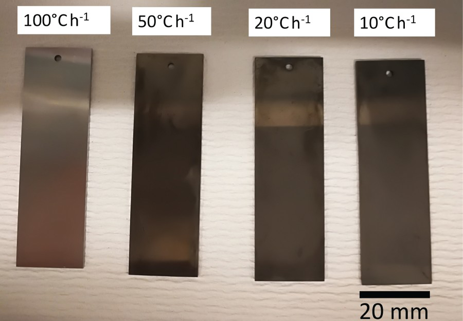
Figure 8 compares the amount of hydrogen uptake after thermal immersion with various constant heating rates. For a non-coated sample, the heating rate of 20 Effect of the black oxide coating on hydrogen uptake in martensitic harden bearing steel. (a) Diffusible hydrogen, (b) trapped hydrogen and (c) total hydrogen. Steel samples were immersed in Transmission oil – Total Transmission TI 75W-80 heat up to 200 C h−1 during thermal immersion induced the most hydrogen uptake. Faster or slower heating rate produced less hydrogen uptake. Heating rates of both 10 and 20
 C h−1 induced the most trapped hydrogen. Indicating that the amount of hydrogen generates from both heating rates may have filled up all the trapping sites.
 C with various constant heating rates. Black oxide layer removed before TDA. The thermal cycle used to desorb hydrogen from the steel sample during TDA is as followed: the heating rate of 25
 C h−1.
It is found that a heating rate of 20 C h−1 induces the highest amount of total hydrogen in the non-coated sample (Figure 8). Thermal immersion of the black oxide coated sample in the lubricant with a constant heating rate of 20
 C h−1 reduces the hydrogen amount that was introduced during black oxide coating. The results indicate that hydrogen uptake from decomposing lubricant is prevented by the black oxide layer.
The equilibrium between the hydrogen generated from the decomposing lubricant and the hydrogen uptake into the specimens will also depend on the thickness of the reaction layer that forms during thermal immersion. The fast heating rate would generate a lot of ‘free’ atomic hydrogen that can be absorbed into the steel, but the short experiment duration prevents significant hydrogen uptake; this is why the detected amount of hydrogen is small. While the slower heating rate of 50 C h−1 would encourage more hydrogen uptake, the heating rate is not optimum. The slower heating rate will provide prolonged duration of hydrogen uptake, but the decomposition of lubricant will also create a reaction layer that prevents hydrogen uptake, which is thought to contribute to the lower hydrogen concentrations when the heating rate of 10
 C h−1 is used. These two competing phenomena will govern the amount of hydrogen that is generated and absorbed into the steel. It was previously shown that corrosion products formed on immersing specimens in a solution of ammonium thiocyanate strongly affect hydrogen absorption [48].
Figure 9 shows the hydrogen evolution rates for both black oxide coated and non-coated samples after thermal immersion in Transmission oil – Total Transmission TI 75W-80 with a heating rate of 20 Effect of the black oxide coating on hydrogen desorption after immersion experiment with the heating rate of 20 C h−1. Both diffusible and trapped hydrogen have been detected for non-coated samples. The peak temperature of diffusible hydrogen is measured at 79
 C and for trapped hydrogen, the temperature peaks at 218
 C. For black oxide coated sample, the trapped hydrogen peaks at 225
 C.
C.
 C h−1. Black oxide layer removed before TDA. The thermal cycle used to desorb hydrogen from the steel sample during TDA is as followed: the heating rate of 25
 C h−1.
Magnetite and other iron oxides are ionic and crystalline, so a very low hydrogen diffusion coefficients can be expected in them. There are many indirect data that show the iron oxide reduces the hydrogen permeability and at a certain thickness, it would act as a barrier to hydrogen diffusion [3,20–27]. Nevertheless, this experiment result shows more direct proof that black oxide coating can be used to prevent hydrogen uptake from the decomposing lubricant. Couple with the result from the previous section, we can now confirm that the black oxide layer is a barrier to both the outward and inward diffusion of hydrogen.
While constant heating rate during thermal immersion test in this work is used mainly to evaluate the effectiveness of black oxide layer in hydrogen uptake prevention from both unsuitable or contaminate lubricant, it can also be used to assess the stability of the lubricant and its ability to induce hydrogen uptake. This experimental set-up is expected to be more time and cost-effective than the tribological type tests such as ball-on-disc and rolling four ball test [31,45,49,50]. Furthermore, hydrogen detection during the tribological test is indirect. The hydrogen measurement during such test is from the vacuum and not from the tested bearings [45,50].
Black oxide coating characterisation
Figure 10(a) presents a top surface view of the black oxide and the region to be milled by FIB. Grinding furrows were observed on the oxide surface. This observation indicates that the surface roughness of the black oxide coating is dependent on the initial roughness of the substrate. Voids and surface stress relief cracks were also seen on the surface. The void formation is thought to be the nature of the oxide conversion [51]. Surface stress relief cracks are developed because the oxide layer hasa different thermal expansion coefficient compared to the steel underneath [52–54]. When this stress becomes large enough due to the cooling of the oxide layer and the substrate from 130 (a) SEM image of the general features observed on the surface of a black oxide coating. Grinding scratches, as well as voids and surface stress relief cracks, are observed. The region to be extracted via FIB was also labelled. (b) The surface morphology observed on the oxide surface after two trenches was milled by FIB. (c) Prepared TEM lamella ready for TEM characterisation. C to the room temperature, cracks form on the oxide surface to relieve the stress. Small and individual cracks join up to form a connected network that look like grain boundary. However, there is no evidence that the cracks are related to the prior austenite grain boundaries on the steel. As can be seen in Figure 10, void and surface stress relief crack were included in the FIB region, so that it can be investigated via TEM. Figure 10(b) shows the surface morphology of the oxide after trenches were milled by FIB. Figure 10(c) shows the prepared lamella and the thickness of the black oxide surface ready for TEM characterisation.
High-resolution TEM was used to investigate the black oxide layer. Figure 11 shows the cross-section of the black oxide layer prepared by FIB, where the steel substrate, magnetite, void and surface stress relief cracks are labelled. The black oxide layer thickness varied from 1.0 to 1.6 mm.The microstructure reveals a very different oxide structure that produced via high-temperature oxidation [55].
Black oxide layer TEM image of lamellar produced by FIB. The remnant of martensitic microstructure on the magnetite can be seen. The crack on the oxide layer is observed to propagate from the surface into the substrate. The selected areas SA1–SA6, where the diffraction patterns were taken, also labelled on the image.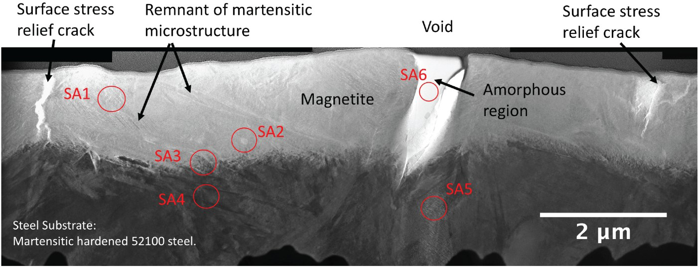
The irregular branched shape cracks observed in the oxide layer are surface stress relief cracks that start from the surface and propagate toward the substrate. The presence of surface stress relief cracks and voids on black oxide does not affect its ability to prevent hydrogen uptake. The reason is that as observed in Figure 11 not all surface cracks propagate through the oxide layer and reach the steel substrate, for the surface stress relief cracks that reached the steel substrate, they must be account for very small area(line) per unit surface.
The observation of the remnant of martensitic microstructure within the oxide layer indicates that the magnetite is transformed directly from the preexisting martensitic structure through the diffusion of oxygen into the solid steel [56,57]. The inward diffusion of oxygen into the steel rather than the outward diffusion of iron for oxide formation is the origin of the excellent adhesion of the black oxide coatings.
Selected area diffraction technique was employed to characterise the crystal structure of the oxide layer and steel substrate. The obtained selected-area diffraction from regions ( SA1–SA3) could be indexed as Fe (a) Diffraction pattern obtained from area SA1 proving the oxide layer is magnetite. Trace of haematite was also detected. (b) Diffraction pattern obtained from area SA2, undissolved residual cementite is observed within magnetite. O
O confirming the oxide layer is crystalline magnetite. Arcs rather than spots were observed on all Fe
 O
O reflections (Figure 12, SA1 region in Figure 11) suggests that the layer is composed of small textured
6
crystallites Fe
reflections (Figure 12, SA1 region in Figure 11) suggests that the layer is composed of small textured
6
crystallites Fe O
O . Since the selected area (see Figure 11 for the actual size) used in this work to obtain the diffraction pattern is smaller than a typical martensite packet size,
7
such an observation is direct proof of inward oxygen diffusion, and the transformation of tempered martensite to oxide is dependent on the crystal orientation of the tempered martensite. As reported by Bhadeshia [58], the oxide layer can be in a mixture of both magnetite (Fe
. Since the selected area (see Figure 11 for the actual size) used in this work to obtain the diffraction pattern is smaller than a typical martensite packet size,
7
such an observation is direct proof of inward oxygen diffusion, and the transformation of tempered martensite to oxide is dependent on the crystal orientation of the tempered martensite. As reported by Bhadeshia [58], the oxide layer can be in a mixture of both magnetite (Fe O
O ) and haematite (Fe
 O
O ), in Figure 12(a), trace of haematite was detected.
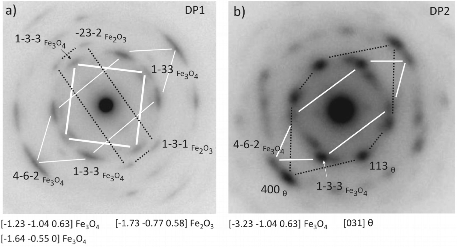
A visible residual cementite is observed within the black oxide layer in region SA2. The diffraction pattern obtained from that region is shown in Figure 12(b). This finding suggested that the oxidation of residual cementite is slower compared to the steel substrate. Both iron carbide and free carbon within the tempered martensite would oxidise to form carbon monoxide and carbon dioxide [59,60]. Since there will be a difference in transformation rate and path for both carbon-rich and carbon deplete region within the tempered martensite, this may be the reason for the observation of the remnant of martensitic microstructure within the oxide layer. It has been known that grain and lath boundary can accommodate more carbon atom than within the lath.
The interface between the oxide layer and the underlying substrate is diffuse across the sample; this is particularly clear at high magnification as shown in Figure 13. The measured diffusion interface width is about 400 nm. Figure 13(b) shows the selected area diffraction from region Figure 13(a), the weaker spots corresponded to the tempered martensite reflections. The diffuse interface between oxide layer and substrate indicates excellent bonding. In fact, black oxide coating does not delaminate and they are simply worn off during rolling contact [61].
(a) Bright field TEM image of the magnetite and steel substrate interface. It is shown that the interphase is diffuse. (b) Selected area electron diffraction pattern corresponding with bright field images from area SA3 showing both magnetite and tempered martensite diffraction spot.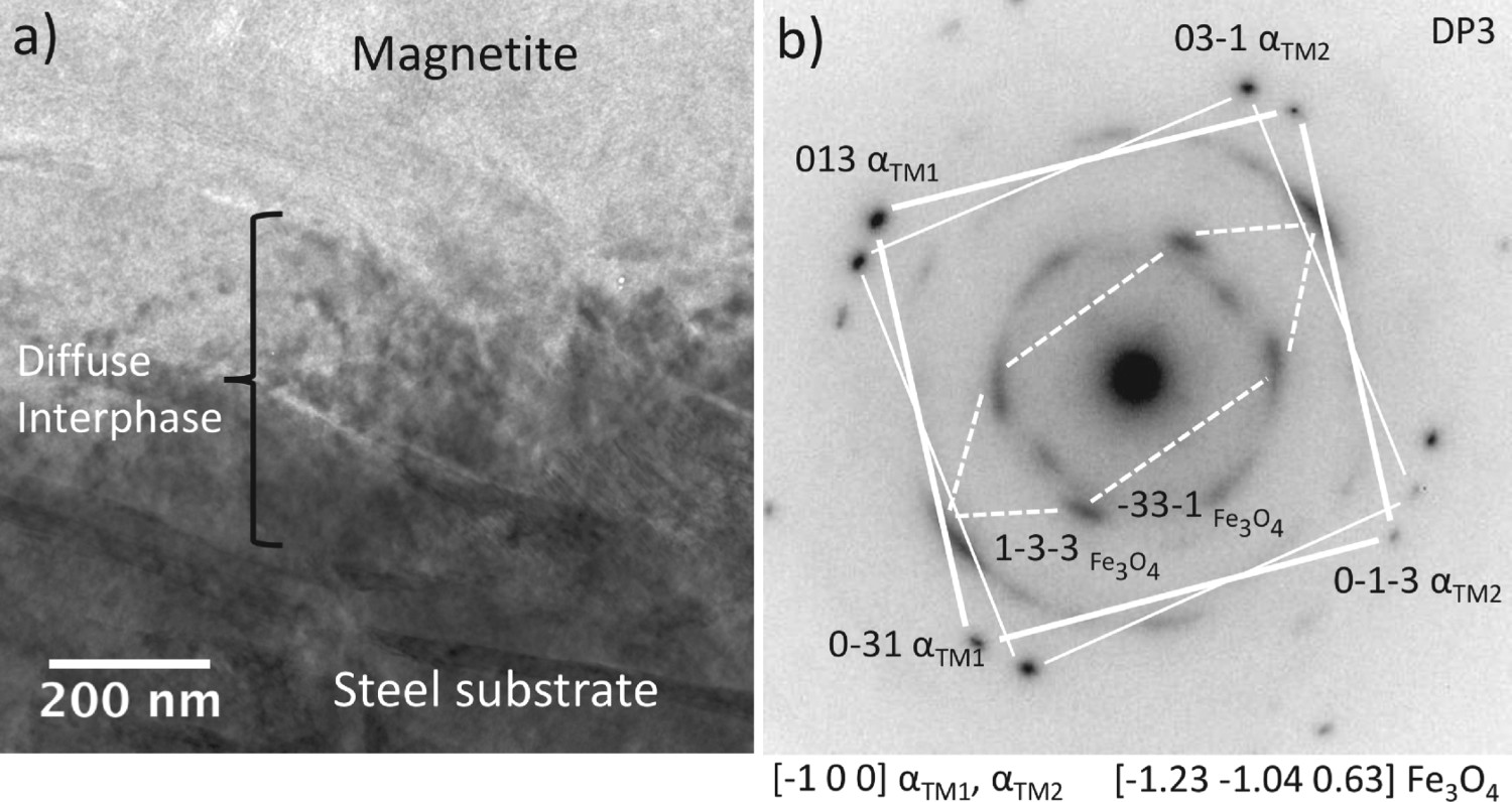
Figure 14 shows the diffraction pattern obtained from area SA4 and SA5 which is situated within the substrate. Figure 14(a) displays the diffraction pattern obtained from tempered martensite and retained austenite and Figure 14(b) shows the diffraction pattern obtained from tempered martensite and tempered cementite precipitates. The obtained microstructure is typical of that produced by in martensitic harden bearing steel proving that the black oxide coating process did not induce any significant microstructure change.
Diffraction patterns obtained from the substrate region. (a) Diffraction pattern obtained from area SA4 showing tempered martensite and retained austenite. (b) Diffraction pattern obtained from area SA5 showing tempered martensite and tempered cementite precipitate.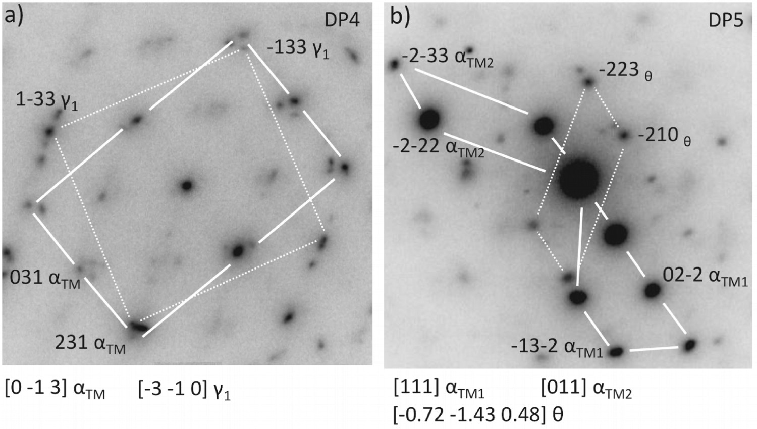
Figure 15 shows the diffraction pattern obtained from region SA6 is amorphous. EDX chemical composition analysis indicates that this region is high in carbon content. Since this is a void region (see Figure 10), it is suspected that the amorphous matter is the residual from the oil used to seal the black oxide coating at the end of the black oxide coating process.
Diffraction pattern obtained from SA6. The diffuse rings indicate an amorphous structure in this area.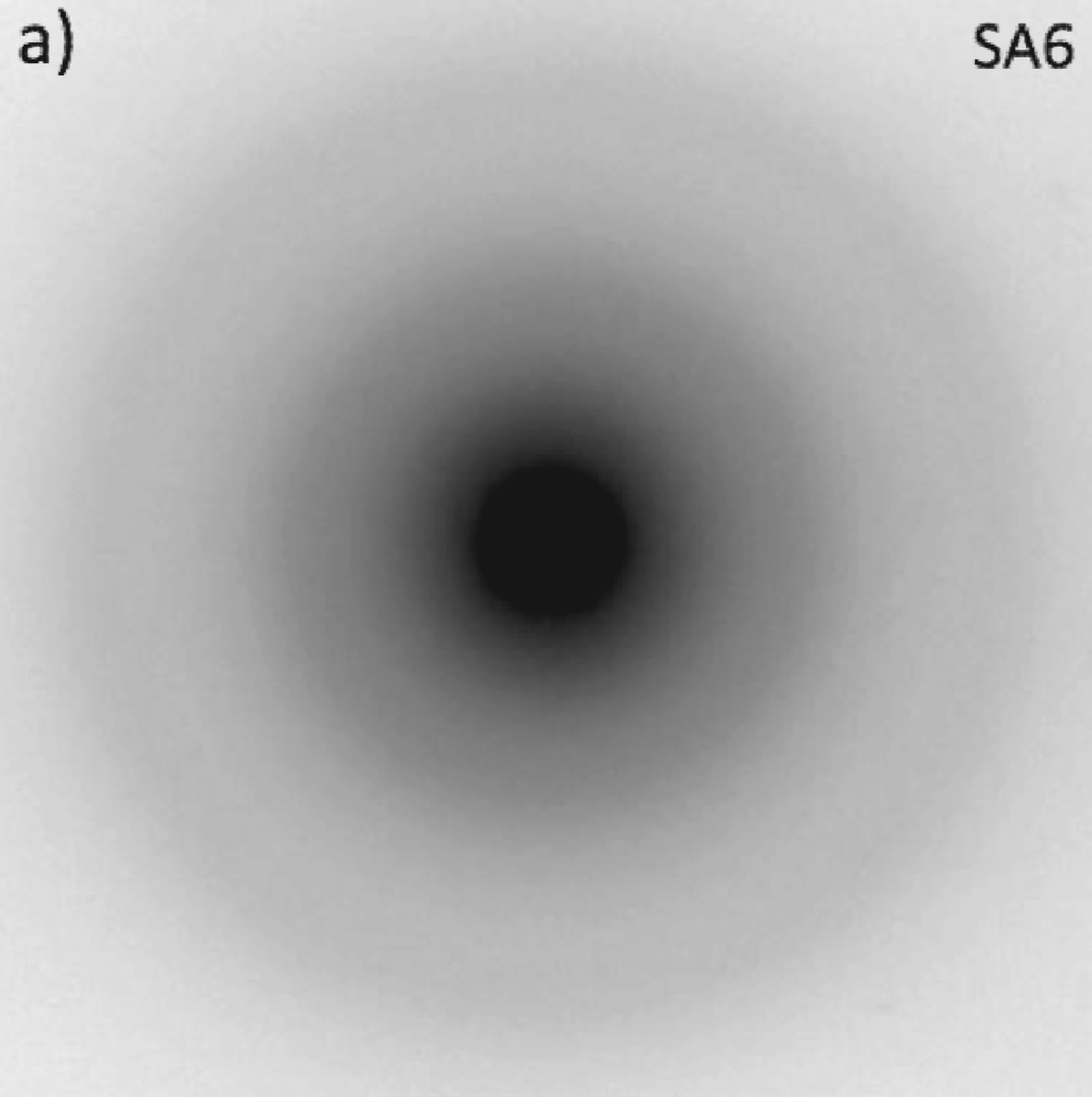
EDX analysis was used to provide chemical information of the region of interest and aid the interpretation of the experimental result obtained from the preceding diffraction pattern analysis. Figure 16 shows a partial area of Figure 11 and a series of positions where qualitative EDX chemical composition measurement was performed.
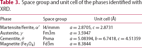
The measured chemical composition of the black oxide layer and substrate. The label position indicates the spot where the chemical composition was measured.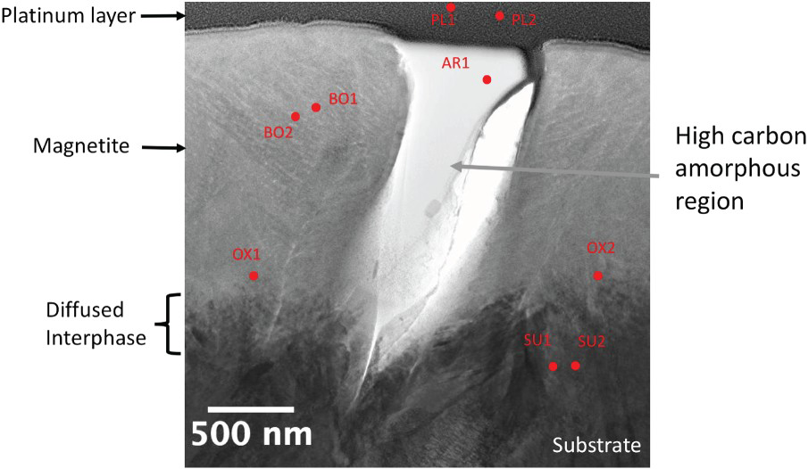
The atomic ratio between iron and oxygen is calculated to be 0.85 and 1.16 within the black oxide region (BO1 and BO2) indicates that the magnetite is nonstoichiometric, which is consistent with the report that magnetite is frequently nonstoichiometric [62].
The chemical composition of the platinum layer, black oxide, amorphous region, oxide and substrate interphase and substrate in wt-%.
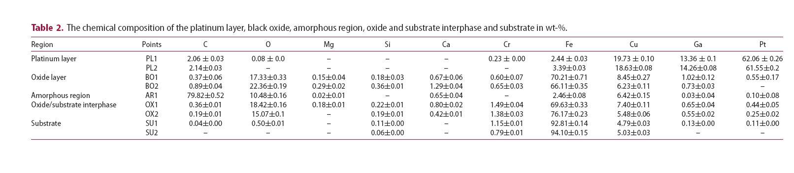
The detection of Pt, Cu and Ga is due to the sample preparation and the sample holder used. Pt is used to protect the sample during FIB sample preparation and for welding the TEM lamella to the holder. The sample holder used for TEM lamella attachment is made of Cu. The detection of Ga is due to Ga ion implantation since Ga ion is used for cutting and thin the sample.
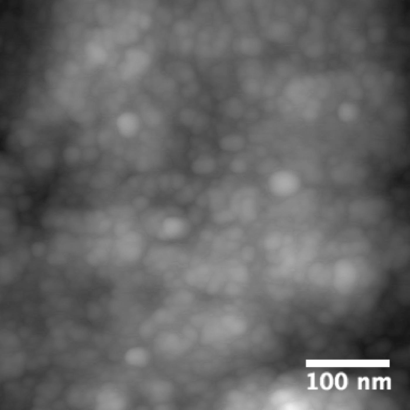
The particle morphology of the black oxide coatings is illustrated by AFM image in Figure 17. The size of magnetite particles is in the order of Particle size on the surface of the oxide. nm. The observed nanosize particle size agrees well with the observation made by Kuznetsov [63] who also performed AFM investigates on the oxide surface. Such a small particle size would also produce a powdery mass as observed by Roberson [64].
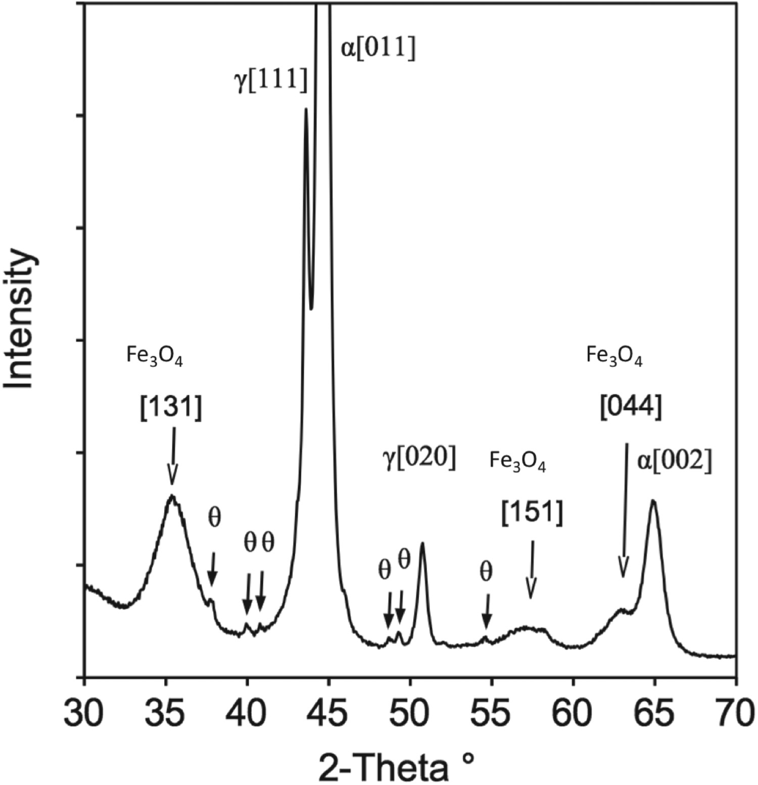
X-ray diffraction pattern of the prepared black oxide coupon is shown in Figure 18. It revealed the presence of four phases, α, γ and θ peaks from the tempered martensite substrate and also black oxide layer of magnetite (Fe X-ray diffraction pattern obtained from the black oxide surface. Space group and unit cell of the phases identified with XRD. O
O ). The phases identified by XRD are listed in Table 3, along with the measured unit cell using the stated space group. The obtained X-ray peak from magnetite is relatively broad which indicated that the crystallite size of the magnetite is relatively small. This observation agrees well with the detection of small particle size in AFM. Both diffuse interface between magnetite and the substrate and a small particle size obtained after black oxide coating is expected to be beneficial for the rolling contact fatigue performance of a bearing.
Conclusions
The main conclusions and new findings from this work are as follows:
The black oxide layer is a barrier to hydrogen uptake from the lubricant. The black oxide layer also impede hydrogen desorption at room temperature and delay hydrogen desorption up to 200 Small concentration of hydrogen uptake during black oxide coating is not expected to cause hydrogen embrittlement in bearings. The observation of the remnant of martensitic microstructure within the oxide layer is the direct proof that the oxide is formed directly from the martensitic structure through the diffusion of oxygen into the solid steel. Thermal immersion test with constant heating rate can be used to evaluate hydrogen embrittlement potential for a particular lubricant.
 C.
C.
Footnotes
Acknowledgments
The authors would like to thank Marc Ingram from Afton Chemical for the provision of lubricants. The authors are grateful to Professor Sir Harry Bhadeshia, Steve Lane, Mohammed Faid and Wijbe Buising for the provision of lubricants, samples, helpful discussion and comments.
Disclosure statement
No potential conflict of interest was reported by the authors.
1
Typically contains varying proportions of a mixture of 60–80% sodium hydroxide, 15–40% sodium or potassium nitrite or nitrate, catalysts, activators and other proprietary additives.
2
The coating thickness is the actual thickness of the oxide layer and this is not the same as a build-up in plating or other surface deposition coating, which can sometimes be assumed as the dimensional difference between the coating layer and the originally component dimension.
3
4
The flash point of the lubricant is >200C and the autoignition temperature of the lubricant is >250C.
5
Owing to the detection sensitivity of the TDA used in this work and the large surface to volume ratio of the sample in this experiment the minute hydrogen was detected. The paragraph in this section would address the effect of black oxide coating process and the effect of large surface to volume ratio of the sample on the hydrogen uptake.
6
All crystals have nearly the same orientation.
7
The orientation within the martensite packet has a similar orientation.
References
 S
S nanoadditized lubricant for applications affected by hydrogen embrittlement
 N
N : II. Residual strains and blisters in the oxide layer
 C) in air and the effect of water vapor
 iron carbide catalyst phases in Fischer–Tropsch synthesis: controlling