
Abstract
A novel steel has been designed for use in the oil and gas industry, displaying properties comparable with the currently available F22 grade and possessing the additional quality of excellent hydrogen trapping capacity. Its high strength is derived from a martensitic microstructure containing a dispersion of fine vanadium-molybdenum carbides that evolve during thermal treatments. If the tempering cycle is controlled such that the precipitates maintain a degree of coherency with the matrix, then they act as hydrogen trapping sites, due to the associated strain fields, thus mitigating the problem of diffusible hydrogen. Using material modelling programmes and small-scale sample alloys this work describes the process of the new steel design and demonstrates its superior trapping capacity through thermal desorption analysis.
Introduction
Extracting resources from deep oil and gas reservoirs can be an attractive prospect that presents significant technical challenges for the industry. Deeper reservoirs require materials that can perform at higher operating temperatures and pressures. Simply increasing steel strength for such sub-sea applications is not appropriate because the accompanying microstructure exacerbates the susceptibility to hydrogen embrittlement [1–4], as do residual stresses caused by welding. Toughness and ductility are invariably sacrificed for strength as different characteristics are balanced, so the real challenge is to improve multiple properties without detriment to others. Additionally, the presence of hydrogen, that arises through cathodic protection [5,6] or the transportation of hot fossil fuels [7,8], is a major concern and its ingress in to the steel can lead to embrittlement [1].
It is, therefore, necessary to create an alloy which is capable of trapping infused hydrogen [9–12] and rendering it harmless [13], one which can be welded and at the same time meet a variety of structural integrity criteria including operating temperature requirements. The alloy/weld system must both be suitable for mass production and implementation. In this work, the metallurgical design is based on secondary-hardening, i.e., an alloy with sufficient hardenability to produce martensite, followed by tempering which induces the precipitation of carbides based on substitutional solutes such as vanadium and molybdenum. A typical heat treatment would involve austenitisation, cooling and then tempering in the range 500–650 C where large atoms are mobile enough to form the alloy carbides [14]. It is noteworthy that the tempering temperature is sufficiently high that it should render the steel stable at even the highest temperatures experienced in a deep sea environment involving the transmission of hot fossil fuels.
There are several reasons why a secondary-hardening system would be the preferred microstructure. Foremost, the strength needed is readily generated. For example, a simple alloy of composition Fe–0.1 C–2Mn–0.4 Mo–0.6V wt-% can, following quenching and tempering, reach a hardness of 400 HV (approximately 1200 MPa UTS) due to the precipitation of Mo and V-rich carbides [15]. Such an alloy would contain fine (Mo,V)C particles, which provide the hardening mechanism while avoiding carbon in solid solution within the matrix. Dissolved carbon in ferrite strengthens but also causes embrittlement [14].
The particles serve an additional vital purpose, if the heat treatment is controlled so that they are small enough to be partially coherent with the matrix, the resulting strain fields can interact with the hydrogen and trap it so that it can no longer do harm [16–18]. An example of this concept is hydrogen penetration into bolts, which is known to cause erratic, static-fracture. In an effort to increase the bolt strength beyond 1000 MPa, it was necessary to develop a new alloy that was not prone to delayed fracture. The commercially available steel contains (Mo,V)C and has shown a large capacity to trap hydrogen [15,19].
Joining steel often presents problems and for many sub-sea applications it is necessary to weld the material, which must be designed to tolerate the consequences of localised heat input. Hard zones created adjacent to the weld are particularly deleterious to the fabrication. This problem can be mitigated by keeping the carbon concentration as low as possible [20].
Alloy design and small experimental melts
Alloying elements and their contributions.
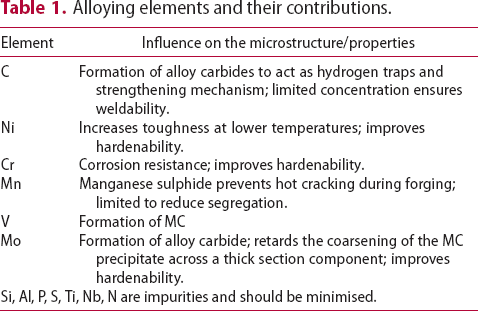
A
2
range of potential alloy combinations was investigated initially using simulations to calculate time–temperature-transformation diagrams [24], mechanical properties [25] and equilibrium phase diagrams (Matcalc) [26]. Finite element analysis (ABAQUS) was also performed to calculate the cooling rate of a typical component during still air cooling conditions.This first stage of the steel design process focused the composition parameters to develop the hardenability, carbide size/stability and the role of unavoidable impurities. From these analyses three compositions (Table 2) were predicted to exhibit the required properties and used to produce small experimental 70 g melts by vacuum-arc melting. The specimens were then homogenised, annealed and swaged into 7 mm rod as shown in Figure 1, in preparation for precipitation hardening. This was achieved by austenitising at 1050 Experimental vacuum-arc melts (a) before and (b) after swaging. Hardness of experimental alloys following austenitisation, cooling and tempering at 600 Measured chemical compositions (wt-%) of the experimental alloys and f22. C for 0.5 h, air cooling at 7200
 C h−1 and then tempering for up to 24 h at 600
 C. Hardness testing provided an indication of the phases present and the expected strength before the commissioning a sizeable quantity of material for full characterisation. Figure 2 shows the hardness result and indicate that HT5 may not achieve the strength requirements after tempering for 2 h. Although HT4 appears likely to achieve the highest strength, with stability over the tempering range, this could be to the detriment of toughness. HT10 was selected as a compromise and was predicted to display the greatest toughness given the nickel addition, which also enhances the hardenability.
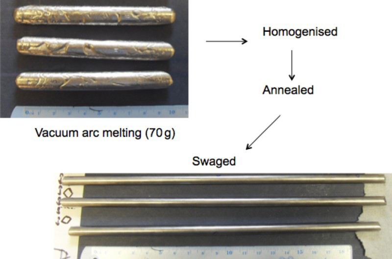
 C. Red dash line at 250 and 300 HV indicate the base and stretch target requirements of the alloy design.
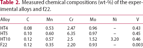
Large experimental melts and experimental procedure
 mm blocks and hot-rolled to 20 mm thick plate, thus providing a forging reduction ratio of 4.5–1. The material was re-heated to 1250
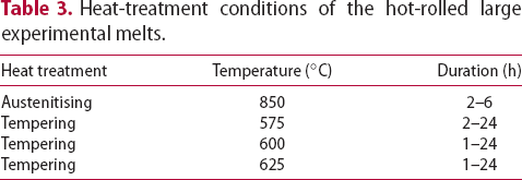
 C for 1 h before rolling which comprised of seven passes. Table 3 shows the heat-treatment conditions performed on the hot-rolled steel for hardness measurement prior a full materials characterisation.
Heat-treatment conditions of the hot-rolled large experimental melts.
 C)
C)Classic metallographic techniques were used to characterise the as-received and heat treated material. A Vickers machine was used for hardness testing. Tensile and Charpy impact specimens were cut from the longitudinal and transverse direction, with respect to the plate rolling direction. The tensile specimens were cylindrical, 4 mm diameter and 20 mm gauge length and the strain rate was 0.002 s−1 at room temperature. Impact tests were carried out at  C using standard Charpy V-notched specimens.
Transmission electron microscopy (TEM) was used to characterise the microstructure and identify any carbides generated during tempering. TEM specimens were prepared as electro-polished foils and the microscope used was an FEI TECNAI Osiris operating at 200 kV. The chemical composition of the precipitates was determined by Energy Dispersive Spectroscopy (EDS).
Thermal desorption analysis (TDA) was used to measure the hydrogen trapping capacity of HT10 and benchmarked against the F22 grade steel. Test coupons ( mm) were ground to 400 SiC grit and electrochemically charged with the hydrogen for 2–48 h in an aqueous solution of 3.5 % NaCl at 0.5 mA cm−2. No discoloration of the surface was observed during this process and charging was performed at ambient temperature. Before TDA, the specimens were kept at 22
 C for 1–14 days until the readily diffusible hydrogen had evacuated
3
,leaving only the trapped hydrogen. This room temperature aging duration is dependent on the heat treatment.
C for 1–14 days until the readily diffusible hydrogen had evacuated
3
,leaving only the trapped hydrogen. This room temperature aging duration is dependent on the heat treatment.
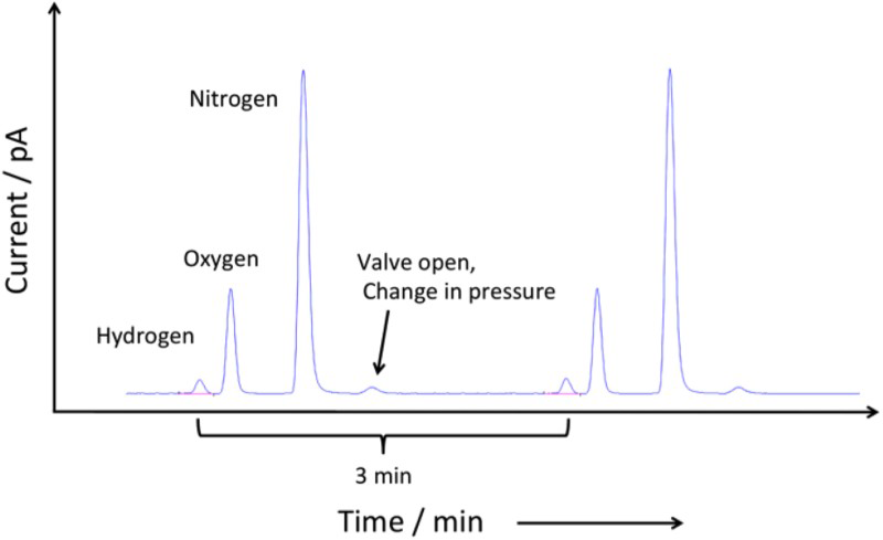
The trapped hydrogen that is forced to evolve during heating was measured by heating the charged (and room temperature aged) coupon at a constant rate of 100 Thermal desorption system. Chromatogram obtained during thermal desorption. C h−1 in a resistance tube furnace as shown in Figure 3, using a helium carrier gas set at a flow rate of 10 ml min−1. The hydrogen desorbed from the specimen (along with air) is carried by the helium and injected into the gas chromatograph column at 3 min intervals where it is separated and then detected with a pulsed discharge ionisation detector. A typical chromatogram shows the hydrogen peak first, followed by oxygen and nitrogen is presented in Figure 4. The hydrogen desorption rate was defined as the amount of hydrogen evolved in 1 min per gramme of the specimen. A standard gas mixture of He + 60.7 volume ppm of H
 was used for the calibration.
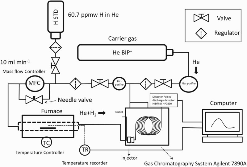
The hydrogen desorbing rate  is calculated for a carrier gas flow rate (f) of
  as follows:
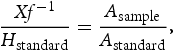
 is the hydrogen standard used for calibration with a known concentration in one mole of helium;
  and
and  are the areas under the TDA curves for the sample and standard respectively, in units of pA min.
Microstructure
The HT10 alloy displays a high degree of hardenability, producing martensite for a range of cooling rates. The microstructure in Figure 5 is air-cooled (7200 HT10 tempered martensite microstructure following austenitisation at Fine V–Mo–Cr-rich carbides observed in sample tempered at 600 MC precipitate observed after tempering at 600 Large V–Mo–Cr-rich carbides observed after austenitisation at 850 Chemical composition of the precipitate and matrix identified in Figure 6. C h−1) and tempered at 600
 C for 10 h. Observations under the TEM, show precipitates within the martensite laths and also at the lath boundaries. These fine platelet precipitates are less than 20 nm in length and 5 nm in thickness, as observed in both Figures 6 and 7. They appear to be heterogeneously distributed within the martensite lath and composition mapping indicates that they are V–Mo–Cr-rich. The chemical concentrations at the points identified (Figure 6) and the measured Mo/V ratio of the precipitate are presented in Table 4. The indexed FFT diffractogram (Figure 7(b)) of the high-resolution transmission electron microscope image in Figure 7(a) identified that the precipitate is of MC or M
 C
C type with the crystal structure of face-centred cubic(FCC). Precipitation can occur following austenitisation at low temperature (850
 C), as shown in Figure 8, however, these alloy carbides are much larger (>70 nm) and spherical in nature compared with the fine plates formed during tempering.
  C for 0.5 h, air cooling and tempering at
  C for 10 h.
 C for 10 h. Black and white arrows point the carbides at different orientation indicating the shape of the carbide is platelet.
 C for 10 h; (a) HRTEM image (b) FFT diffractogram of (a) showing that the alloy carbide possesses Baker and Nutting orientation relationships with martensite lath.
 C and fast cooling.
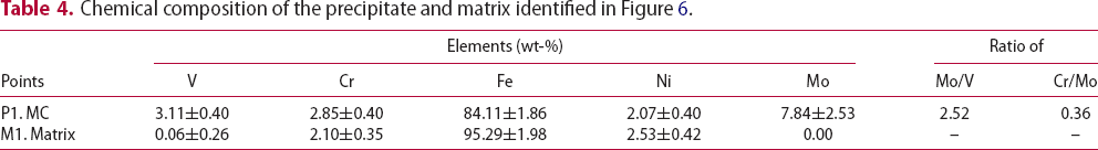
Mechanical properties
The heat treatment that HT10 alloy is subjected to has a significant effect on its properties, especially during the austenitisation and tempering cycle. Figure 9 highlights the influence of austenitisation duration versus tempering time on hardness, this value can be multiplied by a factor of three to approximate the tensile strength [27]. The temperature of the austenitisation temperature determines the amount of the carbon in solution before quenching, which affect the martensite strength and free carbon for MC carbide formation. Clearly, the tempering time determines the final properties and as the fine carbide precipitates begin to coarsen along with a reduction in dislocation density, the material loses its strength. Figure 9 indicates that HT10 can be austenitised at 850 The influence of austenitisation duration at 850 C for a range of times without affecting the hardness significantly. This is a necessary material property because a thick section forging may take several hours to achieve a homogeneous temperature during austenitisation.
  C and tempering (600
 C) time versus hardness.
Additionally, the tempering temperature can be used to control and alter the mechanical properties considerably, Figure 10. Lowering the tempering temperature increases the time required to obtain a designated/target hardness, which could be considered time-consuming. However, this would allow greater control during the heat treatment in order to produce uniform properties across the through thickness, especially when slow heating rates are necessary. The influence of tempering temperature versus hardness after austenitisation at 850 C. Data for temper at 600
 C and 625
 C were obtained from different hot-rolled plates.
Through manipulation of the thermal treatment, it is possible to produce a wide range of strength and toughness values as in both Figure 11 and Table 5. Table 5 provides details of the thermal treatment, together with the measured mechanical properties of the heat treated alloy obtained in each case. The results are compared with F22 grade steel [22]; for an equivalent impact toughness, HT10 displays a much higher strength and for the same impact toughness. The relationship between Charpy impact toughness and tensile strength for HT10; F22 values are included from the literature [22]. Effect of solution treatment temperature and time as well as the tempering temperature and time, following water quenched on measured mechanical properties. Note: YS: 0.2% Proof strength (MPa); UTS: Tensile strength (MPa); El: Total Elongation (%); CVN: Charpy impact toughness energy measured at 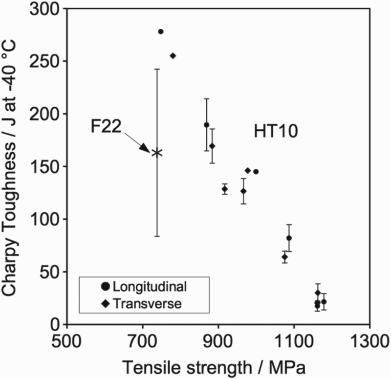
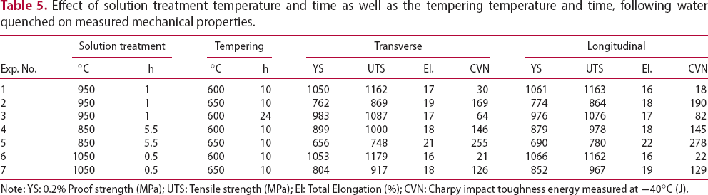
 C (J).
 C
C C
CThermal desorption analysis
Thermal desorption spectra of trapped hydrogen in HT10 steel are presented in Figure 12 for specimens solution treated at 850 The effect of tempering conditions and electrochemical charging time on thermal desorption spectra of trapped hydrogen in HT10 steel. Thermal desorption data; (a) total trapped hydrogen, (b) peak hydrogen evolution temperature. C for 5.5 h tempered at 600
 C and 625
 C for 1, 10 and 24 h. As expected, charging for 48 h introduces more hydrogen into the steel for most tempering conditions. The total quantity of trapped hydrogen shown in Figure 13 is obtained by integrating the area under the hydrogen evolution rate curves (Figure 12). For each experiment, the trapped hydrogen concentration peaks with a tempering time of 1 h at a temperature of 600
 C. This observation can be explained by the coherency strain fields surrounding the alloy carbides. During the early stages of precipitation, the fine particles are coherent with the matrix but as they coarsen with increasing time, they lose coherency [15].
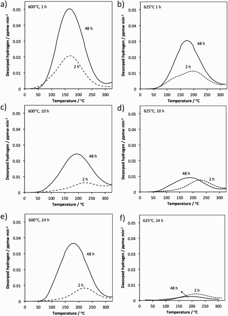
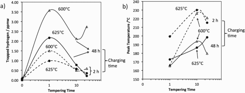
Figure 13(a) indicates that extended hydrogen charging times are required to achieve saturation as the hydrogen trapping capacity increases. The small difference in trapped hydrogen for the 2 and 48 h charging experiments for the sample that has been tempered at 625 C for 10 and 24 h suggests that most of the hydrogen is trapped during partial charging. The results also imply that traps with higher binding energies may be filled first, this is because higher peak temperatures are observed for the 2 h charging times, Figure 13(b). A longer tempering time leads to relatively coarser precipitates, reducing the effectiveness of the traps, thus leading to a lower peak temperature. This is also the case for the data from 625
 C experiments. Small amount of hydrogen is still trapped in the steel that experienced long tempering time indicates that not all precipitates lost their coherency after tempering for 24 h.
The trapping capacity of HT10 was compared with a high strength variant of F22 grade steel (UTS∼925 MPa), which was austenitised at 920 Thermal desorption spectra of HT10 and F22. C for 1 h, quenched and then tempered at 580
 C for 4.5 h. All specimens were charged for 48 h and the spectra (Figure 14) confirms that HT10 has an enhanced ability to trap hydrogen. Both steels were heat treated to approximately the same tensile strength but HT10, with its designed microstructure, displays a significantly greater trap-site density.
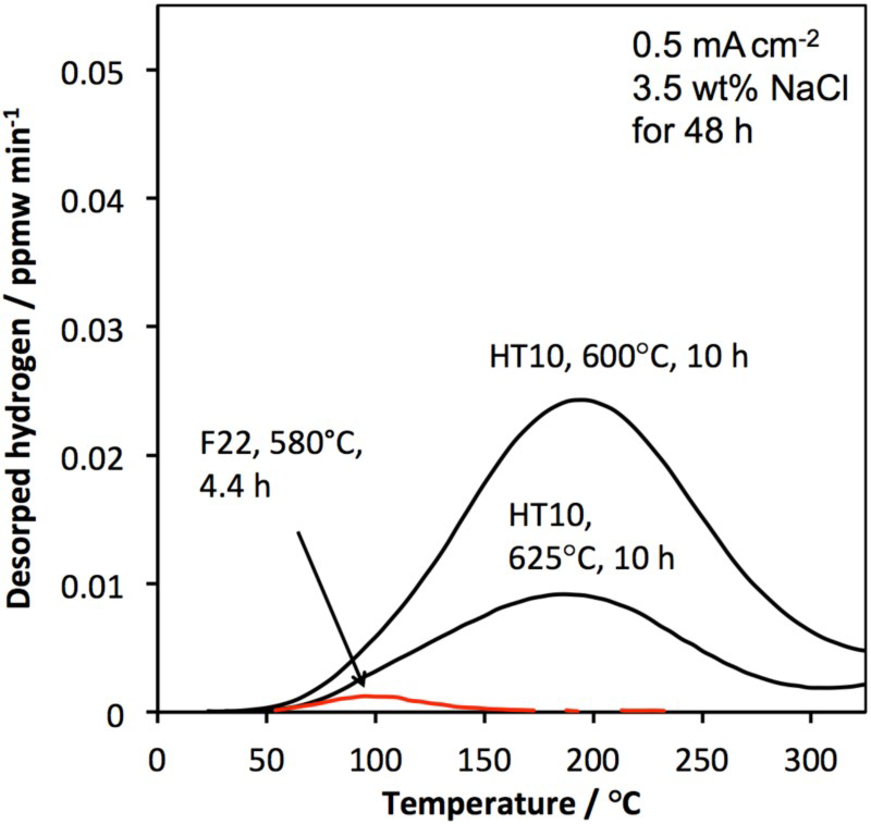
A longer tempering time leads to relatively coarser precipitates, reducing the effectiveness of the traps, thus leading to a lower peak temperature. This is also the case for the data from 625 C experiments. This has now been stated in the text.
Conclusions
A low alloy, quenched and tempered martensitic steel, HT10, has been designed for sub-sea applications in the oil and gas industry and compared with the commercially available F22 grade. From this study, the following conclusion and recommendations have been drawn:
HT10 is able to manifest a range of mechanical properties depending on the thermal treatment, where the tempering time and temperature display the most significant influence. HT10 can be manufactured with a higher strength, without compromising impact toughness, when compared with F22 steel. HT10 has a significantly greater capacity to trap hydrogen than F22 steel. The properties of HT10 are controlled by the microstructure, this is a dispersion of fine plate-shaped V–Mo–Cr-rich carbides in a martensitic matrix that contribute to both strengthening and hydrogen trapping.
Footnotes
Disclosure statement
No potential conflict of interest was reported by the authors.
1
F22 steel is a low alloy steel containing nominally 2.25 wt-% chromium and 1 wt-% molybdenum.
2
Vanadium rich carbide with face-centred cubic structure, the exact chemical composition of this carbide is not known and may vary with bulk chemical composition and heat treatment. Most commonly reported as M and M. ‘M’ represents metal atoms which include titanium, niobium, vanadium and molybdenum.
3
The same TDA system is used without heating to ensure no hydrogen is detected at the start of the TDA.
References
 C
C precipitates on the hydrogen induced mechanical degradation in Fe-C-V alloys