
Abstract
The high-cycle fatigue (HCF) properties of γ-TiAl (gamma titanium aluminide) alloys are reviewed, particularly with regards to the deformation mechanisms active in the near-threshold cyclic loading regime. By examining the influence of lamellar orientation and thickness on the HCF threshold, in addition to more conventional microstructural considerations such as the grain size or the volume fraction of lamellar colonies, factors to improve the γ-TiAl microstructure for HCF are assessed. Finally, experimental methods and loading strategies are surveyed to identify techniques for improving HCF testing of γ-TiAl alloys. In this, we consider both the conservativism of differing approaches and the possibility to measure with suitable resolution the local mechanical behaviour under HCF of the lamellar γ-TiAl microstructure.
This review was submitted as part of the 2018 Materials Literature Review Prize of the Institute of Materials, Minerals and Mining run by the Editorial Board of MST. Sponsorship of the prize by TWI Ltd is gratefully acknowledged.
Keywords
Introduction
Gamma titanium aluminide (γ-TiAl) alloys are emerging as a viable lightweight replacement to nickel superalloys, for use in both the turbine and compressor stages of aero-engines [1,2], as well as in high performance automobiles [3] and the nuclear industry [4]. By mid-2017, the γ-TiAl alloy Ti–48Al–2Cr–2Nb (at.-%) has seen 6 years of commercial flight aboard the GEnx engines (General Electric, U.S.A.) [1]. Pratt & Whittney, with MTU, is also using the third-generation forgeable TNM TiAl alloy in their new geared turbofan engine [1]. For almost three decades, much of the research into these alloys has focused on the low ductility and toughness that limits the tolerance to fatigue crack growth (FCG). This results in a steep slope of the Paris region for FCG when compared to conventional superalloys and steels. In turbines, high-cycle fatigue (HCF), where the number of cycles to failure,  , is greater than
  , is due to aerodynamically induced vibrations at a component's inherent resonant frequencies, as a result of changes in rotational speeds. This HCF therefore exists in addition to the steady state or low-cycle fatigue (LCF –
  ) loading that occurs upon engine start up and shut down. As a result of the low FCG tolerance, the most promising approach to fatigue lifing for HCF in γ-TiAl alloys has been to operate with stress intensity factors below the FCG threshold,
  , commonly at 50%[5] of the maximum peak cyclic loading stress at which the material can endure
  cycles without failure, known as the run-out strength. Below this stress, the FCG rate should be vanishingly small (
 m cycle−1).
For the next generation of titanium aluminide alloys, higher operational stresses and temperatures, to 750 C or higher, would enable a significant number of components in commercial aero-engines to be replaced by γ-TiAl alloys [2,6]. To direct the improvement of γ-TiAl alloys for HCF, a complete understanding of the mechanisms by which microstructures resist crack nucleation and growth is required. Similarly, an increased consideration of the complex HCF loading conditions that the component must withstand is required to optimise the texture of γ-TiAl alloy microstructures this top-to-bottom approach has been reviewed recently [7].
Several reviews of the fatigue properties of γ-TiAl alloys exist [8,9]. However, most of the understanding of FCG is focussed on plasticity in the bulk and at crack tips during LCF; HCF is treated using conventional approaches to fatigue life evaluation [10,11]. The present review aims to assess the potential for less conventional methods and considers progress in the understanding of the HCF behaviour of γ-TiAl alloys since ∼2010. This review begins with a brief overview of conventional HCF characterisation of TiAl alloys in ‘Conventional, Macroscopic Analysis of the HCF Behaviour of γ-TiAl Alloys’ section, in which the effect of loading and test conditions on the HCF behaviour is discussed. Fatigue crack nucleation mechanisms are covered in ‘Fatigue Crack Nucleation Mechanisms in γ-TiAl Alloys’ section. Following this, considerations specific to lamellar γ-TiAl microstructures, such as the orientation of lamellar colonies (i.e. the packets of co-planar  -Ti
-Ti Al and γ-TiAl lamellae that are each formed from a single high temperature disordered α-TiAl grain) to the loading axis and the lamellar thickness, are discussed in ‘Lamellar TiAl-Specific Considerations for Crack Growth in HCF’ section. Finally, the possibility for the application of novel test methods to study the HCF behaviour of γ-TiAl alloys down to thenanometre scale, and with loading procedures that generate deformation fields typical of HCF conditions in industrial applications, will be covered in ‘Outlook for HCF Research on TiAl Alloys’ section.
Conventional, macroscopic analysis of the HCF behaviour of γ-TiAl alloys
Damage-tolerant design
The Paris law of FCG [12] considers the rate of crack growth, Schematic of FCG curves. Adapted and redrawn from [9] (reproduced with permission). Characteristics of the three regimes of FCG, adapted from [10]. , as a function of the applied stress intensity factor,
  , according to
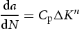
 is a constant, measured crack growth coefficient and n is the dimensionless Paris exponent. On a logarithmic plot (Figure 1), a central, linear section of a sigmoidal FCG dataset exists, beyond the threshold stress intensity
  and before the onset of unstable crack growth at
  . The gradient of the straight line fit to this central region equates to the Paris exponent (Figure 1). The characteristics of the three regions of the Paris curve are shown in Table 1.
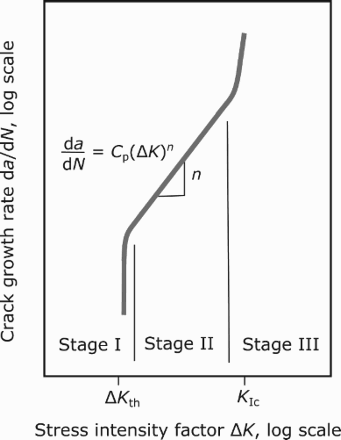
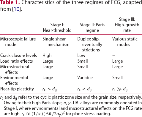
 and
and  refer to the cyclic plastic zone size and the grain size, respectively. Owing to their high Paris slope, n, γ-TiAl alloys are commonly operated in Stage I, where environmental and microstructural effects on the FCG rate are high.
  for plane stress loading.
For many structural materials in the aero industry, a damage-tolerant design is favoured, by which the propagation of cracks occurs but at a sufficiently slow rate for the rate of crack growth to be measured. This requires the slope of the Paris regime of FCG to be sufficiently low (∼3–5) that changes in the stress intensity factor do not cause a rapid increase in crack growth rate.
However, titanium aluminide alloys have a Paris exponent of FCG curves for various TiAl alloy microstructures; all have high gradients in Stage II. From [13] (reproduced with permission). (see Figure 2), depending on the microstructural condition [13]. This was identified early on for second-generation TiAl alloys and complicates their use in the Paris regime, as a 1 MPa m
 increase in the stress intensity range can cause the crack growth rate to rise by a factor of over
  (Figure 2). The reasons for and the effects of such a high Paris slope are often misunderstood. Indeed, though the Paris slope is often equated to that of engineering ceramics [14], the toughness of lamellar γ-TiAl alloys can reach 30 MPa m
 – part-way between the few MPa m
 of ceramics and the ∼200 MPa m
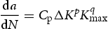
 that high strength steels can achieve. The ductility of γ-TiAl alloys is also greater than that of engineering ceramics, being of the order of 1% strain. To better understand the mechanisms behind crack growth in this intermetallic alloy, one should consider the modified Paris law according to Hojo et al. [15]. It describes the FCG behaviour of both ductile and very brittle materials by accounting for both the effect of the cyclic stress intensity range and the maximum applied stress intensity:
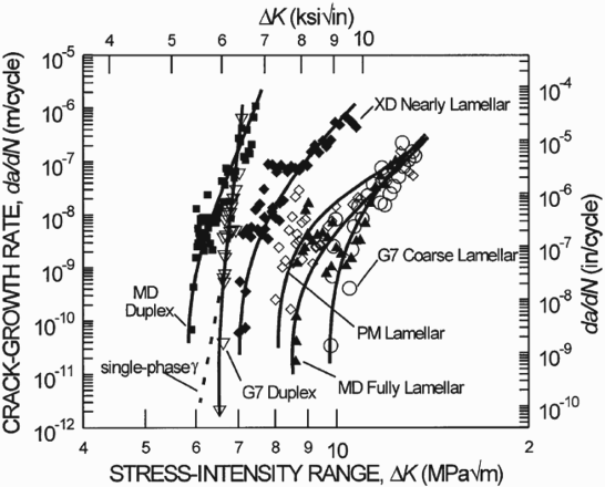
 , whereas for toughened ceramics where some cyclic loading may be achieved,
  , such that the maximum loading stress is the most damaging aspect of fatigue [16]. Intermetallic materials, such as γ-TiAl alloys, lie somewhere in between, with
  , such that values of n=50, obtained by fitting experimental data to the Paris law are gross over-evaluations of the dependence of the FCG rate on the cyclic stress range itself. Filippini et al. [17] demonstrated that neither
  nor
nor  alone can fully describe the FCG properties of Ti–48Al–2Cr–2Nb (at. % henceforth). Similarly, tests at fixed
  on the same alloy by Dahar et al. found the Paris slope n to increase with
  [18], due to static failure modes being activated at higher
  .
.
Recently, there has been renewed interest in the use of TiAl alloys in the Paris regime, driven by the wish to use the material in the higher temperature parts of the aero-engine [2]. This requires the material to withstand temperatures up to 850 C [6] and higher stresses. Hence, an improved understanding of, and potential operation within, the crack growth regime (i.e. Stage II) is essential. FCG data of region II fatigue of Ti–48Al–2Mn–2Nb [19,20] shows that both the crack growth prefactor,
  , and the Paris slope, n, decrease significantly above 750
 C (the latter to n=4), suggesting that once the ductile–brittle transition is exceeded, damage-tolerant design may be achievable if sufficient strength can be maintained. It has been reported that the Paris slope is lower when the lamellae in a TiAl lamellar colony are oriented parallel to the loading axis [21]. Recently, bulk single colony samples have emerged where the orientation of the lamellae can be controlled by the processing method [22], without seeding. This allows components to be produced where the lamellae lie parallel to the loading axis throughout and may result in a further renewed interest in lifing by damage tolerance; this is discussed further in ‘Fatigue of Polysynthetically Twinned Crystals’ section.
Early studies by Gloanec et al. [23] on powder metallurgy (PM) consolidation by hot isostatic pressing (HIPping) of γ-TiAl alloys revealed that the FCG rate in the Paris regime for the Ti–48Al–2Cr–2Nb alloy was approximately two orders of magnitude higher than the equivalent cast material, even after correction for crack closure. This was attributed to the PM processed material possessing a microstructure of fine equiaxed γ grains that was less able to resist FCG compared with the cast, HIPped and heat treated material where coarse lamellar colonies gave rise to a tortuous crack path [23]. Further analysis of this dataset by Zuo et al. [24] identified the effective Paris slope (m in ‘Crack Closure’ section) to be independent of stress ratio and similar between both cast and PM alloys, 8.11 and 8.39 respectively. Rather, it was the  prefactor of Paris regime crack growth that was the processing and microstructure-dependent variable [24] and caused the reduction in fatigue behaviour of the PM material. However, this effect was less marked at higher stress ratios where roughness-induced crack closure effects (see ‘Crack Closure’ section) are less significant.
The development of additive PM processing methods for γ-TiAl alloys has also brought about renewed investigation of fatigue in region II. The application of electron beam melting (EBM) additive manufacturing, a patented advanced PM process [25], to second-generation Ti–48Al–2Cr–2Nb and third-generation Ti–(45–47)Al–8Nb–2Cr (TNB) has enabled near-net shape blade parts to be produced with minimal material wastage compared to cast parts [26]. EBM decreases the porosity and other typical defects compared to casting, and increases the lamellar colony content compared to conventional PM material. This was found to produce superior FCG characteristics, although only the  was higher (∼6 MPa m
 at a stress ratio R=0.05 for EBM and 5 MPa m
 at R=0.1 for PM) and the Paris slopes were similar.
Stress-life approach
The stress-life (S-N) data compiled by Larsen et al. [27] on second-generation γ-TiAl alloys indicates that across a range of microstructures, the maximum run-out strength ( cycles),
  , remains above ∼80% of the ultimate tensile stress,
  . Furthermore, the maximum stress of HCF loading for γ-TiAl alloys can exceed the initial yield stress of the material, irrespective of the stress ratio. This holds even for recent high niobium alloys [28]. Even at target operational temperatures, e.g. 700
 C, the maximum run-out stress is at least 70% of the ultimate tensile strength, as a result of a decreased yield strength and increased ductility, at high temperatures, without any substantial change to the work hardening behaviour. This indicates that some degree of plastic cycling must occur in TiAl alloys cycled at the maximum run-out stress across the temperature range, as they are loaded above the elastic limit. This will be discussed further in ‘Towards a Microscopic Model for HCF Loading of TiAl Alloys: a Focus on Plasticity’ section.
The emergence of gigacycle test methods [29,30] has meant that S-N measurements are no longer limited to Gigacycle fatigue S-N of Ti–45Al–10Nb. Redrawn from [32] (reproduced with permission). cycles;
  is now commonly achievable. Testing of the alloy Ti–45Al–10Nb [31,32] revealed that by
  cycles at a stress ratio of 0.1, an endurance limit was reached, although this is not seen in samples tested at R=0.5 which lasted for
  cycles (Figure 3). Considering the nature of HCF by resonant vibrations in turbine blades which are already experiencing a steady-state centrifugal load, the apparent absence of an endurance limit even by
  cycles at high R is prohibitive to conservative lifing to a stress well below a run-out value.
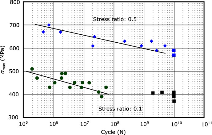
The standard method for determining the FCG characteristics of γ-TiAl alloys has been to test at a frequency of 20 Hz and a stress ratio R=0.1, with progressive load shedding to measure the threshold stress intensity according to ASTM standard E647 [11]. Features of conventional fatigue threshold measurements commonly encountered on γ-TiAl alloys, such as stress ratio dependence and small crack effects, are discussed in the following subsections.
Crack closure
The dependence of the fatigue threshold on the stress ratio, Mechanisms for FCG in intermetallics, compared with those present in metals and ceramics. Extrinsic toughening in intermetallics may be achieved by grains bridging cracks, such as bridging lamellae in lamellar γ-TiAl alloys. In ceramics and intermetallic composites, crack bridging may additionally involve strong and stiff fibres, or elongated metallic grains that undergo ductile rupture [16]. Ahead of the crack in γ-TiAl intermetallics, crack growth may occur by cleavage fracture along fatigue cycled slip planes and by coalescence of microcracks ahead of the crack tip; static fracture modes also occur. Microcrack/microvoid toughening occurs in the proximity of cracks. Adapted from [16] (reproduced with permission). , for γ-TiAl alloys can be accounted for by considering the possibility for crack closure effects, first proposed by Elber [33]. For each stress intensity range
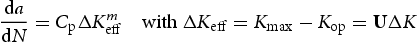
  an effective range
  is considered in the Paris law treatment [10,34]:
 is a material-dependent function that depends mainly on R and
  , and
, and  is the stress intensity factor at which a crack opens fully.
  is the stress intensity at which the crack begins to make closure contact upon unloading and in practice
  [10]; this occurs at a critical stress ratio
  . The dependence of the fatigue crack threshold
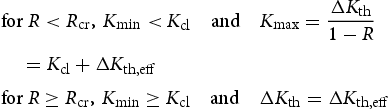
  on R resulting from crack closure can further be accounted for to produce an effective fatigue crack threshold,
  , which is independent of R and a material property [35], according to
 was approximately constant across the
  range of testing in both air and vacuum at room temperature. The environment therefore interacts only weakly with the crack at this temperature and
  is constant. Similar results were obtained on lamellar and duplex structures [37]. The reasons for crack closure can be diverse [10] and are material dependent [16]. The extrinsic and intrinsic processes occurring at a crack tip loaded in fatigue for metals, intermetallics and ceramics are summarised in Figure 4. For γ-TiAl, roughness-induced closure appears to be a key mechanism for lamellar microstructures, where tortuous translamellar crack deflection results in a serrated fracture surface, particularly for larger colony sizes [18]. Roughness-induced crack closure does not occur in lamellar γ-TiAl alloys for stress ratios above ∼0.5, and also in the cases of near-γ and duplex structures where smooth fracture surfaces cause only crack tip plasticity, not roughness, to bring the crack surfaces into contact sooner [36]. If fretting occurs alongside oxidation of the crack surfaces, then an improvement in the near-threshold fatigue properties is found at 800
 C, which are better than those at both 25
 C and 600
 C [38,39].
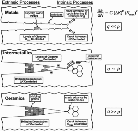
Since the early 1990s, it has been recognised [40] that small cracks ( 1 mm) are of particular concern in the fatigue of γ-TiAl alloys. Indeed, the concept of a threshold stress intensity range
  below which crack growth is vanishingly low (
 m cycle−1) occurs only for long cracks, which obey linear elastic fracture mechanics (LEFM). However, short cracks have been observed to propagate in γ-TiAl alloys at stress intensity factors below the
  determined for long cracks, and at rates which are several orders of magnitude faster than predicted using stress states inferred from LEFM [40]. The conservative design limit for fatigue protection using
  is therefore not useful for short cracks. The reason for this effect has been demonstrated in a study of 25–500 µm surface cracks performed by Kruzic et al. [41], building on preliminary work by Chan and Shih [42]. This identified small crack growth by cleavage cracking along colony and interlamellar boundaries, as well as low-index crystallographic planes within lamellae and equiaxed grains. An abundance of crack-deflecting interfaces in the lamellar structure appears to place no lower limit on the stress intensity range for short crack propagation in the early stages of crack growth. However, cracking in duplex γ-TiAl appears to stop below
  , when using the effective
  , which is corrected for crack closure. This makes the duplex microstructure attractive for engineering applications.
The difficulties caused by the presence of small cracks in γ-TiAl alloys have been studied more recently by introducing microscale notches in globular γ grains, or at their boundaries, and in lamellar colonies with specific orientations to the loading axis [43–46]. The FCG rate of several tens of small cracks, some emanating from themicronotches, some not, were tracked across microstructural barriers. Three stages of short crack growth were identified (Figure 5).First, the cracks that lie within the colony of initiation. Second, the cracks stretching into the neighbouring colony ahead. Finally, the physically short cracks that grow without closure and develop into stage II FCG, behaving as long cracks until they are temporarily arrested by another microstructural barrier (grain or colony boundaries). The progression of all small cracks through these stages led the authors to suggest that it is the minimum stress intensity range for surpassing the first significant microstructural barrier, generally a colony boundary in fully lamellar microstructures, that should be considered for component design and lifing. Indeed, above this stress intensity range, the small cracks grew rapidly, see the minimum in FCG rate arrowed in Figure 5. For most of the alloys investigated, this threshold was approximately half that determined from long crack growth that is usually used for lifing [5]. Small crack growth rates in TiAl alloy TNM-B1, with the minimum in FCG rate at the first microstructural barrier arrowed in red. Adapted from [46] (reproduced with permission).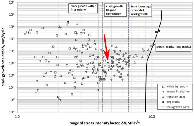
An alternative useful approach to accounting for the presence of small cracks in γ-TiAl alloys is that of Filippini et al. [17,47], where the El-Haddad model modified by Tanaka et al. [48] was applied. This combines the stress-life and damage-tolerant (FCG) approaches to fatigue by the intermediate of an inherent minimum flaw size, which has previously been related to the concept of small cracks [10]. The intrinsic fatigue stress intensity range threshold was determined from compact-tension specimens and the maximum run-out stress values were determined from plain cylindrical specimens with and without EDM-introduced artificial defects, at room temperature and 700 Kitagawa–Takahashi diagram for EBM-processed TiAl alloys. Redrawn and adapted from [47] (reproduced with permission). C. Both the Ti–48Al–2Cr–2Nb and TNB alloys were found to obey the same Tanaka law (Figure 6), despite different strengths and colony sizes. A similar percentage of lamellar colonies were produced in both alloys through electron beam melt processing. This parameter, the volume fraction of lamellar colonies, was therefore reported to dominate the HCF properties of γ-TiAl alloys.
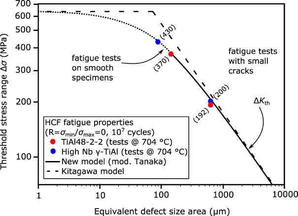
In addition to understanding the material parameters for design against fatigue failure due to flaws inherent to the production of TiAl components, it is necessary to understand the size of flaws that might be generated by object damage (foreign or domestic) during engine operation. There are relatively few published studies concerning object damage of γ-TiAl alloys. Early studies by Harding and Jones [49] employed quasi-static and low-speed drop indentations. Ballistic impact testing by Draper et al. [50,51] using a gas gun to project small steel spheres at aerofoil-shaped specimens determined the impact energy to be the dominant factor in characterising crack formation. The range of impact energies was 0.2 to 2.0 J. Where the damage exceeded the microstructural dimension (i.e. the lamellar colony size), a straightforward FCG threshold analysis of the crack length suitably predicted the measured reduction in fatigue strength [51]. Attempts to model this behaviour with a finite element model [52] identified that a lower amount of ductility occurred before crack formation in ballistic testing (1–2% plastic strain) compared with static indents (2–3% plastic strain).
More recently, Draper et al. have extended their study to third-generation γ-TiAl alloys [53]. The GMPX alloy Ti–45Al–5Nb–0.2C–0.2B displayed no improvement in the remnant fatigue strength after impact testing compared with older generation alloys such as Ti–48Al–2Cr–2Nb, hence calling into question the suitability of third-generation γ-TiAl alloys for higher strength aero-engine blade applications. Bache and Morgans [54] have undertaken simulated object damage of Ti–46Al–8Ta at much higher impact energies and using cube-shaped steel projectiles. Damage was often brittle, with surface chips ejected, and deep macroscopic cracks (>1 mm) surrounding the damage sites. Further HCF of the damaged specimens at R=0.1 with an increasing  until failure found that comparable HCF endurance strengths were achieved at 20
 C and 650
 C, although only a few samples were tested and up to a maximum of
  cycles. A plateau in fatigue strength was reached beyond an impact energy of ∼2.4 J, which suggests there exists a maximum flaw size to engineer for, however, complete specimen failure occurred upon an impact energy of 9.8 J.
Effect of temperature and environment
The effect of temperature on the fatigue threshold properties of γ-TiAl alloys has been reviewed extensively elsewhere [8,9]; however, little further progress has been made since towards understanding the effect of temperature on the micromechanisms of fatigue crack initiation and growth [28,55–60]. The effect of temperature appears to be complex. For instance, although the failure mechanism of brittle trans- and inter-lamellar fracture is unchanged from 25 to 800 C, the alloy Ti–47.7Al–1.9Nb–0.9Mn + 1 vol.-% TiB
 has a higher threshold stress intensity factor in air at 25
 C and 800
 C than it does at 600
 C [39] (Figure 7a). In a similar study [61] of FCG rates at fixed stress intensity across the same temperature range on Ti–46.5Al–3Nb–2Cr–0.2W (Figure 7b), the mechanisms involved were thought to be associated with both increased ductility upon heating, and also increased environmental embrittlement in the crack region, which nominally decreases fatigue life. Growth rates are several orders of magnitude higher in air than in a vacuum [62]. However, up to 600
 C, oxide formation is rarely reported, suggesting that oxidation-induced crack closure is not significant. An alternative mechanism for environmental embrittlement is by hydrogen uptake from water vapour. This occurs in iron aluminides [62], though the mechanism behind the temperature dependence of this is not well understood. Elsewhere, strain ageing effects in the 400–650
 C range may reduce crack tip plasticity due to increased dislocation pinning by
  , an antisite & vacancy pair, which has a negative strain-rate dependence [9].
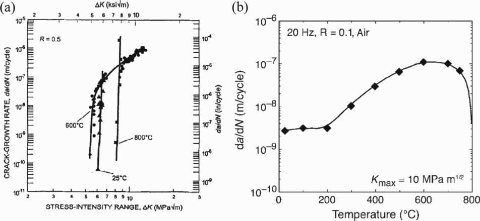
In situ SEM observations have found that cracks in γ-TiAl alloys initiate in fatigue during the latter stages of HCF life, generally within the final 10% of the lifetime [63]. However, acoustic emission measurements have found that even within the first loading cycle microcracking can initiate [64,65]. There is evidence [9,66] that the growth of fatigue cracks in γ-TiAl alloys operates by the formation of microcracks ahead of the growing crack. This can be seen as many crack initiation events that link up by more ductile-type translamellar rupture. Furthermore, the initiation of cracks has been observed in situ on electropolished surfaces, where no flaws were apparent, although laser ablation-formed micronotches elsewhere on the surface remained inactive [46]. From this evident complexity and preponderance of crack initiation in the HCF failure of γ-TiAl alloys, it is clear that understanding the mechanisms for crack nucleation is crucial to optimising the HCF properties.
The nearly flat S-N curve that is commonly reported for γ-TiAl alloys has been shown by Jha et al. [67] and elsewhere [68] to be characteristic of crack initiation both at the surfaces, and in the bulk. In itself, this distinction of flaw location is not novel. Weibull statistics have been used on brittle materials to demonstrate these two regimes [69]. The further consideration for γ-TiAl alloys is whether the mechanism of initiation is different. Although crack nucleation is common at internal inclusions and pores in ductile engineering alloys in the gigacycle regime [30], cracks in gigacycle fatigue tests of more brittle γ-TiAl alloys were also identified to be volume initiated [32]. This was in particular at γ/ interfaces and was attributed to plastic incompatibility.
At a surface, fatigue cracks may form by the extrusion of soft-mode oriented lamellae (where the angle of the lamellar interface to the loading axis, Φ, see Figure 8, lies between 15 Schematic of a cuboidal PST (single colony) lamellar TiAl specimen with the angle Φ of the lamellar planes to the vertical loading axis indicated. and 75
 ) by plasticity in the γ-TiAl phase parallel to the lamellar interfaces, known as longitudinal plasticity [70,71]. This is an initiation mechanism commonly found in ductile systems [10] and requires the local critical resolved shear stress to be exceeded. In the bulk, this mechanism may be resisted by the constraint of the surrounding colonies [72]. Nevertheless, deformation twinning in the γ-TiAl phase can generate grain boundary decohesion at a free surface in equiaxed γ and lamellar microstructures [73,74]. Ahead of static and fatigue cracks in lamellar structures, transverse twinning in the γ-TiAl phase causes lamellar interfaces to debond [66,75].
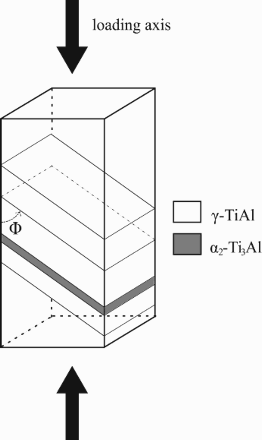
Another crack initiation mechanism in the bulk is that defined by Cottrell [76], whereby in semi-brittle crystals, the intersection of slip planes can form an obstacle to slip, and a brittle-type crack nucleates at the obstacle. This occurs when the elastic energy accumulated there by dislocation pile-up is sufficient to drive the formation of the free surfaces of a crack. This mechanism is thought to nucleate microcracks identified by TEM along the low energy  cleavage planes at the intersection between the easy operating longitudinal slip systems and the Hall–Petch strengthened transverse slip systems in lamellar γ-TiAl microstructures [77–79]. In this sense, globular, non-lamellar, γ grains in nearly lamellar TiAl microstructures may initiate microcracks as the lack of lamellar interface strengthening permits relatively unimpeded slip on multiple planes. Hence significant pile-up forces at intersection obstacles may arise. This has not been extensively investigated.
A final crack initiation mechanism in lamellar structures is decohesion of lamellae oriented perpendicular to the loading axis ( ) [65,80]. The scale of cracking achievable before any microstructural barrier is met, and the regularity of the occurrence of this initiation mechanism strongly suggests action should be taken to either strengthen the lamellar interfaces, reduce the colony size to limit the spatial extent of damage or avoid such colony orientations altogether.
Crack initiation in the latest generation high Nb alloys in both quasi-static and fatigue loading [81,82] also involves the retained ordered  -TiAl with brittle ω-Ti phase precipitates that concentrate stress. This becomes particularly problematic when the
  phase covers large amounts of lamellar colony boundaries, such that extensive microcrack nucleation in
  /ω may result in extended planes of coalescing flaws. Improved thermodynamic stabilisation of the
  phase is required to avoid this.
Microstructural dimensions appropriate to HCF characterisation
Classically, the γ grain size, or in the case of lamellar γ-TiAl alloys, the colony size, is the main microstructural dimension investigated towards optimising HCF properties. This is then supplemented by a consideration of the proportion of equiaxed γ grains versus lamellar colonies, the fatigue threshold generally increasing with decreasing equiaxed γ content [83] (Figure 9). The size of lamellar colonies influences the FCG rate as smaller colonies have a high density of colony boundaries. Hence cracks only propagate a small distance before being deflected at a boundary. However, as Dahar et al. [18] have pointed out, a large colony size maintains a cyclic crack tip plastic zone within the colony of initiation for as long as possible in the near-threshold regime. Hence, by not exceeding stage I type growth, surface roughness-induced crack closure is encouraged by the single-slip-like behaviour [84]. Therefore, although a finer microstructure limits initial crack propagation, once a short crack attains the size of several colonies, it acts as a long crack, where the presence of many weak colony boundary interfaces facilitates crack propagation [37]. It seems generally agreed that the optimum colony size is in the 50–100 µm range for several second- and third-generation γ-TiAl alloys [85,86]. In fact, according to Filippini et al. [47], the intrinsic effective threshold stress intensity range is a material property that cannot be much affected by grain size, as crack growth at the limiting rates for the application of γ-TiAl alloys is very much subgranular. Effect of the equiaxed γ content on the measured fatigue threshold. From [83] (reproduced with permission).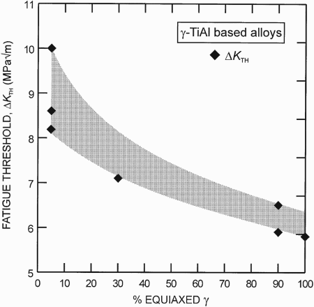
In lamellar γ-TiAl alloys, the microstructure is rarely considered in terms of the lamellar thickness with regards to HCF properties. It was generally thought that the lamellar thickness is related to lamellar colony size, being proportional to its square root [87]. Based on quasi-static toughness measurements alone, the influence of lamellar thickness is unclear: several studies [88,89] indicate that lamellar refinement increases fracture toughness, whilst another [90] found no such relationship to exist. This was possibly due to the variation of the colony size in these studies. However, a systematic study by Cao et al. [91] employing multistage cooling strategies demonstrated that the colony size and lamellar thickness can be varied independently, over several orders of magnitude. This method was adopted by Mine et al. [92] to produce polycrystalline single edge micronotched specimens with lamellar thicknesses of 0.91 µm and 3.8 µm, for a range of colony sizes. Materials with refined lamellae had lower FCG rates than those with thick lamellae. This was attributed to the high degree of microcracking in neighbouring lamellae ahead of the crack tip in the refined material. Once linked, such microcracking led to heavily roughened crack faces, and hence increased closure. In material containing thicker lamellae, there is not as much microcracking [93]. However, the wider bridging ligaments when microcracking does occur give rise to increased scatter in HCF behaviour compared with the refined lamellae condition. In contrast, Chan and Kim [88,89] found that refining the lamellae was associated with an increase in the resistance to translamellar microcracking. Plasticity upon fatigue loading generates transverse twins and slip bands that are known to be preferred propagation paths [78]. The CRSS of such transverse deformation mechanisms is dependent on lamellar thickness (Hall–Petch effect [91]) and composition; this may explain the above discrepancies. Compositional differences between the studies may have also influenced the ease of debonding lamellar interfaces. A decreasing Al content has been demonstrated to refine the lamellar thickness, as well as reducing the in-plane γ domain length, for equivalent processing conditions [94,95]. Under LCF conditions, Umakoshi et al. [70] found the strengthening of this domain length refinement to resist longitudinal plasticity, which otherwise causes the formation of surface microextrusions of lamellae that act as microcrack nucleators, as evoked in ‘Fatigue Crack Nucleation Mechanisms in γ-TiAl Alloys’ section.
Finally, long-term thermal exposure of Ti–45Al–2Mn–2Nb–0.8 vol.-%TiB at 700
 C for periods of up to 10000 h [96,97] was found to improve the maximum fatigue strength at run-out by almost 100 MPa, but only beyond 6 000 h of exposure. Appropriate variations in testpiece production methods showed that this apparent strengthening did not result from surface healing effects, but rather from stress relaxation in the bulk; the dominant microstructural change evident from imaging was simply transformation of the
  phase to γ and hence a thinning of the
  lamellae. This suggests that increasing the volume fraction of γ phase, presumably bringing this closer to the thermodynamic equilibrium, might improve the stress-life properties of lamellar γ-TiAl alloys.
Polysynthetically twinned (PST) crystals were used to study the mechanical properties of lamellar γ-TiAl alloys, mostly in Japan in the 1990s and early 2000s [70,98,99]. Samples were grown using a floating zone technique with either seeding or initial narrowing of the floating zone to produce a single α phase grain that transforms to a single stack of γ-TiAl/ Stress-life testing of PST crystals. From [70] (reproduced with permission). -Ti
-Ti Al lamellae, effectively a single lamellar colony, upon cooling. The majority of data collected concerned monotonic loading and strain-controlled LCF across the temperature range, as the study of plasticity mechanisms and the effect of the anisotropy caused by lamellar orientation to the loading axis, Φ, were the focus. An extensive review by Umakoshi et al. [70] (Figure 10) nevertheless provides some insight as to optimum lamellar orientations for HCF testing:
  performs better than
  , mainly due to the reduced strength of the
  orientation.
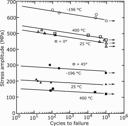
An alternative to growing bulk PST crystals is to produce micromechanical testpieces from individual lamellar colonies by selective machining. This has been achieved on TiAl alloys by micro-electrodischarge machining (µEDM) [100] and focussed ion beam milling (FIB) [100–104]. It has enabled the critical resolved shear stress of deformation mechanisms to be measured that might not otherwise be individually activated, e.g. twinning of γ-TiAl. However, studies to date have been limited to monotonic testing between 25  C [100–103] and 700
  C [104]. It is possible for in situ SEM measurements of stable crack growth to be made with micromechanical methods [105]. However, for meaningful FCG data to be achieved, the plastic zone should be considerably smaller than the testpiece dimensions, and though this is achievable for brittle ceramics [105], the plastic zone radius of γ-TiAl alloys in fatigue is several microns [106], which is at the limit for a micromechanical testpiece.
An intermediate between PST crystals (Figure 11a) and equiaxed, atextured polycrystalline microstructures is a columnar microstructure. For lamellar γ-TiAl alloys, there are two types of columnar-grained structures that can be developed that have a same Φ in all colonies [107]. The first have the lamellar planes of neighbouring colonies almost parallel to each other (Figure 11 b), the second only have equal tilt angles of the lamellar planes to the axis of the columnar growth (Figure 11 c). Multiple groups [108–111], mainly based in China, have pursued the directional solidification route on application-relevant alloy compositions to develop such columnar microstructures. Control of lamellar orientations was achieved by varying the extraction rate from a Bridgman-type furnace [108], and employing different α- or β-Ti [111] seeding techniques and multiple re-solidification [109]. Limited fatigue testing of such microstructures has been undertaken by both S-N [112] and compact-tension FCG [113] methods. For testing of Potential microstructural variety in directionally solidified crystals with the same Φ angle: (a) polysynthetically twinned crystal, PST, (b) columnar grains, approximately co-planar lamellar interfaces, (c) columnar grains, non-coplanar lamellar interfaces, but same Φ angle in every grain. In the present example,  and
and  lamellar orientations, the closure-corrected fatigue threshold was identified to be equal in both cases, at ∼5 MPa m
 , but the Paris slope was much lower in the
  case (
 vs.
vs.  for
for  ); this is consistent with increased ductility and the impossibility for growth of the primary crack along lamellar interfaces in the
  case.
case.  . Adapted from [107] (reproduced with permission).
The culmination of such directional solidification endeavours enabled Chen et al. [22,114] to produce macroscopic PST crystals of Ti–45Al–8Nb several tens of millimetres long. The lamellar orientation was determined by the extraction rate from the Bridgman furnace and not by prior seeding. The measured monotonic strength was high for the alloy system, and ductility reached 7% in the  orientation at room temperature. This method has potential for the mass production of effectively single crystal turbine blades, similarly to the single crystal nickel superalloy counterpart [114,115]. As expected, the creep strength was considerable [22]; however, data on the HCF behaviour are yet to appear.
Unfortunately, the optimum microstructure for high strength HCF properties, combined with a tolerance for FCG, is unclear. Within the context of preferentially oriented lamellar microstructures alone, there is no evidence as to whether columnar grains or PST (Figure 11) will perform better. From the absence of colony boundaries in PST crystals, their creep properties are likely to outperform their columnar-grained counterparts for the same composition and lamellar thickness. Failure by delamination at the free surfaces is known to occur from the machining of lamellar TiAl alloys [116], but is rarely investigated in the context of HCF. The varied combinations of mechanical loading – tension, torsion, bending – experienced by a component in fatigue may induce such delamination. Hence the possibility for a choice of orientations of the columnar grains could locally increase resistance to this failure mode, whereas PST crystals have no such flexibility (e.g. maintaining  , but changing the twist angle of the lamellae about the blade axis, Figure 11 c).
Studies on PST crystals have highlighted the impact of lamellar orientation on the fatigue behaviour of lamellar TiAl alloys and the potential for the production of components from an optimum orientation. However, the majority of developmental and applied alloys are polycrystalline. Throughout the 1990s and 2000s, there was a considerable drive to develop compositions and processing methods that resulted in texture-free microstructures [117], where a growing fatigue crack is therefore likely to encounter all possible colony orientations. The growth of PST crystals from arbitrary TiAl compositions to produce fatigue testpieces with a variety of lamellar orientations is a complex and onerous task. Further, it does not enable the study of changing lamellar orientations across colony boundaries on the FCG. Quite simply, PST crystals do not contain colony boundaries.
Over recent years, this has inspired efforts to establish the HCF properties of individual lamellar colonies in polycrystalline samples by the careful positioning of EDM or diamond wire pre-cracks [18,63,79,118]. The measurement of (a) Yield stress of PST specimens as a function of the angle Φ at which the compression axis is inclined to the lamellar planes, from [9], using data from Fujiwara et al. [119] (black circles) and Nomura et al. [120] (white circles). (b) Dependence of the fatigue threshold on the lamellar orientation, Φ, of the colony where the crack is propagating, from [118] (reproduced with permission). Note that both the yield stress and the fatigue threshold present a U-shaped curve against Φ, suggesting that there may be a same mechanistic cause to both. of Ti–46Al–8Nb for lamellar orientations Φ of 0–75
 at 650
 C [118] determined the most FCG resistant orientation in the near-threshold regime to be
  (Figure 12 a). The colony orientations with the lowest threshold values were those where
  , i.e. the softest orientations in PST studies [98]. The secondary orientation, Ψ, of the lamellar planes with respect to the advancing crack front, had no marked effect: lamellar planes at
  lying parallel to the crack front, or perpendicular, yielded equal
  values. Translamellar fracture was the dominant fracture mode for the majority of colony orientations, except for those close to
  , where interlamellar debonding occurred. Hence, understanding what causes the lamellae to crack transversally is paramount. The similarity between the U-shaped
  versus Φ in Figure 12(b) and that identified for the yield stress of PST crystals against Φ in compression (Figure 12a) suggests that the development of extensive longitudinal plasticity in the softest lamellar orientations causes the opening of microcracks where this intersects active transverse slip/twinning, i.e. the Cottrell mechanism detailed in ‘Fatigue Crack Nucleation Mechanisms in γ-TiAl Alloys’ section. In principle, transverse deformation mechanisms are less likely to cause microcrack formation at transverse–transverse intersections as the extent of plastic strain generated on these systems is lower [103]. This correlates well with the highest
  being at
  , where the Schmid factor is very low for longitudinal mechanisms. Furthermore, in situ SEM high temperature (750
 C) HCF loading of Ti–45Al–8Nb–0.2 W–0.2 B–0.1Y found the development of longitudinal plasticity in soft-mode oriented colonies caused colony boundary cracking at the ends of lamellae [63].
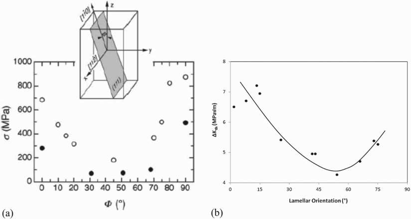
In another study [79], the fatigue cracking mechanism of lamellar colonies of Ti–45Al–2Mn–2Nb–1B as a function of both Φ and  were determined. At
  values in the sub-/near-threshold range (<10 MPa m
 ), colonies with
  failed by translamellar fracture with relatively smooth fracture surfaces; only crack deviation along transverse slip bands and twins generated roughness. If instead the local
  was higher, secondary interlamellar cracking approximately parallel to the loading axis also occurred, resulting in increased roughness of the crack surfaces, which is generally recognised as beneficial towards reducing the effective
  by crack closure [10,18]. Hence the intrinsic cohesion of lamellar interfaces may be sufficient to resist interlamellar debonding as a secondary crack mechanism in the sub-/near-threshold regime. This lack of interlamellar cracking leaves the material without the benefits of crack closure in the threshold regime of crack growth for the
  orientations. Again, the secondary orientation, Ψ, was found to have no impact on the material fatigue properties. It should however be noted that fracture surfaces following gigacycle fatigue testing indicated that higher amounts of secondary cracking were generated in the testpieces loaded in excess of
  cycles [32], and therefore at lower stresses, suggesting that a lower cycling stress applied for a more extended period can eventually generate secondary cracking.
The  orientation has generally been viewed as the weakest colony orientation [121]. In the study by Min et al. [63], the notched
  colonies failed rapidly once cracking initiated (at consistently above 93% of the total life). This was followed by a much slower crack propagation in the lower Φ colonies beyond. This steady propagation regime beyond the
  colony was identical to crack growth when cracking instead initiated in a colony with Φ closer to
  . Debonding of the lamellar planes may be so easy that interlamellar cracking in
  colonies ahead of the crack tip occurs, followed by crack expansion in the reverse direction, towards the crack tip, to sever bridging ligaments [79,113]. In contrast, Yang et al. [118] found the
  orientation to have an intermediate
  , between that of
  (best) and
  (worst) (Figure 12 b). It may be that the issue of
  colonies in [63] was overcome by the small colony size (70 µm, relative to 1 mm in [118]) such that the fatigue threshold was not exceeded after failure of a single
  colony.
Another study [18] on a textured cast billet of Ti–48Al–2Cr–2Nb instead yielded no noticeable effect of Φ on  or the Paris slope across a range of stress ratios, for loading at
  and
and  . This may have been due to the testpieces not being sufficiently textured, whereby actual colony orientations varied within ∼40
 of the nominal Φ.
Towards a microscopic model for HCF loading of TiAl alloys: A focus on plasticity
Within the field of TiAl alloy research, it is not clear what level of plasticity is optimal. Indeed, though there is a clear consensus that room temperature ductility should be raised, that is, increasing the elongation to failure, it is not clear how this influences the HCF life. This is not in the least because of conflicting interpretations of results, whereby almost identical electron images of interlamellar movement have been interpreted in different ways: microcracking [64,65,122], interlamellar sliding to form ledges [123] or longitudinal plasticity near the lamellar interface (see Figure 13). Evidently, these mechanisms also have a varying degree of impact on fatigue crack formation and growth, as has been explored in ‘Fatigue Crack Nucleation Mechanisms in γ-TiAl Alloys’ section. SEM images of similar deformation features near lamellar interfaces, interpreted as (a) ledges at lamellar interfaces [123], i.e. interfacial sliding, (b) interlamellar cracking [122], i.e. debonding of the lamellar interface, and (c) longitudinal slip in the γ-TiAl lamellae, near the lamellar interface [124]. Above (b): AFM linescan across the feature reported as interlamellar cracking; above (c): scanning transmission electron microscopy (STEM) images of a slip step near an  /γ interface. White arrows indicate the features of interest at the lamellar interfaces; black arrows are illustrative of AFM scan or cross-sectional imaging slice directions (reproduced with permission).
The study of the HCF behaviour of γ-TiAl alloys has generally focused on plasticity in the region of a crack tip, rather than in the bulk of the material [66,106]. This is possibly because in common engineering alloys, achieving HCF loading to over  cycles often means operating at stresses considerably below the yield stress, so that to exceed the local critical resolved shear stress for slip, stress concentration at a crack tip, a hard particle or a crystal boundary is required. In contrast, due to the fourfold strength anisotropy of lamellar γ-TiAl alloys (Figure 12 a), at
  the softest colonies may be loaded well above their plastic limit for longitudinal slip and twin systems. So-called microplasticity may therefore occur throughout such colonies, regardless of the existence of other stress concentrators. Evidence for this is reviewed in the next section. Hence, the HCF cycling of lamellar γ-TiAl alloys may in fact involve a variety of deformation mechanisms, that vary from colony to colony, some of which are characteristic of LCF cycling (i.e. bulk plasticity), whilst other colonies do not deform plastically.
Current common procedure is to carry out FCG testing of γ-TiAl alloys on stress relaxed, virgin material. Some data [65] has indicated that a single loading cycle below the general yield stress can have a significantly detrimental effect on the S-N behaviour of γ-TiAl alloys. In practice, a γ-TiAl component has to sustain HCF loading of an instantaneously imposed crack, as in the simulated object damage evoked in ‘Object Damage’ section, potentially towards the end of its life cycle. Despite this, no representative investigations have been made of the effect of such extended HCF loading of initially uncracked material on the FCG behaviour once a pre-crack has been introduced. This might be achieved, for example, by loading a lamellar γ-TiAl alloy for  cycles at
  , then producing an FCG testpiece and performing a conventional FCG test to identify the effect on the fatigue threshold of this pre-conditioning of the material below the general yield stress.
Since the establishment of the continuous load shedding FCG measurement strategy standard ASTM E647 for crack threshold measurement [10,11], several further loading profiles have been proposed [125,126]. A range of the envisageable strategies is illustrated in Figure 14. ASTM E647 corresponds to case (b); others in [125,126] are (g, i, j) and one of the non-standard ones (d) has been applied to a γ-TiAl alloy in [127]. In selecting a strategy for FCG testing of γ-TiAl, some of the considerations are as follows. First, a constant A selection of possible loading strategies for measuring the FCG rate  (right-hand column) facilitates separation of the p and q exponents in Equation 2, where for intermetallics
  . Depending on whether load is increased (c, g, k) or shed (a, e, i), the fatigue threshold is defined by the no-growth–growth transition, in either the forward or the reverse direction, respectively. This transition is defined in ASTM E647 to be at a growth rate of
  m cycle−1. Importantly, though, the size of the plastic zone ahead of the crack tip varies, being larger in decreasing
  loading than in increasing
  loading. In the loading strategies where a short loading period at a large stress intensity range,
  , precedes FCG testing, the fatigue crack must now grow in a very large plastic zone.
  as a function of
  , and hence determining the fatigue threshold where
  m cycle−1 (growth/no-growth transition). The FCG specimen is loaded at
  for an extended period (as per ASTM E647 [11]), followed by successive steps
  ,
,  and so on, until an FCG rate of
  m cycle−1 is either subceeded or exceeded, depending on whether
  is being decreased (a, b) or increased (c, d), respectively. Constant
  and constant
  versions of each exist. Further, prior cycling at a large stress intensity range
  for a short period (e–h) may serve to generate a large plastic zone ahead of the crack tip within which the near-threshold crack must then grow. Finally, the large
  cycling may be applied between each step in
  ,
,  ,
,  (i–l) to remove history effects of the previous loading step by forcing the near-threshold crack to grow in the same sized large plastic zone at each step. Extended from [125] (reproduced with permission).
There is no consensus as to which test strategies are most damaging or conservative, as this may be material dependent. It is reported in other engineering alloys [126] that prior cycling, even below the no-growth limit, can significantly reduce the fatigue life: load history can change the ranking of materials by FCG threshold. In a Ti alloy, for example, the strategy (i) produced a lower value for the fatigue threshold than (g) [125], although (g) was thought to be more representative of conditions during practical use. Lerch et al. [128] have investigated the behaviour of a γ-TiAl alloy Ti–46.5Al–2Cr–2Nb upon step increases in the applied cyclic stress during tests aimed at determining the maximum run-out stress. No evidence of coaxing was found, that is to say that there is apparently no load history in this alloy resulting from strengthening by strain ageing at lower stress levels. This does not, however, preclude overstress cycles (even a single cycle) from having a significant impact on the fatigue life.
For γ-TiAl alloys, although the shape of the crack tip plastic zone is known to be inconsistent with the predictions of continuum mechanics [106], the plastic zone size in application conditions is likely to be considerably different to that in a simple HCF test due to the additional underlying LCF or steady-state loading to the component. This LCF can lead to both strengthening by work hardening, or microcracking [66], in the crack process zone. The above FCG testing strategies (i–l) are able to reproduce the salient features of the superimposed LCF and HCF loadings, and may hence determine realistic or more conservative values for  . A more systematic approach, by comparison of the effect of the different loading strategies in Figure 14 on the measured fatigue thresholds, and an understanding of the underlying mechanistic reasons for this, may be necessary to gain confidence in the HCF lifing of γ-TiAl alloys.
Furthermore, there has been little work on the variable amplitude fatigue properties of γ-TiAl alloys [23]. This is possibly surprising as HCF in the proposed applications results from the relaxation of vibrations [5], where the amplitude varies. In general, however, variable amplitude fatigue is a loading regime for which the theory is also not well understood [126].
Most of the studies on the fatigue of titanium aluminides where an effort has been made to seek a microstructural understanding of the deformation structures and mechanisms have used either scanning electron microscopy (SEM) to image flaw formation in situ [60,63] or transmission electron microscopy (TEM) to image dislocation and twin structures in samples extracted after testing. However, an image of the dislocation structure at one instance does not allow the plastic strain accumulated thus far in that region to be determined. Even techniques such as high-resolution electron backscatter diffraction (HR-EBSD) [129] do not capture this as they measure only the elastic strain and rotation of the lattice, rather than the permanent, plastic strain associated with dislocation motion.
Work by Beran et al. [130] has enabled post-mortem TEM observations to be confirmed by in situ neutron diffraction during the cyclic loading of the testpiece. The volume fraction of deformation twins in the γ-TiAl phase was hence measured by both techniques; it rarely exceeded 0.025. Twinning as a plasticity mechanism in fatigue was found to be rapidly exhausted.
The past two decades has seen substantial progress in the field of digital image correlation (DIC) strain mapping [131], whereby the strain tensor for deformation in the surface plane is obtained by matching the positions of fiducial surface features before and after deformation. The strain developed between individual areas only  [132] in size can be measured by imaging in an SEM. Similarly to HR-EBSD, this technique is non-destructive and hence may be applied throughout the fatigue cycling of a testpiece. The first application of DIC strain mapping to TiAl alloys was made by Jiang et al. [133] on Ti–44Al–8Nb–1B loaded monotonically at room temperature in tension to just below and above the yield stress to characterise microplasticity. Elsewhere, Niendorf et al. [134] cyclically loaded Ti–45Al–5Nb–0.2B–0.2C (TNB-V5) at 25
 C and 700
 C to successively higher loads until failure, with regular pauses at maximum load to image the surface for DIC strain mapping. Niendorf et al. demonstrated that the origin of final fracture within the gauge length upon LCF loading could be determined by DIC strain mapping after only 20% of the total fatigue life. Jiang et al. were able to show that in lamellar and nearly lamellar microstructures, plasticity first occurs at only ∼75% of the 0.2% proof stress, although in duplex microstructures this early onset was not seen; this was supported by post-mortem TEM imaging. However, both studies suffered from insufficient resolution in the strain maps to determine the exact location and distribution of plasticity relative to the lamellar microstructures. This was mainly due to their use of optical microscopy for image acquisition and insufficiently refined surface speckle patterns for higher resolution mapping.
More recent and extensive use of the DIC technique on TiAl alloys has been made by Filippini and co-workers [47,135–137]. They have measured the accumulation of plastic strain during monotonic and LCF loading of Ti–48Al–2Cr–2Nb testpieces with a duplex microstructure. Despite optical microscopy also being employed for pattern imaging, sufficient resolution was achieved to measure some local variations in the distribution of plastic strain between successive High-resolution digital image correlation strain map for a lamellar grain captured from a sample cyclically loaded (ex situ) in compression at a maximum nominal stress of 390 MPa and R=0.05. Axial (vertical here) strain accumulates inside the defined lamellar platelets which are composed by the γ-TiAl phase. From [136] (reproduced with permission). -Ti
-Ti Al and γ-TiAl lamellae, and the effect of lamellar orientation to the loading axis. Strain accumulation was identified in the vicinity of
  /γ lamellar interfaces in soft-mode oriented lamellar colonies (see Figure 15). This was consistent with DIC results obtained by Bode et al. [43] on an alloy of composition Ti–46.5Al–2.5V–1Cr. In both cases, lamellar orientations to the loading axis were obtained from the measurement of surface traces. However, soft-mode colonies might present a surface trace perpendicular to the loading axis and thereby appear to be hard-mode colonies, and vice versa. Attempts were made to assess the error in this by resolving strains along lamellae to calculate a minimum bound of confidence for the local plastic shear strain [135].
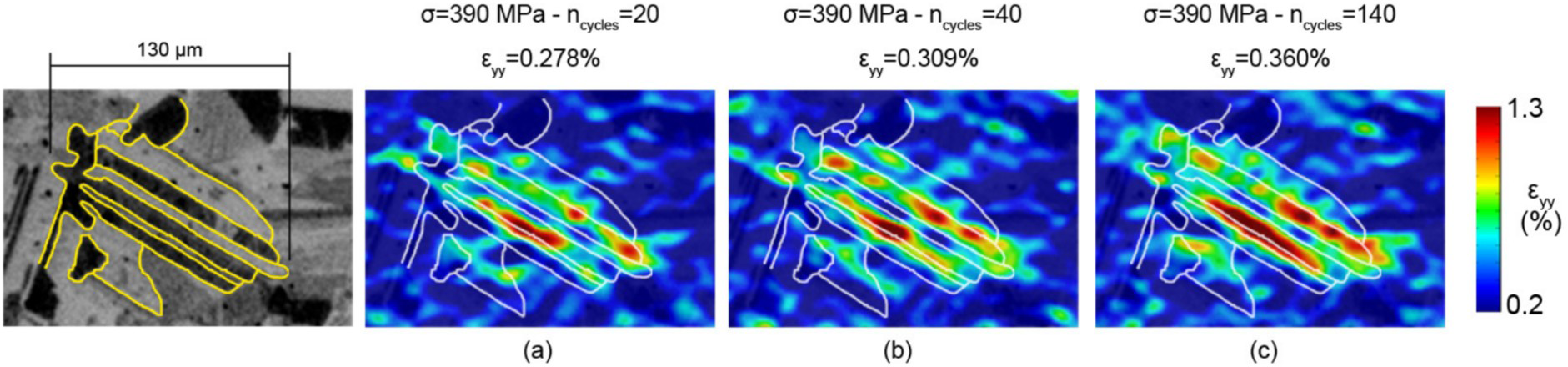
All DIC studies thus far on γ-TiAl alloys have used etching or sand blasting to produce the speckle pattern. To date, no systematic assessment exists of the effects of etching on the surface strains measured by DIC. However, these patterning methods may have preferentially weakened the lamellar interfaces and the colony boundaries and thereby caused strain to accumulate in these regions more so than on a flat, polished surface.
In short, digital image correlation strain mapping can measure the accumulation of local plasticity and damage during cyclic loading of γ-TiAl alloys. If applied using a high temperature stable nano-scale overlay speckle pattern [138,139], combined with SEM imaging [140,141], it has the opportunity to map plastic flow to the scale of individual γ lamellar domains, at aero-engine operational temperatures, without artificially weakening microstructural features. This would enable the location of slip/twin deformation during HCF, as well as crack initiation, to be studied as already achieved in other metallurgical systems [142].
The present review has not focused on alloy compositions. One may note, as in [5], that conventional Ti alloy development has seen many incremental improvements in composition, and hence successive material replacements, without much change to processing. In contrast, for γ-TiAl alloys, most of the currently preferred and applied chemistries were developed over 20 years ago, e.g. Ti–48Al–2Cr–2Nb. The development of alloy compositions targeted at improving the strength and reliability of TiAl alloys under HCF loading at operational temperatures is being hindered by a lack of clarity as to optimal microstructures. Recognising that microstructural parameters and strengthening mechanisms beneficial to single colony (PST) components are not necessarily optimal for polycrystalline structures, and vice versa, might facilitate more directed compositional development.
An example of how the composition might be tailored for improved HCF properties is to consider secondary cracking by interlamellar debonding, which is a potential toughening mechanism that might be exploited in colonies where translamellar cracking prevails, e.g. in Atom probe tomography reconstruction of the  PST and columnar-grained components. It was mentioned in ‘Fatigue Cracking of Specific Colony Orientations in Polycrystals’ section that this mechanism does not operate in Ti–45Al–2Mn–2Nb–1B at stress intensity factors close to the threshold value, yet it is in this regime that TiAl alloys are to be operated. Furthermore, in untextured polycrystalline alloys, interlamellar debonding in
  colonies can lead to crack initiation; absorption of mechanical energy by interlamellar debonding is therefore undesirable in such microstructures. Measurements of the lamellar cohesion energy, its dependence on Al content and other alloying elements, and an understanding of the mechanisms therefore are scarce. Difficulty arises because accurate compositional measurements with lamellar scale resolution, e.g. by STEM-EDX [143], are difficult given the light elements present (Al, C, B) [144]. On the other hand, atom probe tomography (APT) studies of lamellar TiAl [145–148] have the potential to quantify the partitioning of elements to interfaces [149]. The accumulation of C in Ti–43Al–4Nb–1Mo–0.1 B–0.75C (TNM) at a
  /γ interface was recently measured [147,150] (Figure 16). The lamellar cohesion strength also depends on the composition of the matrix, which defines the local stresses associated with semi-coherency at the interface. Direct microscale measurement of the interfacial strength is possible [151], however, current methods can generate spurious results, stemming from the sample preparation process [152]. Density functional theory modelling of interfacial energies for differing γ/γ interface types exists [153], however, a more systematic analysis of the effect of a range of alloying elements on the interlamellar misfit stresses is lacking. In short, if γ-TiAl alloy compositions are to be tailored for HCF performance, an improved understanding of how solutes influence the interlamellar cohesion strength would be beneficial, and is achievable with current methods.
  /γ interface in Ti–43Al–4Nb–1Mo–0.1B–0.75C. Note the peak in C, arrowed in red, near the interface; variations in the C content at the interface may change the cohesion strength of the
  /γ interface. Adapted from [147] (reproduced with permission).
Summary of the microstructural properties to optimise for improved HCF behaviour of fully or nearly lamellar γ-TiAl alloys as a function of lamellar orientation, Φ.
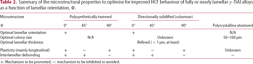


+: Mechanism to be promoted; −: mechanism to be inhibited or avoided.
Footnotes
References
 ) TiAl alloy
 C
C ) titanium aluminides
 C in nickel based superalloys